ISSN Online: 2327-5227 ISSN Print: 2327-5219
Auto Opening Door and Car Identification
Sanner H. Mahmood, Oulla G. Hassan, Ayad M. Kwad, Safa F. Abass
Department of Networks Engineering, Al-Iraqia University, Baghdad, Iraq
Abstract
Design an Automatic Door System using a unique wireless ID by using infrared ray or Bluetooth technology. That consists of a sensing unit, control unit and drive unit to open and close doors at the entrance of a car that has the unique ID. This process is controlled by using Arduino Leonard programmed with IDE free open source software, that receives the signal code from the car which sends the ID through IR LED or Bluetooth by using a mobile application, decode it. And switch ON the driver that controls the DC motor. This system was designed considering some factors such as low cost and low power requirements, availability of components and low distance so there is no interference. The hardware design and software development are de-scribed, and all of the tests indicate that all component goes according to the initial design of this research.
Keywords
Automatic, Auto Opening, Car, Door, Identification, Security
1. Introduction
Usage of new generation technologies is becoming an important requirement in these days. These technologies can be used in the security of building or home to reduce hu-man efforts, personal safety and protect building structure.
Many researchers have proposed various methods of security systems [1] [2]. Each of these systems has its own advantages and disadvantages [3]. One of the important secu-rity systems in building is door access control. Most doors are controlled manually, es-pecially by security personal that employed by the organization, through the use of handles and locks with key to operate the locks. Examples are banks, hotels, motels and so on; some are controlled by switches while others are controlled by the biometric techniques. These techniques are to enable automatic verification of identification by computer assessment of one or more behavioral and/or physiological characteristics of How to cite this paper: Mahmood, S.H.,
Hassan, O.G., Abass, S.F. and Kwad, A.M. (2016) Auto Opening Door and Car Identi-fication. Journal of Computer and Commu-nications, 4, 132-141.
http://dx.doi.org/10.4236/jcc.2016.415013
a person. Recently, biometric methods used for personal authentication utilize such features as face recognition, voice recognition, hand shape, finger print, and iris pat-terns of an individual [4] [5] [6].
Current access control systems for automatic door control require a sensor able to detect a moving object or a pedestrian crossing the gate. This approach does not take into account the trajectory of pedestrians, and therefore cannot estimate movements. As an example, if a pedestrian crosses the area in front of the door but does not want to cross the gate, the control access board detects his/her presence and anyway opens the door. In this case, the system is not efficient, since it leads to a waste of energy in terms of electricity, air conditioning, or heating and decrease the system lifetime with unne-cessary open/close actions.
The door access control is a physical security that ensures the security of a building or home by means limiting access to building or home to specific car. These system control on the opening/closing of the door by receiving a decoded signal from a car, process it by a microcontroller if the code was authorized by the microcontroller then the door open. Waiting until the car entre and then close it.
The main remote control technology used in the home is infrared. The signal be-tween IR LED and PIR (Passive Infra-Red) is infrared pulses, which are invisible to the human eye. The sender sends out a pulse of infrared light when a car closed from a spe-cific door. The infrared light pulses represent a binary code that corresponds to a cer-tain command, such as (power on). The receiver passes the code to a microcontroller, which decodes it and carries out the command.
Using Bluetooth Wireless Technology (BWT) is not just for transfer of data and files only. In recent years, automation is one of the applications of Bluetooth technology. BWT enabled devices operate in 2.4-gigahertz (GHz), that use a technique called fre-quency hopping to minimize eavesdropping and interference from other networks. With frequency hopping, the data is divided into small pieces called packets. The transmitter and receiver exchange a data packet at one frequency, and then they hop to another frequency to exchange another packet. They repeat this process until all the data is transmitted.BWT devices randomly hop between frequencies up to 1600 times per second. This gives BWT networks a high immunity to interference from other 2.4-GHz devices [7].
With these qualifications of IR and Bluetooth; we offer a door automation system and car identification based on IR and Bluetooth.
2. Methodology
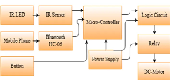
2.1. System OverviewFigure 1. The block diagram of an automatic door.
Receiver, Bluetooth device or directly pressing the close button on the board. If no one of previous action is executed, the door is closed automatically after 40 seconds. Neither of the above closing methods can turn off the light. The light is also turned on by mak-ing any motion in the garage by PIR sensor. The light will turn off automatically after 60 second from any last order.
2.2. Electronic Lock System
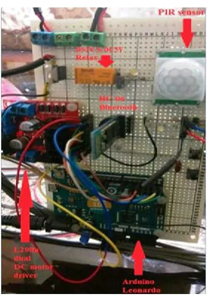
The design of an electronic lock system used for opening and closing of the gate system is shown in Figure 2. The electronic lock system comprises of power supply unit, sens-ing unit, control unit and door unit (it contains relay and driver circuit). The electronic lock our system shown in Figure 3 and Figure 4.
1. Power Supply Unit
The microcontroller board and the driver board for the motors are supplied with 12 DC volts. The sensing unit is supplied by 5 DC volts through the microcontroller board. The relay is supplied by a 5 regulator volt directly from the main power supply. 2. Sensing Unit
The sensing unit consists of Bluetooth HC-06, IR receiver, PIR “Pyroelectric infra-red” and IR obstacle avoidance.
a) Bluetooth HC-06 Sensor
The HC-06 module shown in Figure 4. An application on the mobile phone is used to control this sensor by searching Bluetooth name “HC 06”, then connecting with by entering the password “1234”. When pressing on “ON” the Bluetooth sends characters’ bytes in the form of “1” for opening the door, and when pressing on “OFF” sends cha-racters’ bytes in the form of ‘0’ for closing the door.
b) IR receiver “KSM-603LM2M-2” Sensor
The IR Receiver receives two unsigned 32 bit long integer from the remote control, one of them is used for opening the door and the other for closing it.
c) PIR “Pyroelectric infrared” Sensor
Figure 2. The Block diagram of an electronic lock.
Figure 3. IR sender and IR avoidance.
in the garage. When this sensor detects any movement in the garage it will automati-cally open the light, and then turn off after 60 second from any last order. Also when an obstacle is situated in front of the door it turns on the lights.
d) IR obstacle avoidance Sensor
This sensor is mounted at the border of the left side of the front door shown in Fig-ure 4, used to prevent closing the door while the car in the middle of the door entrance. 3. Control Unit
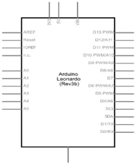
It is using Arduino Leonardo as the main processing unit shown in Figure 4, and the schematic of the controller shown in Figure 5 below. Used to control the opening and closing of the sliding door.
The microcontroller is programmed using the Integrated Development Environment (IDE). The control unit gets the input from the sensing unit, decodes them and then takes the following steps:
• Control the gate opening and closing. • Generate the timing signal for the system. • Decode signal that sensed by sensing unit. • Activate the buzzer and light.
[image:5.595.258.489.407.685.2]Opening the door by whatever the way; resets a timer system within the Arduino board, and this timer increases with each 500 milliseconds until its counter reaches 40 s where a signal is passed to close the door if not closed manually .Once the counter reaches 60s another order passes to turn off the lights. When closing the door manually,
it only takes 20s second to turn off the lights. There is no way to turn off the lights ma-nually. By pressing any one of the two buttons can interrupt any function in the board and do specific function which is either opening or closing the doors.
Through all the steps of the control system, a buzzer signal is used for debugging and for notification, at different length, the buzzer can tell you whether the doors are open, closed, you gave a wrong order, or the doors are closed and waiting for the lights to turn off. There is no buzzer signal when an obstacle is situated between the doors or when the time after the last signal is passed 60 seconds.
4. Door Unit
a) DS2Y-S-DC5V Relay
When PIR shown in Figure 4, detect a motion, it sends a signal to the transistor, transistor sends a signal to the relay, it activates the electromagnet, generating a mag-netic field that attracts a contact and activate the lights. When the power is switched off, a spring pulls the contact back up to its original position, switching the lights off again.
b) L298n dual DC motor driver
When signal come from Arduino to open the door ,the current will flow in the motor from one pole to another, but when the signal come from Arduino instruct the door to close again, L298n dual DC motor driver will change the flow of current in opposite di-rection. The L298n dual DC motor driver is shown in Figure 4.
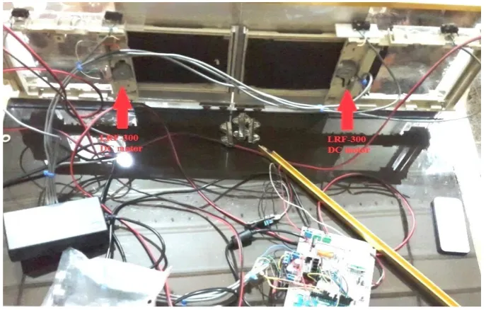
c) LRF-300 DC motor:
[image:6.595.202.546.466.685.2]It has Low noise level, Long life time, Small fire, Smooth operation, Easy and conve-nient for installation. Used to open the door when receive a signal from IR sender or Bluetooth, and also for close it by operating in the reverse direction.LRF-300 DC mo-tors located on the each side of the door, each one of them opens the door, that belong to separately from each other, as it shown in Figure 6 below.
2.3. Software Lock System
The Arduino is the main processing unit that executes the program developed by IDE. When a car that has ID come in the front of the door that open either by IR sender or Bluetooth, if IR receiver used, then IR LED in a car send a (car ID) signal to IR receiver, the Arduino processed the ID if it is authorized the door open. If an application in mo-bile phone used to open the door, Arduino also processed the incoming ID from Blu-etooth if it is authorized the door open.
In the two way of opening the door, a timer count to 40s and close the door , but if the car was in middle of the two doors, then the door do not close until the car moved away from the middle. Also buzzer and light turn on into 60 s.
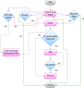
If the emergency case happen and the user want to enter/exit immediately, the user pressed on the open/close button an interrupt happen and the door open/close. The flowchart in Figure 7 below describes how the software lock.
3. Results and Discussion
[image:7.595.205.542.334.687.2]The door successfully opens automatically when the correct car ID was captured from
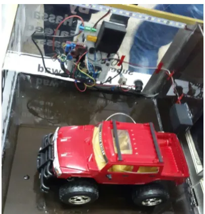
IR LED or Bluetooth, also closed automatically after 40 s or by Bluetooth device or pressing the close button. The prototype of this project is shown in Figure 8 below.
Figure 9 shown below describes Bluetooth error percentage that we obtained from trying to open the door several times to see the response. This error obtain when we out of the coverage distance, or when other wireless equipment operate on the 2.4 GHz frequency may that cause interference.
The Bluetooth HC-06 module can response to the signal up to 10m with any angle direction that mean there is no limitation in using Bluetooth in whatever direction.
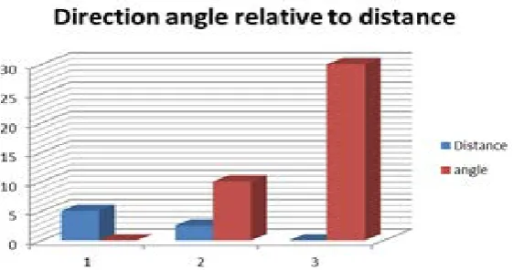
But with the IR receiver there is limitation in the direction of the car. The best re-sponse was found when the car was in the front of the door. Figure 10 shows the rela-tionship between distance and angle direction.
[image:8.595.272.475.291.503.2]Figure 11 explains that IR does not response in a distance more than 5 m, in 5m the only response we have in a point to point position with IR. The closer distance to IR, more angle direction.
[image:8.595.250.496.535.689.2]Figure 8. The prototype of project.
Figure 10. Relationship between distance and angle direction.
Figure 11. Relationship between distance and angle direction.
This limitation in distance has an important security implication: in the event of a pursuit by criminals the owner’s car can open the door while still moving towards it and then close the gate immediately after gaining entry from a close button.
4. Conclusion
The system described in this project has been constructed to operate a small door de-pend on car identification. The systems successfully operate by using infrared ray and Bluetooth wireless technology. Arduino Leonardo was the main control unit that con-trolled on the opening/closing door depends on the received signal from sensing unit. The prototype constructed in order to demonstrate the workability of the design. It can be modified to form part of an electronic toll collection and other entry or pass through systems that require much car identifications. A bigger door can still be operated with the control system described but the driver circuitry must use components that can handle more power required to drive the door.
References
[image:9.595.236.517.258.406.2][2] Duhame, D.C. (1982) Home Security and Garage Door Operator System. ed: Google Pa-tents.
[3] Petersen, T., Williams, P. and Mills, A. (2001) Analysis of the Value of Home Automation Systems. Facilities, 19, 522-532. https://doi.org/10.1108/02632770110409503
[4] Kung, S.Y., Mak, M.W. and Lin, S.H. (2004) Biometric Authentication: Machine Learning Approach. Prentice Hall, Englewood, NJ.
[5] Osadciw, L., Varshney, P. and Veeramachaneni, K. (2002) Improving Personal Identifica-tion Accuracy Using Multi Sensor Fusion for Building Access Control ApplicaIdentifica-tion. In:
Proceedings the Fifth International Conference for Information Fusion, 1176-1183.
[6] ADSL (2009) All Data Sheet Library. http://www.alldatasheet.com [7] Bluetooth Wireless Technology Basics.
Submit or recommend next manuscript to SCIRP and we will provide best service for you:
Accepting pre-submission inquiries through Email, Facebook, LinkedIn, Twitter, etc. A wide selection of journals (inclusive of 9 subjects, more than 200 journals)
Providing 24-hour high-quality service User-friendly online submission system Fair and swift peer-review system
Efficient typesetting and proofreading procedure
Display of the result of downloads and visits, as well as the number of cited articles Maximum dissemination of your research work