International Journal of Emerging Technology and Advanced Engineering
Website: www.ijetae.com (ISSN 2250-2459, ISO 9001:2008 Certified Journal, Volume 6, Issue 12, December 2016)
263
Optimization of Isolating Materials Used for Forced Vibrations in
Grinding Machine Structure from FEA and Experimental Aspects
Rajashri T. Patil
l, R. B. Barjibhe
2, A.V. Patil
31
Research Scholar, Department of Mechanical Engineering, SSGB, COET, Bhusawal, Jalgaon (MS).
2PG Coordinator, Department of Mechanical Engineering, SSGB, COET, Bhusawal, Jalgaon (MS).
3
Head, Department of Mechanical Engineering, SSGB, COET, Bhusawal, Jalgaon (MS).
Abstract: The point of this Project is to the utilization of ANSYS programming and FFT (Fast Fourier Transform) Analyser to decide the natural frequency of vibration modes and locate the free recurrence of the grinder Mounted on manufactured welded structure. The impact of vibrations transmitted to the structure is debilitating the welded joints furthermore affecting on precision of the segment because of vibration. Platform grinder running at consistent speed, by discovering regular recurrence of the Pedestal grinder part to counteract reverberation created or vibration produced by body which cause the disappointment Welded structure underneath it, the trial has made to enhance the life of that structure by giving halfway isolation material like Rubber, plywood and thick cotton sheet, and discover that the most reasonable moderate material use for the vibration confinement.
Keywords: ANSYS, FFT, isolation material, natural frequency, structure, vibration, etc.
I.
INTRODUCTION
A] VIBRATION
Any motion which repeats itself after a certain interval of time is called vibration. The swing of pendulum is a typical example of vibration. The theory of vibration deals with study of oscillatory motions of bodies and the forces associated with them. A vibration can caused due to external unbalanced force also. A vibratory system, in general, includes elastic member for storing potential energy, a mass or inertia member for storing kinetic energy and damper by which gradual loss of energy takes place. A simple pendulum as shown in Figure 1 is an example of vibration system. Spring for elastic nature,
mass acts as a means for kinetic energy.
Like pendulum, vehicle suspension system, simply supported and cantilever beam, lateral vibrating string, vibration due to unbalance reciprocating or rotating force, etc. are examples of vibrating system.
Figure 1 Free Vibrations of Spring Mass System
B] PROBLEM DEFINITION
Taking simple application of machining like grinding. In grinding, the small part of cutting tools are finished to obtain desired cutting edge. Today‟s grinders are built up on a fabricated welded structure for sake of convenience. Such grinders have speed range from 2000 RPM to 10000 RPM. Due to this high speed, the dynamic motion of the grinder is directly transmitted to the structure and structure vibrates with certain frequency. If this frequency of excitation of structure coincides with natural frequency of grinding structure the structure vibrates with maximum amplitude results in resonance phenomenon. This resonance may cause damage to the grinding structure.
International Journal of Emerging Technology and Advanced Engineering
Website: www.ijetae.com (ISSN 2250-2459, ISO 9001:2008 Certified Journal, Volume 6, Issue 12, December 2016)
264
In passive type isolation the rubber pads and cotton type materials are used to avoid transmission of excessive vibrations to structure. These elements provides certain type of damping to vibrations. "Passive vibration isolation" refers to vibration isolation or mitigation of vibrations by passive techniques such as rubber pads or mechanical springs,
The present study includes the study of vibration isolation with combined isolating material. The model has created with theoretical data and evaluated by standard vibration analysis method. To validate the result, software modelling has performed in CATIA V5R19 and analyze in ANSYS 15.0 to obtain results. The FFT analysis also performed to validate the result and measuring the actual frequency of vibration of grinding structure.
C] PROPOSED METHOD
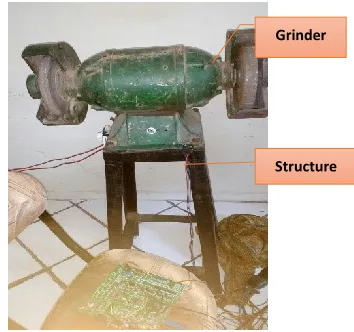
Pedestal grinder or bench grinder (Figure 2) is a type of bench top grinding machine used to drive abrasive wheels. A pedestal grinder is a larger version of a bench grinder that is mounted on a pedestal, which is bolted to the structure on floor. These types of grinders are commonly used to hand grind cutting tools and perform other rough grinding.
Depending on the grade of the grinding wheel it may be used for sharpening cutting tools such as lathe tools or drill bits. Alternatively it may be used to roughly shape metal prior to welding or fitting. A wire brush wheel or buffing wheels can be interchanged with the grinding wheels in order to clean or polish work-pieces.
Grinding wheels designed for steel should not be used for grinding softer metals, like aluminum. The soft metal gets lodged in the pores of the wheel and expands with the heat of grinding. This can dislodge pieces of the grinding wheel.
A mathematical model is base for studying the various properties of vibration. So, mathematical model has created by using various stiffness and damping properties. Solving the mathematical model for grinder to calculate the natural frequency and force transmitted.
FFT analysis has performed for the validation of results obtained by theoretical data. Here FFT Analyser is used to find natural frequency of structure.
Geometric modeling shows the better results for analyzing the objects. Therefore, a solid model has created in CATIA V5R19 by using certain geometric modeling commands. The solid model is then imported in ANSYS Workbench to observe the vibrations of structure. Then modal ansys has carried out to find the natural frequency of the model. The boundary conditions are given as fixed at base and free at the connection between grinder and structure.
The typical model of grinder with structure is shown in figure 2. For our experiment we use the grinder as per following details.
Power: 0.55 Watt or 0.75 hp, Speed: 3000 RPM,
Made: Mahalakshmi pvt. Ltd., Shaft Dia.: 20 mm,
Wt.: 35 Kg,
Mount: Mounted of Fabricated Welded Structure.
Figure 2 Grinder Assembled on Structure
II. MATHEMATICAL MODELING
Here the mathematical equations related to vibrations are used to find out natural frequency and its first three modes.
These are
√ ⁄ ………..…………. (Equation 1)
………..…. (Equation 2) ……..…. (Equation 3) Frequency ratio, …………... (Equation 4)
……… ……….. (Equation 5)
√( ) ( ) ……….… (Equation 6)
Or, we can write,
√( ) ( ) ..…………....…. (Equation 7)
And phase difference is given by,
(
) ..………... (Equation 8) Grinder
[image:2.612.381.558.262.428.2]International Journal of Emerging Technology and Advanced Engineering
Website: www.ijetae.com (ISSN 2250-2459, ISO 9001:2008 Certified Journal, Volume 6, Issue 12, December 2016)
265
[image:3.612.63.264.232.366.2]A Natural Frequency is the key point for obtaining and comparing the results from FEA and FFT. So here, natural frequency and its three mode shapes are considered for the analysis of the system. The natural frequency is calculated by conventional technique. The properties are taken from table 1. The three modes of vibration is calculated and shown in table 2.
Table 1 Properties of Materials Sr.
No. Material
Young Modulus
[GPa]
Stiffness 106 [N/M]
Damping Factor
1 Structural
Steel 200 250 0.00
2 Rubber
Pad 0.05 102 0.15
3 Plywood
Pad 11 15400 0.07
4 Cotton
[image:3.612.370.532.367.495.2]Pad 3 720 0.05
Table 2 Numerical Results of Natural Frequency
Material
Numerical
First Mode
[Hz]
Second Mode
[Hz]
Third Mode [Hz]
Stand 404 595 825
Rubber Pad 218 320 444
Plywood 400 590 818
Cotton Pad 348 513 710
III.
FINITE ELEMENT ANALYSIS
Finite element analysis has been carried out by ANSYS 15 software. ANSYS is a general-purpose finite-element modeling package for numerically solving a wide variety of mechanical problems. These problems include static/dynamic, structural analysis (both linear and nonlinear), heat transfer, and fluid problems, as well as acoustic and electromagnetic problems.
Here the structure is discretized into approximately 3145 elements having 8633 nodes by default meshing of tetrahedral and mesh size is 2 mm. The solution is obtained by using ANSYS Work Bench modeler. The 20 modes of natural frequencies are found out and from the resulted data, the comparison has made among the all types of insulating materials. The results are tabulated in Table 2.
For the ANSYS results first material is selected and material properties are defined. The model created by CATIA has been imported in ANSYS workbench. Then meshing is done by default mesh size. The model is described by around 3145 elements connected by 8633 nodes. The boundary conditions are specified as free at bottom and rotational velocity at the top of structure. Obtain the solution at least 20 modes of vibration. Compare the results with numerical.
The ANSYS 15 finite element program was used for modal analysis of structure. For this purpose, the total 4 models are created depending on isolating materials in CAD software (CATIA) and imported in ANSYS (.iges file). Each model have fixed at bottom and rotational velocity at top surface.
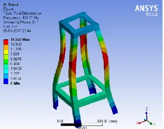
The figure 3-6 represents the modal analysis for calculation of all types of structure. The table 3 shows the tabulated data of finite element formulation for all types of models.
[image:3.612.61.264.400.526.2]Figure 3 Results of FEA for Structure without isolating material
International Journal of Emerging Technology and Advanced Engineering
Website: www.ijetae.com (ISSN 2250-2459, ISO 9001:2008 Certified Journal, Volume 6, Issue 12, December 2016)
[image:4.612.78.245.148.281.2]266
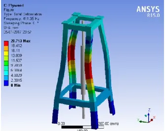
[image:4.612.72.253.313.457.2]Figure 5 Results of FEA for Structure with Plywood as isolating material
[image:4.612.69.257.494.649.2]Figure 6 Results of FEA for Structure with Cotton as isolating material
Table 2 FEA Results of Natural Frequency
Material
ANSYS
First Mode [Hz]
Second Mode
[Hz]
Third Mode [Hz]
Stand 431 608 768
Rubber Pad 168 343 411
Plywood 412 585 790
Cotton Pad 343 485 705
IV.
FFT ANALYSIS
To perform the experimental work on structure, certain steps have to be followed. The following steps are used for experimentation on structure. Firstly, the structure is mounted on base.
The grinder is fitted on structure by using bolts. Initially no isolating material added in between structure and grinder. An acceleration sensor is attached at one side of the bolts. The laptop with LabView software installed has been attached to sensor. Making grinder in running position, the reading are taken by LabView software in laptop as shown in figure 7. The Structure dimensions for experimentation are
Structure length: 740 mm.
Cross-section Member: 4 mm × 1 mm Flange and 3 mm × 1 mm Web
Grinder Position: on the Top of structure
Sensor Position: Towards the one of the Bolt mounted between structure and grinder.
Following steps are adopted for experimentation work.
1. Mound the grinder on structure by using bolts. 2. Attach sensor towards one of the bolt mounted.
3. Make necessary connections like power supply and connection to laptop.
4. Start LabView software from laptop, make new file. 5. Start the grinder, due to vibrations new spectrum generated in this file.
6. Observe the frequency plot as time domain and amplitude vs time.
7. Save the file by giving suitable name.
8. Stop the grinder and mount the rubber pads between grinder and structure with the help of bolts.
9. Repeat the procedure 2-8 for reading.
10. Similar way, take reading for Plywood and Cotton pads. 11. Obtain the data in terms of images from software module.
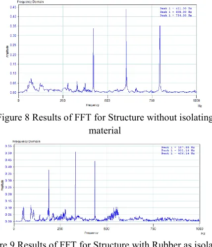
[image:4.612.371.529.570.687.2]The results of FFT are shown in figures 8-11. The table 3 shows the results of FFT in tabulated form.
International Journal of Emerging Technology and Advanced Engineering
Website: www.ijetae.com (ISSN 2250-2459, ISO 9001:2008 Certified Journal, Volume 6, Issue 12, December 2016)
267
Figure 8 Results of FFT for Structure without isolating material
Figure 9 Results of FFT for Structure with Rubber as isolating material
Figure 10 Results of FFT for Structure with Plywood as isolating material
[image:5.612.56.270.151.400.2]Figure 11 Results of FFT for Structure with Cotton as isolating material
Table 3 FFT Results of Natural Frequency
Material
FFT Analysis
First Mode [Hz]
Second Mode
[Hz]
Third Mode [Hz]
Stand 421.21 604.63 793.79
Rubber Pad 187.85 331.14 436.14
Plywood 406.28 581.65 801.89
Cotton Pad 347.30 501.55 719.33
V.
CONCLUSION
Following are the conclusions drawn from this study.
1. Forced vibrational analysis of structure has been done successfully.
2. The theoretical model has been created and analyzed successfully.
3. Solid models have been created in CATIA and analyzed for FEA successfully.
4. The Experimentation was carried out on FFT successfully.
5. It is conclude that from table 2, rubber pad is most suitable material for sustaining the vibrations due to grinding machine operation.
6. It is also concluded that, Finite Element Analysis is one of the effective software tool to perform Modal Analysis.
References
[1] Noel Williamson, Dr. Govindan, “Vibration-Assisted Grinding with a Newly Developed Rotary Mechanism using Induction Motor”, „International Journal of Engineering Sciences & Research Technology‟, 2014, Vol. 3, Issue 4, pp. 1926-1931.
[2] S. Nagakalyan, Dr. B. Raghu kumar, K.V.Abhilash, Abhijeet Singh, “Active Vibration Isolation Using Piezoelectric Material”, „International Journal of Innovative Research in Science, Engineering and Technology‟, 2013, vol. 2, issue 11, pp. 6190-6193. [3] Tomas Sluka, a Ph.D. Thesis on “Noise and Vibration
Control using Piezoelectric Elements Shunted by a Negative Capacitor”, 2007, pp. 7-16.
International Journal of Emerging Technology and Advanced Engineering
Website: www.ijetae.com (ISSN 2250-2459, ISO 9001:2008 Certified Journal, Volume 6, Issue 12, December 2016)
268
[5] Jan Sikora, “The Study of Sound and Vibration Isolating Materials Applicable Environmental Protection”, „Journal of KONES Powertrain and Transport‟, 2012, Vol. 19, Issue 4, 555-564.
[6] Ulrich Gabbert, “Research Activities in Smart Materials and Structures and Expectations to Future Developments”, „Journal of Theoretical and Applied Mechanics‟, 2002, vol.3, issue 4, pp. 549-574.
[7] S. Behrens, A. J. Fleming, S. O. R. Moheimani, “Vibration Isolation using a Shunted Electromagnetic Transducer”, „Journal of Smart Structures and Materials‟, 2004, pp. 506-516.
[8] Arjun Sil, “Control of Vibration through an Innovative Isolation Technique of a Multistory Building using Magnetic Field”, „International Journal of Research in Engineering and Technology‟, 2013, vol.2, issue 12, pp. 90-95.
[9] S O Reza Moheimani, “On the feedback structure of wideband piezoelectric shunt damping systems”, „Journal of Smart Mater. Struct.‟ 2003, vol.12, pp. 49-56.