2017 2nd International Conference on Computer Science and Technology (CST 2017) ISBN: 978-1-60595-461-5
Development of a Low-cost Server Management System
Incorporating a Peer-to-Peer Method for Constructing a
High-availability Server System
Mitsuyoshi KITAMURA
a,*, Yoshihisa UDAGAWA
b,
Hitoshi NAKAGOME, and Youta SHIMIZU
Department of Applied Computer Science, Tokyo Polytechnic University, Atsugi-city, Kanagawa, Japan
a[email protected], b[email protected]
*Corresponding author
Keywords: Server system, Peer-to-Peer, Virtual server, Management, Low cost,
Failure.
Abstract. With the growth of the internet use, the reliability of servers that offer various services to clients are becoming an important issue. Power consumption and cost of a server system are also important issues to keep environments and satisfy budgets available for a project. This paper proposes a server management system that is tolerant of trouble that occurs simultaneously in two servers. In addition, the proposed system does not depend on the number of target servers for management. The key ideas in our approach are (1) construction of server groups to realize high reliability, (2) management function to monitor the operation status of the servers, (3) a server function recovery operation using a virtual server to continue internet services in case of server trouble. Experimental results show that our approach ensures high-reliable operation of internet services.
Introduction
The use of communications equipment, such as smartphones or tablet terminals, is rapidly developing with the development of a highly information-oriented society. In addition, various Internet services are offered for the improvement of user services and have become indispensable in our daily lives. Therefore, in order to offer safer service, the role of a server system offering services has become increasingly important [1], and management, optimization, and construction of a server system capable of realizing stable operation have become necessary [2]. In the present study defines a server in a server system that offers services to clients as a target server, and a server that monitors and controls the target server as a management server. A specific management server manages multiple servers because general server management systems are constructed using server-client methods [3]. Thus, the load on the server increases in proportion to the number of target servers, and the problem of not being able to manage target servers occurs if the management server is abnormal. As such, the availability and reliability for the management server are crucial, and the server is constructed as a redundant system. Therefore, the complexity of the control and the increase in operative cost must be considered.
occurrence and the prediction of failure location, enabling automated or operator actions [4], integrated design considering both cloud service problems, such as a single link failure or service failure on the data center network, and placement of the data center network [5], consideration of hardware trouble and service abnormality in relation to the security of a server and the network resources of a virtual data center [6], a high-availability virtual infrastructure management framework considering the rate of problems encountered by a data center device [7], and network coding to instantly start a hot spare node at the time of virtual machine trouble [8] have been investigated.
The server system is the fundamental unit of a system providing service in a data center. In constructing the server system, it is necessary to sufficiently consider power savings, as well as high speed and security [9]. In a report by the Ministry of Economy, Trade, and Industry of Japan, it was estimated that the power consumption by IT devices will increase nine-fold by 2025, as compared with that in 2006 [10]. Therefore, a number of important studies on power-saving network systems have been conducted [11]-[14]. In addition, approximately half of all IT devices are composed of network devices and servers. There has been little research on power savings in server systems. A power management policy that is based on dynamic voltage scaling for multiprocessor systems [15], demonstrating that a virtual server can be used for the recovery of server functions on a real server system and the realization of low cost and power savings by adopting a server management system that can back up the function of several real servers by means of virtual servers [16], and the construction of a power-saving, high-availability server system by alternately operating a power-saving server system and a high-availability server system, which are able to operate independently [17], have been achieved.
However, while several studies have examined failure measures or power savings, few studies have examined low-cost, power-saving, and high-availability server systems. Furthermore, since the general server management system is constructed using the server-client method, there have been few studies on server management systems that do not require a specific management server.
Therefore, the present study proposes a low-cost server management system that incorporates a peer-to-peer (P2P) method. The proposed system does not depend on the number of target servers for management, and realizes low cost and power savings because a virtual server instead of an additional real server is used for server function recovery. In order to construct the proposed system, a server function recovery method by means of virtual servers, server management priority order, and a dynamic management structure modification method are proposed and introduced. Furthermore, an experimental system using the proposed method is constructed. Experiments to reproduce several types of service program trouble and network trouble are conducted. The experiments examine the ability of the proposed system to recover to a normal condition from a condition in which trouble occurs, and the recovery times of the target server function and the problem target server are measured.
Outline of a Server Management System Incorporating a P2P Method Server Management Method
One management server monitors a network and a condition offering services to clients on multiple target servers in the server-client method. In this method, a server administrator accesses one management server in order to examine the operating environment in the management server and the operating state for all target servers based on a recorded log file. However, a problem whereby the load of the management server increases in proportion to the number of target servers may occur. In addition, if the management server is abnormal, log files that record the operating state of target servers may disappear and it may not be possible to manage target servers. As such, the management server is constructed as a redundant system.
The P2P method does not have a specific management server, and the target server acts as a management server. In the proposed method, one management server monitors two target servers. However, the P2P method has a problem in that the management program is installed on all management servers. Thus, the server administrator must access multiple management servers in order to examine the operating environment in the management server and the conditions for all target servers based on the recorded log file.
Executer System
The P2P method has a problem regarding dispersion of the management program, because it is necessary for the management program to be installed on all management servers. In the P2P method, an executer system is developed and operated in order to solve the problem. An executer program is installed on all management servers, and all management servers are connected to a file server using the network file system (NFS) in order to realize centralized management of the management program, management data, and log files. The management server automatically executes the executer program at the start time of the management server.
The executer program examines the existence of a flag file that is saved to a local disk on the server executing the executer program. If the flag file exists, the executer program copies the management program and management data, which are saved in the shared area on the file server, to the local disk and executes the management program. The management program is executed in order to manage two target servers according to the server management priority order. If the flag file is deleted, the executer program stops all management programs and stops the operation of the management server. Thus, the executer system can solve the problem of dispersing the management program.
Management Data
If the target server host name is server1, the management program on server2 is executed using server1.dat as an argument. If a problem is detected in server1, server1b, which is a virtual server having the function of server1, is started on server2. Then, the virtual IP address 172.21.14.201 is set to server1b by the management program. As a result, the function of server1 is recovered because access from clients is provided by the virtual server. The management program need not be modified according to the target server by using the management data as an argument.
Figure 1. Details of management data.
Management Group
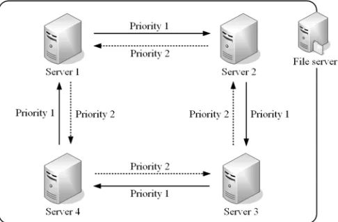
The proposed system is based on a management group, which is composed of servers offering services to clients, and each server belonging to the management group manages every other server. The construction of the basic management group in the proposed system is shown in Fig. 2. In the proposed system, one management group is based on four servers, and a management form, which manages one target server by two management servers, is adopted. A management structure, which manages each server with the server management priority order, is constructed by servers belonging to the group, as shown in the figure. If eight servers are set as target servers and management servers, two management groups are arranged.
[image:4.612.183.426.535.695.2]Servers 1 through 4 connect to the file server through NFS connection, and the shared area is allocated on each server. Two management programs, which have the server management priority order, are executed on each management server shown in Fig. 2. Server 1 manages Server 2 as server management priority order 1 (P1) and manages Server 4 as server management priority order 2 (P2). This priority is adopted in order to prevent a malfunction in the recovery processing. Here, management refers to monitoring the network and the state of service program on the target server, recovering the server function by starting the virtual server on the management server, recovering the target server by restarting the problem service program or the problem target server.
Management and Recovery Operation of the Server Management System Incorporating a P2P Method
Operation Flow of Each Server Management Priority Order
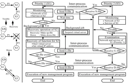
An operation flowchart of two server management priority orders is shown in Fig. 3. Servers S1 and S3 are management servers and S2 is the target server. The virtual server, S2b, is the backup server for recovering S2 function. Server S1 executes the management program as P1, and S3 executes the management program as P2. Both S1 and S3 regularly monitor the network and the service offer state of S2.
[image:5.612.155.428.526.706.2]Server S1 monitors S2 after S1 sends the S.file to S3 by inter-process communication, and S3 starts to monitor S2 when the S.file is received. If trouble is detected in S2, then S1 starts virtual server S2b after a background job is executed and sets the virtual IP address to S2b. Thereafter, S1 enters a wait state in order to find the up.file or the down.file, which is created by the background job. If S3 detects trouble in S2, then S3 enters a wait state in order to receive the U.file or the D.file, which is sent by S1. The up.file is created by the background job if S2 is judged to recover the function. If S1 finds the up.file, the U.file is sent to S3, and both S1 and S3 synchronously monitor S2 again. If S2 is judged not to be recovered by the background job, the down.file is created. If S1 finds the down.file, the D.file is sent to S3. New management programs are synchronously executed by S1 and S3 in order to manage the new target servers. The management programs to manage S2 are then terminated. Through the above-mentioned process, the management structure is automatically modified. We refer to as the dynamic management structure modification method.
Server Function Recovery Method
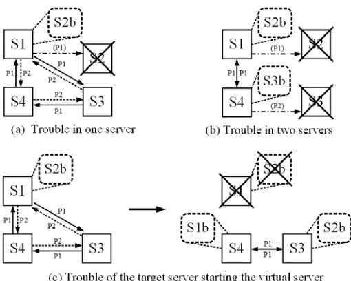
Figure 4 shows how to recover the server functions in the case of target server failure. S1, S2, S3, and S4 operate as both management servers and target servers. Servers S1b, S2b, and S3b denote virtual servers.
The recovery method for the case shown in Fig. 4(a) is described below. If management server S1 operating as P1 detects trouble in target server S2, S1 starts virtual server S2b and sets the virtual IP address to S2b. As a result, the function of S2 is recovered. In addition, if S2 is judged not to be recoverable by S1, the management structure is modified by the dynamic management structure modification method. Here, the management program operating as P1 on S4 does not detect trouble in S2. Thus, the management program operating as P2 on S3 reports the modification to S4.
Recovery by the management server operating as P1 and the management server operating as P2, as shown in Fig. 4(b), is described below. Management server S1 operating as P1 detects trouble in S2, and virtual server S2b is started on S1. Server S1 sets the virtual IP address to S2b and recovers the function of S2. However, since management server S2 operating as P1 is in an abnormal state, management server S4 operating as P2 detects trouble in S3, and virtual server S3b is started on S4. Server S4 sets the virtual IP address to S3b and recovers the function of S3. If S2 and S3 are judged not to be recoverable by the management servers, the management structure modifies the arrangement of two servers.
[image:6.612.178.433.485.689.2]The virtual server may start on the target server because each server has functions of both management and target servers. Figure 4(c) shows how to recover the server function when the target server starting the virtual server breaks down. Target server S1 starts virtual server S2b in order to recover the server function of S2. Therefore, the management structure incorporates three-server structures. At this point, a method of dealing with the condition in which S1 fails is shown below. Target server S1 is monitored by management server S4 operating as P1 and management server S3 operating as P2. If S1 fails, the proposed method recovers the server functions of both S1 and S2b by a special operation whereby management server S4 starts virtual server S1b, and S3 starts virtual server S2b. This special operation is adopted because the efficiency of the start operation for the virtual server is considered.
Operation Experiment on the Server Management System Incorporating a P2P Method
Experimental System
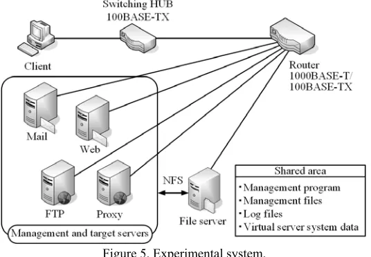
[image:7.612.173.441.360.546.2]The construction of the experimental server management system incorporating the P2P method is shown in Fig. 5. The experimental system consists of a mail server, a web server, an FTP server, a proxy server, a file server, a client, a router with a 1000BASE-T function, and a 100BASE-TX switching HUB. Each server, except for the file server, has functions of both management and target servers. In the network environment of the experimental system, the access speed from clients is set to one-tenth of the transfer speed between servers, as in a general network system. The executer program is installed on each management server and is executed. The management program, the management files, log files, and virtual server system data are saved in the shared area on the file server. Each management server uses these files through NFS connection. The servers, except for the file server, belong to the management group and manage each other. The operating state of the management program on each management server is recorded in the log file. In the experimental system, flag files on each management server are created or deleted by the file server. If the flag file is created in the local disk, the management program is executed. If the flag file is deleted, the executer program stops all management programs starting on the management server and stops the operation of the management server.
Figure 5. Experimental system.
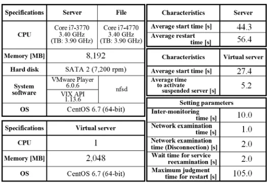
The specifications of the experimental system, the characteristics of each server as fundamental data, and the setting parameters when the system operates are listed in Table 1. The specifications of the four management servers are similar, and the CPU is a Core i7-3770. The memory size is 8,192 MB, in consideration of the start of virtual servers. VMware Player (Virtualization software) and VIX API, which has a function to start the virtual server on the server in an environment of a character-based user interface and a function to suspend the virtual server, are installed in each management server. The file server has a Core i7-4770 CPU and 8,192 MB of memory. One CPU and 2,048 MB of memory are assigned to each virtual server. CentOS (64-bit), which is often adopted as an OS for servers, is installed on each server.
the average start time of each management server is 44.3 s, and the average restart time of each management server is 56.4 s. In the virtual server, the average start time under the normal condition is 27.4 s, and the time to activate the suspended condition is 5.2 s. For this reason, the start time for the virtual server is shortened by this method. Therefore, the virtual server is always in a waiting state with a suspended condition in this system.
[image:8.612.175.437.248.429.2]In the setting parameters, the inter-monitoring time in the target server management is 10.0 s. Moreover, the network examination time when the target server network is normal is 1.0 s, and the network examination time when the target server network is abnormal is 2.0 s. Also, the wait time before reexamination after the service program restart is 2.0 s. The maximum time to determine whether the target server is in the restart state is 105.0 s.
Table 1. Specifications, characteristics, and setting parameters.
Experimental Results in the Case of Target Server Trouble
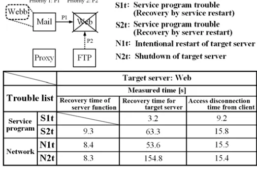
Experiments to reproduce trouble on the network or the service on the web server are performed. The inter-monitoring time is 10 s. Trouble is generated when the inter-monitoring time exceeds five seconds, and the time required for recovering the server function is measured. The service trouble is reproduced by stopping the service program on the target server, and the network trouble is reproduced by restarting or shutting down the target server.
As shown in Fig. 6, four types of trouble are defined. Here, S1t represents the condition in which the service function is recovered by restarting the service program. S2t represents the condition in which the service function is recovered by restarting the target server because the service function is not recovered by restarting the service program. N1t represents the case of an intentional restart of the target server, and N2t represents the condition in which the target server is shut down.
In the Recovery time of server function column, the recovery time for dealing with trouble in the case of S2t is 9.3 s, the recovery time for dealing with trouble in the case of N1t is 8.4 s, and the recovery time for dealing with trouble in the case of N2t is 8.3 s. The start time of the virtual server greatly affects the recovery time from trouble.
In the Recovery time for target server column, the recovery time for dealing with trouble in the case of S1t is 3.2 s, the recovery time for dealing with trouble in the case of S2t is 63.3 s. Moreover, the recovery time for dealing with trouble in the case of N1t is 53.6 s, and the recovery time for dealing with trouble in the case of N2t is 154.8 s. The server restart time greatly affects the recovery time in the case of S2t because the service function is recovered by server restart. The maximum judgement time and the server start time listed in Table 1 greatly affect the recovery time in the case of N2t because the web server is restarted after examining whether the server is in the restart state.
[image:9.612.174.435.321.493.2]In the Access disconnection time from client column, the recovery time for dealing with trouble in the case of S1t is 9.2 s, and the recovery time for dealing with trouble in the case of S2t is 15.8 s. The recovery time for dealing with trouble in the case of N1t is 15.5 s, and the recovery time for dealing with trouble in the case of N2t is 15.4 s. The inter-monitoring time and the network examination time are included in each recovery time.
Figure 6. Recovery times in the case of trouble in one server.
The server function recovery times are longer than the times in Fig. 6 because two virtual servers are started with approximately the same timing in order to recover two server functions. The start time required for two virtual servers is believed to be longer than that required for one server, even if virtual servers are started from different real servers, because the system data of virtual servers are saved to the shared area on the file server, and each management server starts virtual servers through NFS connection.
Figure 7. Recovery times for cases in which trouble occurs simultaneously in two servers.
Summary
We herein proposed a low-cost server management system incorporating a P2P method. In order to construct the proposed system, a server function recovery method using a virtual server to realize low cost and power savings in the P2P method, a server management priority order and a dynamic management structure modification method to continue management of servers that are not affected by trouble were proposed and described herein. An experimental server system using the proposed method was constructed, and the architecture was presented. Experiments to reproduce several types of trouble in the server system were conducted, and the recovery times of the target server function and the target server, which experienced trouble, were measured. The proposed system was found to be able to recover the server function or the target server even when troubles simultaneously occur on several target servers.
References
[1] C. Papagianni, A. Leivadeas, S. Papavassiliou, V. Maglaris, C. C.-Pastor, and A. Monje. On the Optimal Allocation of Virtual Resources in Cloud Computing Networks, IEEE Trans. Comput. Vol. 62 No. 4/6 (2013) 1060-1071.
[2] M. Kitamura and C. Fujihashi. Analysis of Response Time Characteristics of a Real Computer by Heterogeneous-Task Bursty-Arrival Models, IEICE Trans. Vol. J81-B-I No. 4 (1998) 243-253.
[4] H. Otsuka, K. Joshi, M. Hiltunen, S. Daniels, and Y. Matsumoto. Online Failure Prediction with Accurate Failure Localization in Cloud Infrastructures, IEICE Technical Report Vol. 113 No. 496 (2014) 7-12.
[5] J. Xiao, B. Wu, L. Zhang, H. Wen, X. Jiang, and P.-H. Ho. Joint Design on DCN Placement and Survivable Cloud Service Provision Over All-Optical Mesh Networks, IEEE Trans. Commun. Vol. 62 No. 1 (2014) 235-245.
[6] Q. Zhang, M.-F. Zhani, M. Jabri, and R. Boutaba. Venice: Reliable Virtual Data Center Embedding in Clouds, Proc. IEEE Inf. Vol. 1 (2014) 289-297.
[7] M.-G. Rabbani, M.-F. Zhani, and R. Boutaba. On Achieving High Survivability in Virtualized Data Centers, IEICE Trans. Commun. Vol. E97-B No. 1 (2014) 10-18. [8] W.-L. Yeow, C. Westphal, and U.-C. Kozat. Highly Available Virtual Machines with Network Coding, Proc. IEEE Inf. Vol. 1 (2011) 386-390.
[9] S. Wang, J. Lu, J. Chen, and X. Liu. PowerSleep: A Smart Power-Saving Scheme with Sleep for Servers under Response Time Constraint, IEEE Emerg. Sel. Top. Circuit. Syst. Vol. 1 No. 3 (2011) 289-298.
[10] Ministry of Economy, Trade and Industry,
http://www.meti.go.jp/committee/materials/downloadfiles/g80520c03j.pdf, May 2008. [11] Y.-C. Chen and C.-Y. Wen. Distributed Clustering with Directional Antennas for Wireless Sensor Networks, IEEE Sens. Jour. Vol. 13 No. 6 (2013) 2166-2180.
[12] S. O. D. Luiz, A. Perkusich, C. B. M. J. Cruz, B. H. M. Neves, and G. M. S. Araujo. Optimization of Timeout-based Power Management Policies for Network Interfaces, IEEE Trans. Consum. Electron. Vol. 59 No. 1 (2013) 101-106.
[13] L. Catarinucci, S. Guglielmi, R. Colella, and L. Tarricone. Compact Switched-Beam Antennas Enabling Novel Power-Efficient Wireless Sensor Networks, IEEE Sens. J. Vol.14 No.9 (2014) 3252-3259.
[14] T. Pan, T. Zhang, J. Shi, Y.Li, L. Jin, F. Li, J. Yang, B. Zhang, and B. Liu. Towards Zero-Time Wakeup of Line Cards in Power-Aware Routers, Proc. TEEE Infocom Vol. 1 (2014) 190-198.
[15] C. Lalit and K. Hemange. Formal Approach for DVS-Based Power Management for Multiple Server System in Presence of Server Failure and Repair, IEEE Trans. Ind. Inform. Vol. 9 No. 1 (2013) 502-513.
[16] M. Kitamura. Configuring a Low-cost, Power-saving Multiple Server Backup System: Experimental Results, IEICE Trans. Commun. Vol. E95-B No. 1 (2012) 189-197.