Systems Reference Library
On-Line Testing
IBM 1401, 1440, and 1460
This publication presents on-line testing procedures for a communication-oriented IBM 1401, 1440, or 1460
Data Processing System with a remote IBM 1050
Data Communications System and/or IBM 1030 Data
Collection System. Use of these procedures reduces the inconvenience caused by malfunctions external to the data processing system and the IBM 1026 or
1448 Transmission Control Unit.
The
lacs
options for on-line testing are discussed, and a typical user's diagnostic routine is described. Also, suggestions are given for: (1) operator testing procedures at the remote terminal; (2) content of a diagnostic test message; and (3) types of off-line performance reports.The reader should be familiar with the following SRL publications, depending on the system he has installed.
IBM 1050 Data Communlcations System, Form A24-3020 IBM 1030 Data Collection System, Form A24-3018.
For a data processing system with an IBM 1448:
IBM 1448 Transmission Control Unit, Form A24-3010 IOCS Specifications, IBM 1460 with IBM 1448
(1401/1460 Communications IOCS -1448/DDC),
Form C24·,3047
IOCS Specifications, IBM 1440 with IBM 1448 (1440 Communications IOCS -1448/DDC), Form C24-3024.
For a data processing system with an IBM 1026: IBM 1026 Transmission Control Unit, Form A24-3244 Communications IOCS Specifications, IBM 1401, 1440,
and 1460 with IBM 1026 and Direct Data Channel,
Form C24-3241.
Copies of this and other IBM publications can be obtained through IBM Branch Offices.
Address comments concerning the content of this publication to IBM Product Publications, Endicott, New York 13764.
Contents
Introduction ... "... 5
IOCS Procedures ... 6
Diagnostic Test Message ... "... 6
User's Diagnostic Routine ... "... 7
Suggested Routine ... 8
Remote Terminal Test Procedures ... 10
Malfunction ... 10
Daily Routine ... ... ... 10
Communication-oriented IBM 1401, 1440, and 1460
Data Processing Systems may have large numbers of people in direct contact with the system. Although these people are usually situated at locations remote from the central control of the system, they depend upon timely responses from the system for the efficient performance of their work. They must not be unduly delayed while waiting to communicate with the central files.
However, 1401, 1440 and 1460 systems that receive data from, or send data to, many remote locations are more susceptible to interruptions caused by malfunc-tions than are those systems that are not communica-tion-oriented. This is primarily due to the fact that more people and equipment are directly concerned with the total system operation. Remote terminals of an IBM 1050 Data Communication System and an IBM
1030 Data Collection System constitute most of the external components of an on-line IBM 1401, 1440, or
1460 system. These terminals, data sets, and lines cause the majority of the interruptions in a communi-cation system.
System interruptions may bring about widely vary-ing degrees: of inconvenience due to the type of failure and the component affected. Various levels of de-graded system operation may result, for example: • If one line is malfunctioning, service may be
main-tained to terminals on other lines.
• If one terminal is malfunctioning, service may be maintained to other terminals on the same line. • If one disk storage drive is inoperative, the disk
pack may be transferred to another drive if informa-tion on the alternate drive is not required for the operation.
Interruptions due to malfunctions external to the cen-tral system should be carefully considered and planned for during the early phases of system design, so that most of them can be isolated and restricted to the remote system (station) or communication line affected. When the system is in operation, information is pro-vided to the processing system for the detection of malfunctions as they occur. Intermittent malfunctions, such as parity errors, may be limited to momentary op-erational inconvenience, because machine features and programming systems permit detection and correction of errors and re-execution of operations when these malfunctions occur. However, when a malfunction
be-On-Li ne Testi n9
IBM 1401, 1440,
and
1460
comes repetitive and jeopardizes performance, correc-tive measures must be taken. During the servicing of the affected component, the nonafFected parts of the total system should remain operational.
A system plan that provides on-line testing for the isolation and analysis of a faulty line or station-compo-nent should be designed by the system analyst and programmer. On-line test procedures can be used with the IOCS program supplied by IBM, or the customer
can incorporate them in his own programming for the input and output of data from remote terminals. The on-line test features should be included to: 1. Reduce the inconvenience and time required for the
isolation and analysis of malfunctions external to the central processing unit and the IBM 1026 or 1448
Transmission Control Unit. The operator at the re-mote terminal can perform test functions before calling for customer engineering service, and the custom.er engineer can use the testing routines in his analysis. Because of the multiplicity of compo-nents attached to a single Hne (a data set at the
IBM 1026 or 1448, a data set at the remote station,
multiple components at the station, and possibly other stations with a data set and multiple compo-nents, as in a multipoint line), the customer engineer must first isolate the part of the system causing the malfunction. This usually necessitates the transmis-sion of test messages from the terminal, and the retransmission of the same message back to the same terminal, or to another terminal located nearby. The customer engineer can analyze the re-turned message for clues to the cause of the mal-function. He can vary the bit patterns of the test message and observe oscilloscope signals of the data characters. When he isolates the malfunction, he can correct it off-line without interrupting the op-eration of the nonafFected parts of the system. 2. Verify customer engineering corrective measures.
After he has located and corrected, off-line, any line or terminal error condition, the customer en-gineer can prove that the system is operating cor-rectly. He sends a message, which is recognized as a test by the central processing unit, and receives the retransmitted message on the same or nearby terminal for visual verification of the contents. This verification procedure may require the transmission of several messages.
loes
ProceduresThe IBM lacs routines provide two options for
hand-ling diagnostic messages entered from remote 1050 or 1030 terminals. When an IBM 1030 Data Collection
System is on-line, each IBM 1031 Input Station must
include a card reader.
In the first option, laCS completely handles the diagnostic operation: the message is received, recog-nized as a test message, edited, and transmitted back to the same terminal or another nearby terminal on the same line for visual verification. Whenever this option is used and an IBM 1030 Data Collection System is
on-line, each 1030 line must have an IBM 1033 Printer
available to print the message that is sent back from the central location.
In the second option, the message is received and recognized as a test message. Then lacs provides a branch to the user's diagnostic routine. In his routine the user may include whatever programming he de-sires to process and edit the message, record it for fu-ture analysis, and transmit it back to a remote terminal.
Both options require the DIOCS entry MPXDIAG. A five-character flag must be specified in this entry. During operation lacs compares this Rag with the first five characters of each message received or trans-mitted by the 1026 or 1448. When they are the same, the message is recognized as a diagnostic test message. The second option requires a second operand in the MPXDIAG entry. This operand is the label of the programmer's diagnostic routine.
The number of core-storage positions needed to handle this on-line diagnostic test function is relatively small, and varies with the laCS option that is used.
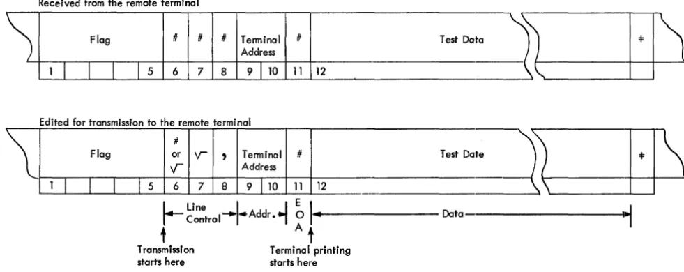
Received from the remote terminal
~
Flag # # # Terminal #Address
1 1 1 1
I
5 6 7 8 9110
1112
Edited for transmission to the remote terminal
\
#Flag or 'V
,
Terminal #V Address
1
I I I
r 5 6 7 8 9TlO 1112
The 1448 lacs requirements are approximately:
Option 1 170 positions Option 2 140 positions
The 1026 laCS requirements are approximately:
Option 1 400 positions Option 2 '140 positions
When Option 2 is selected, additional storage posi-tions are needed for the user's diagnostic routine.
Diagnostic Test Message
For both laCS options, the recommended format of the diagnostic test message is the same, but the func-tions performed by lacs differ. The diagnostic test message (Figure 1) should contain:
Positions Contents
1-5 Diagnostic flag (Any digits, letters, or special char-acters except =1=, $,
.y--,
and blank. These char-acters correspond to 1052 keyboard charchar-acters EOB, Delete, EaT, and Space.)6-8 On input, 3 characters must be received from the terminal. They may be any digits, letters, or special characters except:
=1=, $, and
V-
for the 1050=1=, $,
V ,) ,
and blank for the 1030 For output, lacs edits line-control codes into these positions.9-10 Terminal (station-component) address on this line to which the data processing system, with the 1026 or 1448, should transmit this test message for visual verification at the terminal.
11 End-of-address (EOA) character (#).
Test Do
Test Do
L...
Line -'J
EI
I
Controli'-
Addr •i
0 ...1'---
Datat A t
Transmission Terminal printing
starts here starts here
Figure 1. Diagnostic Test Message (for 1050) in Core Storage
[image:6.615.54.545.483.678.2]Positions
12-xxx
xxx+1
Contents
Test data (Any number of characters up to the number of core-storage positions alloted for this line, minus 12. The complete diagnostic message read into storage from the terminal consists of the first 11 characters, this test data, and the end-of-block character.)
End-of-block (EOB) character (=1=).
When this message is received, the functions per-formed by laCS are:
Option 1 -- 1448 10CS
1. The incoming message is recognized as a diagnostic test message by the flag in positions 1-5. laCS examines all messages for this flag.
2. laCS edits the message in the input area in which it was received, as follows:
a. Position 6. A positive-response code (# for 1050; • for 1033) to indicate that the message was
re-ceived without error; or a negative-response code ( y ' for 1050; - for 1033) to indicate that an error was detected.
b. Position 7. A
V
character to place station-components on this line in LINE-CONTROL mode. c. Position 8. An address-select code (,) to place station-components on this line in ADDRESS-SELECTmode.
3. laCS initiates transmission of the message (starting with position 6) to the terminal specified in positions 9 and 10 of the received message. The diagnostic flag is not transmitted.
4. When this line changes to any END-OF-BLOCK status, laCS restores it to polling status (RECEIVE-CONTROL).
Option 2 -- 1448 10CS
1. The incoming message is recognized as a diagnostic test message by the flag in positions 1-5. laCS examines all messages for this flag.
2. laCS makes the following transmission information available for the user's diagnostic routine:
Line Number Line Status
Incoming Message (Address) Line Control Field (Address) Auxiliary Control Field (Address) Length of the Message
Flag to indicate if any outgoing messages are stacked for this line.
This is the same information that is available for any user's routine at an end-of-block (EOB) con-dition.
3. laCS transfers control to the user's diagnostic rou-tine by branching to the label specified as the sec-ond operand in the DIOCS MPXDIAG entry. In his routine the user usually records the diagnostic test message, edits it, and transmits it back to the terminal.
4. At the end of his routine the user must transfer con-trol back to laCS, by issuing a RELSE macro. 5. When a message has been transmitted to the
ter-minal (TRANSMIT status) and an EOB condition is
detected, laCS again checks the first five characters of the message. If they contain the flag, control is again transferred to the user's routine. This permits the user to record the message as it was transmitted.
6. At the end of his routine, this time, the user should issue a POLL macro before he issues the RELSE macro to return control to IOCS.
Options 1 and 2 - 1026 10CS
The options are similar for 1026 laCS, except for ac-knowledgment procedures on 1030 lines. On these lines the procedures should provide for a GOOD or ERROR macro followed by a PUT macro. The first character of the message being retransmitted should be a
V
(EaT).User's Diagnostic
RoutineThe second option offered by laCS has the potential of providing the user with valuable information for immediate diagnostic purposes, for audit-trail records, and for future analyses of component operation. In his own diagnostic routine the user may record at the central location any data that is useful to him, as well as transmitting the message back to the terminal.
A complete printed record of the diagnostic test mes-sage aids in the isolation and analysis of the system malfunction. It also assists the operator at the central location in determining whether customer engineering service is required at the central location or at the terminal. For a thorough evaluation of an error condi-tion, the complete diagnostic test message should be printed twice at the central location: first, exactly as it is received from the terminal; and second, after it has been transmitted back to the terminal. Along with the message, the printout should include the:
• line number • line status
• station-component address from which the mes-sage was received.
• date and time (if available)
Most on-line systems must provide an audit trail of transactions, to maintain the necessary accounting con-trols of on-line activities. To make this sequential rec-ord complete, diagnostic test messages, as well as reg-ular messages, should be recorded on the medium (tape or disk) established for the audit trail. In addi-tion to fulfilling the accounting requirements, these audit-trail records of the diagnostic test messages can also be used for off-line analyses of malfunctions. They can be selected periodically from the complete set of audit records and used for various reports (see Off-Line
Performance Reports).
For both the accounting requirements and the per-formance studies, the tape or disk record should in-clude the same factors that are printed for the im-mediate evaluation. Therefore, the user's diagnostic routine should provide the programming to record the complete message, line number, line status, station-component address from which the message was re-ceived, date, and time.
Whenever the user selects IOCS Option 2 and writes his own routine, he can handle diagnostic test mes-sages from an IBM 1030 Data Collection System even though the system does not include an IBM 1033
Printer. (IOCS Option 1 requires a 1033 to print the message at the terminal location.) Messages received from a terminal can be printed for analysis at the central location, and a signal can be sent back to the remote terminal to indicate that the message was re-ceived correctly, or incorrectly. Following the trans-mission of a good or an error acknowledgment signal from the central location, the system can be restored to polling status. Normal service is restored to all 1030 terminals on the line.
8 On-Line Testing, 1401, 1440, 1460
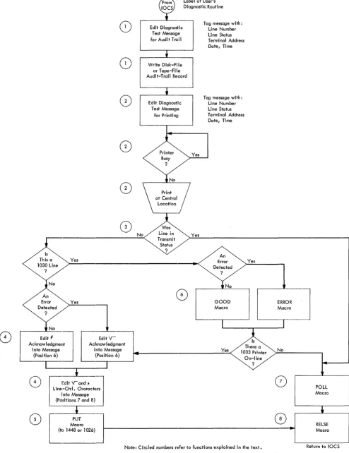
Suggested Routine
The functions suggested for a comprehensive user's routine are illustrated schematically in a flowchart (Fig-ure 2). IOCS branches to this routine either once or twice for each diagnostic test message: first, when the diagnostic test message has been received from a ter-minal; and second, after the message has been trans-mitted back to a 1050 terminal or to a 1030 terminal that has a 1033 on-line. If a 1033 is not available, IOCS branches to this routine only once. The functions in-cluded in this routine are:
1. Edit the message (as received or transmitted) with pertinent information, such as line number, line status, terminal address, date, and time; and record it for the audit trail.
2. Edit the message (as received or transmitted) with pertinent factors and print it for immediate analysis. 3. Determine whether the message has just been
re-ceived or transmitted.
4. Edit the proper acknowledgment (good or error) and line-control characters into a received message that is to be transmitted back to the terminal. After transmission', these characters are part of the mes-sage as it is recorded (1) and printed (2) at that time.
5. Transmit the message.
6. Send an acknowledgment (good or error) back to the terminal when the received message is not to be transmitted.
7. Return the system to polling status:
a. After a transmitted message has been recorded and printed.
b. After an acknowlegment has been sent for a
<
<
Error Detected?
8
8
0
Yes
Yes
Mn!:;~m.nJ [Ckn~:~e~m.
entinto Message into Message
(Position 6) (Position 6)
c-=_-.-___ ...
(~
(~
,
Edit V-and,
J
Line-Ctrl. CharactElrs into Message (Positions 7 and 8)
Macro
Label of User's Diagnostic Routine
Ed;, Test Message
mag""U
for Audit TrailWrite Disk-File or Tape-File Audit-Trail Record
Ed;,
o;agno"j
Test Messagefor Printing
Tag message with: Line Number Line Status Terminal Address Date, Time
Tag message with: Line Number Line Status Terminal Address Date, Time
An
GOOD Macro
Yes
Yes
On-line ?
No
o
ptT
]
(to 1448 or 1026) 1 - - - + 1
Note: Circled numbers refer to functions explained in the text.
Figure 2. Flowchart of User's Diagnostic Routine
POLL Macro
RELSE Macro
Return to 10CS
[image:9.613.67.561.65.707.2]Remote Terminal Test Procedures
Malfunction
The operating procedures to transmit a diagnostic test message from a remote terminal vary with the terminal in use. In an IBM 1050 Data Communication System a message may be sent from a 1052 Keyboard (Figure 3), a 1056 Card'Reader (Figure 4), or a 1054 Paper-Tape Reader (Figures 5 and 6). In an IBM 1030 Data
Collec-tion System, the message may originate from the card reader at the 1031 Input Station.
A suggested diagnostic test message that can be entered by the keyboard, or prepunched in a card or paper tape is:
C ' ) . ' . E
~ ~ §..c; 0
Flag ~D ~~ A / ,~".-..~
q d i a g # # # a l # N L
Test { abc d e f g h i j kim n 0 p q r s t Data u v w x y z 1 2 3 4 5 6 7 8 9 0 =F
qdiag = Recommended flag
Term Addr. = Address of the terminal to which the central location should send back the message.
NL
=
New Line (Carriage Return and Line Feed)The error procedures shown in each illustration ap-ply only if the flag portion of the message contains an error and, therefore, cannot be recognized by the pro-gram at the central location.
A paper-tape reader that has the automatic tape reread special feature installed requires a carrier-return .character (8-channel punch) at the beginning of each message in the tape. This stops reverse feeding on an error condition. Therefore, the diagnostic test message must contain NL as its first character, and NL must not be included elsewhere within the message. Also, the operator must be sure that the Printer 1
switch is set to RCV (Figure 6), and that the printer is positioned so that typing will start at the beginning of the line when the message is sent back from the central location. For this terminal, the diagnostic test message should be:
C ' ) . ' . E
~ ~ §~ 0
Flag ~D ~~ A
" \~/'>.."...
NL q d i a # # # a 1 #
Test {a b c d e f g h i j kIm n 0 p q r s t Data u v w x y z 1 2 3 4 5 6 7 8 9 0 =F
Daily Routine
To minimize the occurrence of error conditions during operation, it is recommended that each morning,
be-10 On-Line Testing, 1401, 1440, 1460
fore operation is started, the operator perform the terminal testing provided by the test switch on the
IBM 1052 Printer-Keyboard. This feature provides a closed-loop test of the terminal itself and helps the operator establish whether the terminal is operating satisfactorily. The procedure for performing this test is described in the SRL publication IBM 1050 Data Communications System, Form A24-3020.
Off-Line Performance Reports
To assist in maintaining continually satisfactory per-formance by the total system, perper-formance reports should be prepared and analyzed on a regularly sched-uled basis. These reports provide valuable planning information about system· traffic and system errors. They can be easily prepared, off-line, from the records that are written in the audit-trail file as transactions are processed.
The amount of over-all system traffic can be shown by reports that give traffic volumes by line, by station-component, and/or by time of day. Analysis of these reports provides information vital to effective planning for improvements in general system operation and for future expansion of communication facilities, terminals, and terminal features.
Reports of errors can supply information about hu-man data errors and about errors resulting from system malfunctions. Analyzing the types of data errors aids in detecting any procedural shortcomings that may be prese;nt at the remote terminals. Reports of system-malfunction errors can be obtained from the diagnostic test messages that are included in the complete set of audit-trail records. These reports should be listed by line, by station-component, and/or by time of day. If
they are prepared frequently, operating management will become aware of intermittent malfunctions during the early stages of failure. At that time, malfunctions can be corrected with the minimum of inconvenience to the user. The reports provide the IBM customer
engineer with valuable information for the isolation and analysis of the error conditions.
For the preparation of various performance reports, as well as for a complete audit, the audit-trail records should contain the:
• .complete message • line number • line status
• station-component address from which the mes-sage was received, or to which the mesmes-sage was transmitted from the central location.
IBM
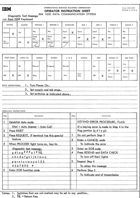
INTERNATIONAL BUSINESS MACHINES CORPORATIONOPERATOR INSTRUCTION SHEET
Do ° T M IBM 1050 DATA COMMUNICATION SYSTEM lagnostlc est essage
JOB from.lQ52 Keyboard
SYSTEM MASTER PRINTER J PRINTER 2 KEYBOARD RDR J RDR 2
-On Ree Ree Send X Send Send Attend
X 1 -
-- r - - - ')end Send
Off Off Off Ree X Ree X
Un-Off X -
-attend
Z
Z
7
Home Home Send SendSTOP CODE AUTO Fill PUNCH SYSTEM E 0 B SYSTEM TEST
-_._-I
Sense On Normal Program Manual On
-
_._-
--Off )( Off X Bksp Dup Aulo Dial Disc Off SETUP INSTRUCTIONS 1. Turn Power On.
2. Set margin and tab stops.
~l. Set switches as indicated above.
OPERATING INSTRUCTIONS
Step Description Step
PUNCH J Ree.
X Off
Home SINGLE CY line Off X
X Home
Description
Form X24-3139
Printed in U. S. A. PUNCH 2 Ree. Off Home
RDR STOP line Off X Home
Estclblish datel mode KEYI NG-ERROR PROCEDURE.2,,_F_..:LA=:'-'---=.G _ _ ----t
2
3
Dial - Autc) Answer - Auto Call Press RESET
Press REQUEST, if terminal has th is soecial feature
If a kevina error is made ~S1:.eP--Alnihe-- ____ _
flag portion (q d i a g): Do not perform Step 5 2 Enter a CANCEL code 4 When PROCEED light turns on, key-in To indicate the error
diagnostic test message: 3 Enter an EOB code
9 d i a g # # # a 1 # NL 4 Press RESEND and DATA C_H_E.-'-C_K. ______ - - I 01 b c d e f g h i
i
k I rn n 0 To tu rn 0 ff the i r I i gh t~ ..I----+_~p-.-::g~r ~s...!.t~u~v!...!w~x'_,yl___=_z'---'--l ~2'__.!3~ _ _ _ _ _ _ _ _ +t__=5--t-=Rc.:..:e::.J:lP=(e::...::a'-'-t--'S::..:.te~lo~4'---~ ... _. ___ _
4567890 =1= To rekey the messaQe
5 Enter EOB function code 6 Perform Steo 5
To indicate end of transmission
Notes: 1. Switches that are not marked may be set in any position. 2. NL = Return Key
Figure 3. Test Message Sent from an IBM 1052 Keyboard
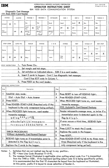
[image:11.613.70.531.41.689.2]INTERNATIONAL BUSINESS MACHINES CORPORATION
IBM
OPERATOR INSTRUCTION SHEET Form X24·3139 Printed in U. S. A.IBM 1050 DATA COMMUNICATION SYSTEM
Diagnostic Test Message
JOB from ] 056 Card Reader
SYSTEM MASTER PRINTER 1 PRINTER 2 KEYBOARD RDR 1 RDR 2 PUNCH 1 PUNCH 2
Attend
Un-attend
X
~end
f
n ReeRee ----<"---Off X Ho,:/,
X
/send
Rec
Send
Ree
~--/Send
Send
Off
Send Send X Ree. Ree.
Off X Off Off Off
Home Home Home Home
STOP CODE AUTO FILL PUNCH SYSTEM E 0 B SYSTEM TEST SINGLE CY RDR STOP
I
*
Line
*
t
Normal Program Manual
f t
Off X DialOff X Off X Bksp Dup Auto Disc Off X
Home Home
SETUP INSTRUCTIONS 1. Turn Power On.
2. Set margin and tab stops.
3. Set switches as indicated above. RDR 2 is a card reader. 4. Insert 2 cards in hopper: Card 1 has diagnostic test message;
Card 2 has EOT code in Column 1 • 5. Press FEED on the card reader.
OPERATING INSTRUCTIONS
Step Description Step Description
Establish data mode: 3 Press RESET to turn off RESEND liaht. Dial - Auto Dial - Auto Answer 4 Press READER-START -LI NE.
1-2_+P_r_e_ss_R_ES_E_T...:. _ _ _ _ _ _ _ _ _ _ _ _ _ _ H--5----1I---'Wh-'----e::..::n~P.:..:.R_=0...:C::..:E::::E:.::D:...:..:.:I ight turns on I card reader
3 Press READER-START-L1NE (Required only if the transmits messaQe.
keyboard is the on Iy component being polled). With Automatic Card Reread Feature:
4 When PROCEED liaht turns on. card reader Reader retransmits messaQe once. or twice if a transmits messaQe: transmission error is detected aQain in the
q d i a g # # # a 1 # NL flag (q d i a g ).
abcdefQhiiklmnooars 2 If error occurs a third time. RESEND liaht
tuvwxyz1234567890 =I: turns on.
3 Press EJECT to stack the 2 cards. ERROR PROCEDURES 4 Replace the cards in the hoooer. Without Automatic Card Reread Feature:
5 Press RESET.
RESE ND light turns on if transmission error is 6 Press READER-START -L1 NE to try three more detected in the flag (q d i a g ). times (Required only if the keyboard is the 2 Replace the 2 cards in the hopper. only component being polled).
Notes: 1. Switches that are not marked may be set in any position. 2. NL
=
New Line Code (Punched 11-5-9).3. The message format illustrated is applicable when polling select code 0 or 7 is transmitted from the 1448 or 1026. If the keyboard (polling select code 5) is being specifically polled, it is recommended that the first 12 characters be keyed from the keyboard as illustrated. At this point, prefix 0 is keyed to cause selection of Reader 2.
Figure 4. Test Message Sent from an IDM 1056 Card Reader
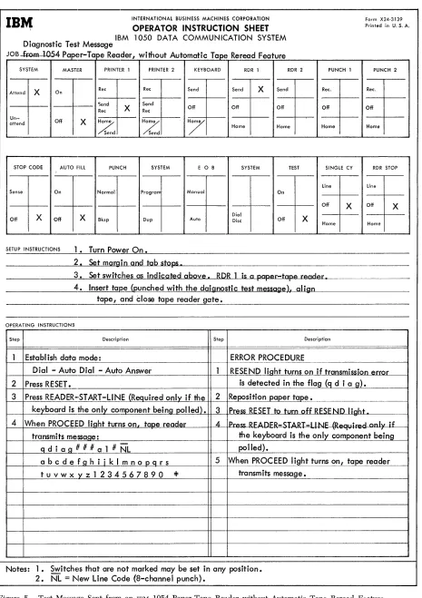
[image:12.615.57.486.45.703.2]INTERNATIONAL BUSINESS MACHINES CORPORATION
OPERATOR INSTRUCTION SHEET
IBM
IBM 1050 DATA COMMUNICATION SYSTEM
Diagnostic Test Message
JOB.Ja:om.--1054 Paper-Tape Reader, without Automatic Tape Reread Feature
SYSTEM MASHR PRINTER 1 PRINTER 2 KEYBOARD RDR 1
-,..._-
-RDR 2 Attend X On Ree Ree Send Send X Send
1 -
-- 1 - . _ - Send
X Send Off Off Off Ree Ree
Un-Off X
Z
Z
7
attend
Home Home Send Send
STOP CODE AUTO 1:lll PUNCH SYSTEM E 0 B SYSTEM TEST
~,...--Sense On Normal Program Manual On
- 1 - ' _ -I
-X X Dial X
Off Off Bksp Dup Auto Disc Off SETUP INSTRUCTIONS 1. Turn Power On.
2. Set margin and tab stops.
PUNCH 1 Ree. Off Home
SINGlE CY Line Off X Home
3. Set switches as indicated above. RDR 1 is a paper-tape reader, 4. Insert tape (punched with the daignostic test message). align
tape, and Close tape reader gate.
OPERATING INSTRUCTIONS
Step Description Step Description
Establish data mode: ERROR PROCEDURE
Form X24-3139
Printed in U. S. A. PUNCH 2 Ree. Off Home
RDR STOP line Off X
Home
Dial - Auto Dial - Auto Answer 2 Press RESET.
RESEND liaht turns on if transmission error is detected in the flag (q d i a S).
j...::3--J..:P~r.=::e.::ss::...:R~E~A~D::..E~R~-.~·S~T!.-A~R:..!.T_-L~I~N..::'~E~~ (IR~teQ~u~i r~e~d~o~n~IYl-!-if!...!!th~e~-=2=-+~Re.:=.Jpo=-=-=s.:..::it..:..:i o::..:n~pa=:Jp::..::e::..:r-=t~a.J::-pe~. _____________ _ ke!yboard is the only component being polled). 3 Press RESET to turn off RESE ND IighLLt _____ - - I 4 When PROCEED light turns on, taDe reader 4 Press RFtd)I=R-,TART -111\..11: (R.::.rtll;r.::.,.1 onlv if
tr<lnsmits message: the keyboard is the only component being
1---+ _ _ ..::J9L..:d::...::...i =a..>:;lg'--...#_# _#...."a"---.!...l -#-.N-"L"'---H--lr-- po lied).
abcdefghijklmnopqrs 5 When PROCEED light turns on, ta reader
tuvwxyz1234567890 ~ transm its message.
Notes: 1. Switches that are not marked may be set in any position. 2. NL = New Line Code (8-channel punch).
Figure 5. Test Message Sent from an IBM 1054 Paver-Tape Reader,without Automatic Tape Reread Feature
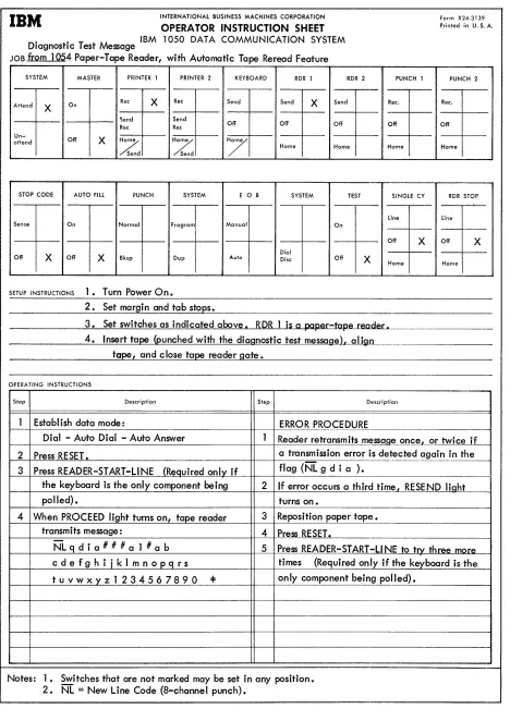
[image:13.612.69.534.47.706.2]IBM
INTERNATIONAL BUSINESS MACHINES CORPORATION Form X24·3139 OPERA TOR INSTRUCTION SHEET Printed in U. S. A.Diagnostic Test Message IBM 1050 DATA COMMUNICATION SYSTEM JOB f[Qm
1
054 Paper-Tape Reader, with Automatic Tape Reread FeatureSYSTEM MASTER PRINTER 1 PRINTER 2 KEYBOARD RDR 1 RDR 2 PUNCH 1 PUNCH 2
On Rec X Rec Attend
X Send Send X Send Ree. Ree.
'iend Send
Off Off Off Off
Ree Rec Off
Un-Off X
Z
Z
7
attend
Home Home Home Home Send Send
STOP CODE AUTO FILL PUNCH SYSTEM E 0 B SYSTEM TEST SINGLE CY RDR STOP
I
Line lineSense On Normal Program Manual On
Off X Off X Dial
Off X Off X Bksp Dup Auto Disc Off X
Home Home
SETUP INSTRUCTIONS l. Turn Power On.
2. Set margin and tab sto~s.
3. Set switches as indicated above I &D& 1 is a paper-tape reader.
4. Insert ta~ (punched with the diagnostic test messagelt aligo
tape land c lose tape reader gate.
OPERA TlNG INSTRUCTIONS
Step Description Step Description
1 Establ ish data mode: ERROR PROCEDURE
Dial - Auto Dial - Auto Answer 1 Reader retransmits message once
l or twice if
2 Press RESET. a transmission error is detected again in the
3 Press READER-START -LINE (Required only if flag (NL g d i a ).
the keyboard is the only component being 2 If error occurs a third timel RESEND light
polled) • turns on.
4 When PROCEED light turns on, tape reader 3 Reposition paper tape.
transmits message: 4 Press RESET.
NL q d i a # # # a 1 # a b 5 Press READER-START-L1NE to trx three mQre
cdefghiiklmnopqrs times (Required only if the ke~board is the
tuvwxyz1234567890
...
only component being polled).Notes: 1. Switches that are not marked may be set in any position. 2. NL
=
New Line Code (8-channel punch).Figure 6. Test Message Sent from an IBM 1054 Paper-Tape Reader, with Automatic Tape Reread Feature
[image:14.612.54.522.47.698.2]READER'S SURVEY FORM
On-Line Testing--IBM 1401, 1440, and 1460
Form C24-3341-0
• Is the material: Easy to read? Well organized? Fully covered? Clearly explained? Well illustrated?
Yes
o
o
o
o
o
SaUsfactory
o
o
o
o
o
• How did you use this publication?
As an introduction to the subject
0
For· additional knowledge of the subject 0
• Which of the following terms best describes your job?
Customer Personnel IB!M Personnel
Manager
D
Customer Engineer0
Systems Analyst
0
Instructor0
Operator0
Sales Representative0
Programmer0
Systems EngineerD
Trainee
0
Trainee0
Other Other
-• Check specific comment (if any) and explain in the space below:
(Give page number)
No
o
o
D
D
o
o
Suggested Change (PageD
Suggested Addition (Page )D
Error (Page )0
Suggested Deletion ( Page )Explanation:
Fold
BUSINESS REPLY MAIL NO POSTAGE NECESSARY IF MAILED IN THE UNITED STATES
Attention: Product Publications, Dept. 171
POSTAGE WILL BE PAID BY . .
I BM Corporation
P. O. Box 6
Endicott, N. Y. 13764
FIRST CLASS PERMIT NO. 170 ENDICOTT, N. Y .
•
Staple
Fold
---Fold Fold
C') c
o
<
C24·3341·0
~d]5lliJ
®
International Business Machines Corporation Data Processing Division
112 East Post Road, White Plains, N.Y. 10601
....
o
....
~
Q