University of Huddersfield Repository
Rubio Rodriguez, Luis and De la Sen Parte, Manuel
An Expert System for Mill Cutter and Cutting Parameters Selection
Original Citation
Rubio Rodriguez, Luis and De la Sen Parte, Manuel (2005) An Expert System for Mill Cutter and
Cutting Parameters Selection. In: Advances in Computer, Information, System Sciences and
Engineering. Proceedings of IETA 2005, TeNe 2005 and EIAE 2005 (XVI). Springer, London, UK.
ISBN 9781402052613
This version is available at http://eprints.hud.ac.uk/id/eprint/16023/
The University Repository is a digital collection of the research output of the
University, available on Open Access. Copyright and Moral Rights for the items
on this site are retained by the individual author and/or other copyright owners.
Users may access full items free of charge; copies of full text items generally
can be reproduced, displayed or performed and given to third parties in any
format or medium for personal research or study, educational or notforprofit
purposes without prior permission or charge, provided:
•
The authors, title and full bibliographic details is credited in any copy;
•
A hyperlink and/or URL is included for the original metadata page; and
•
The content is not changed in any way.
For more information, including our policy and submission procedure, please
contact the Repository Team at: [email protected].
An Expert System for Mill Cutter and Cutting
Parameters Selection
Luis Rubio* and M. De la Sen**
Instituto de Investigación y Desarrollo de Procesos Facultad de Ciencia y Tecnología, Campus Leioa Universidad del País Vasco Apdo.644, Bilbao,Spain
* [email protected] ** [email protected]
Abstract—This paper discusses the selection of tools in milling processes. To carry out this research, it has been developed an expert system based on numerical methods. The expert system, chooses an appropriate tool, between a known set of candidate available cutters. The knowledge base is given by limiting the process variables. They are obtained taking into account, instabilities due to tool-work-piece interaction, which are called chatter vibration, and the power available in the spindle motor. Then, a tool cost model is designed as pattern, which is then used to decide the suitable cutting tool. Once the cutting tool is selected, the optimal cutting parameters are calculated. To obtain those parameters other two cost function are designed, which are dependent on the frequency and on time domain output signal properties. An example is presented to illustrate the method.
Keywords; cutter selection, milling, expert system, chatter.
I. INTRODUCTION
Machining, in particular milling operations, is a broad term used to define the process of removing material from a work-piece. Furthermore, the milling operation process planning is required, nowadays, to increase its productivity, reducing cost and improving the final product [1].
This paper brings forward the concept of selecting an appropriate mill cutter, among a known set of candidate cutters, and obtaining the adequate cutting parameters for milling operations through an expert system.
There are several versatile approaches for tool and/or cutting parameter selection based on expert systems on manufacturing environments. Wong and Hamouda [2] developed an on-line fuzzy expert system. The system inputs the tool type, the work-piece material hardness and the depth of cut, and control the cutting parameters at the machine, as output. Cemal Cakir et al. [3] explained an expert system based on experience rules for die and mold operations. In that paper, the geometry and material of the work-piece, tool material, tool condition and operation type are considered as inputs. Then, the system provides recommendations about tool type, tool specifications, work-holding method, type of milling operation, direction of feed and offset values. Vidal et al. [4] focused on the problem of choosing the manufacturing route in metal removal process. They select the cutting parameters by optimizing the cost of the
operation taking into account various factors, such as, material, geometry, roughness, machine and tool. Carpenter and Maropoulus [5] designed a system, which provides reliable tool selection and cutting data for a range of milling operations. The method employs rule based decision logic and multiple regression techniques for a wide range of materials. This paper brings forward the concept of scheduling an appropriate cutting tool and the optimal cutting parameters through an expert system for milling processes.
The knowledge base of the expert system is based on numerical methods. The stability-lobes-diagram gives the stability boundary against the chatter vibration. The time domain simulation obtains the outputs variables, for given cutting parameters.
The expert system is instructed with the characteristics of the candidate tools. According to power consumption, chatter vibration avoidance and stability requests, a suitable tool is selected based on a defined tool cost model and selection criterion.
Once, the cutting tool is selected, the cutting parameters are obtained for the given tool configuration. Other cost function is designed. It is composed by the above mentioned cost function and other two cost function, based on time and frequency domain system response. Normally, the weight of those functions is less than the first one. Thus, the expert system selects a tool among the candidates, as well as the appropriate cutting parameters for it.
[image:2.612.365.494.589.694.2]II. SYSTEM DESCRIPTION
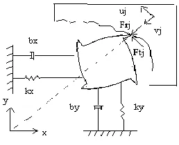
It has been developed a milling model, which assumes the cutter to have two orthogonal degrees of freedom and the work-piece to be rigid, as it can be seen in Figure 1.
A. Dynamic model
The dynamic model of the milling cutter is assumed to be a system with one mode of vibration in each direction xand y, while the feed direction is along the x- axis. The milling cutter has ntteeth, which are equally spaced. The dynamics of the system is given by the differential equations,
t t n j y yj y y y n j x xj x x x t f f y k y c y m t f f x k x c x m 0 0 where mi, ci, kiare the mass, damping and stiffness of the model in each direction, fxjand fyjare the components of the
cutting force that is applied by the jthtooth, which are obtained by projecting f into the two orthogonal axis.
B. Cutting force model
The cutting force model express the tangential component to be proportional to the instantaneous chip thickness, the axial depth of cut b, and the specific resistance of the material to be removed kt,
t t
F k b h (2)
The radial component of the force is,
r r t
F k F
where kris a proportional constant, k kt, r0.
C. Chip thickness model
The chip thickness is the most critical parameter because not only does it change with the geometry of the cutting tool and the cutting parameters, but also with the uneven surface left by the previous passes of the cutting tool. The resulting instantaneous chip thickness consists of a static part,
j t
s sin , attributed to the rigid body motion of the cutter, and a dynamic component caused by the vibrations of the tool at the present jand previous tooth period, jo. The total chip thickness can be obtained by,
j
jo j j t
j s g
h sin
where g
j is a step function, which determines whether the tool is in or out of cut [1,7].D. Time domain simulation
Since the system is excited by cutting forces that can not be expressed by simple analytic functions, the equations can not be integrated in a closed form. Thus, the 4th order Runge-Kutta method is employed to solve the differential equation (1) [4,7]. A simulation system, which reads the input data of cutting conditions, machine tool characteristics, and other related parameters, and calculates the applied forces and outputs the vibration displacements of chatter in milling, has been developed.
E. Stability lobes
In order to analyze the stability of the system, the transfer
function matrix,
i
, which gives the resulting displacements under the influence of the external forces, is considered. Since the xand ydirections are considered to be orthogonal, the cross terms are zero, xy yx 0. Withthose assumptions the eigenvalues of the system are obtained and the stability lobes calculated [1,2,7]. Then the following eigenvalue equation is to be considered [1],
0det I o ic
where o
ic is defined as the oriented transfer function matrix, which is obtained multiplying the milling force coefficients matrix and the transfer function matrix, as it is shown in [1]. The eigenvalue, of the characteristic equation (5) is,
1
4 c i T t t n
b k e
where crepresents chatter frequency, and T is the tooth period. The eigenvalue , of the previous equation can be easily solved for a given chatter frequency cstatic cutting
factors, kt, kr, which can be stored as material dependent quantities for any milling cutter geometry, radial immersion, and transfer function of the tool and work-piece system. Then, the stability lobes are calculated plotting the expression of chatter-free axial depth of cut, blim, versus spindle speed,
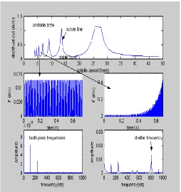
s
Figure 2. The chatter vibration representation in milling system, stability chars, force time response and force frequency response.
III. EXPERT SYSTEM
A. Milling process determination and preliminary rules
To carry out the tool selection and the determination of the values of the machining parameters, the milling process is determined. This paper is referred to two limitations. First, it is required the avoidance of the chatter vibrations. The productivity is given by a parameter known as metal removal rate (MRR). If the MRR is increased beyond a certain limit, self-excited vibrations are appreciated. This instability condition is characterized by a large level of vibration, poor surface finished and, usually, damage to machine tool components. The second limitation is given by the spindle power availability in the spindle motor. It delimits certain combinations of input variables, such as depth of cut, feed rate and spindle speed. This parameter bounds MRR as well. With those constrains, the “input space” can be obtained.
Due to uncertainties in the model, the lobes are constructed, not by replacing pure imaginary roots into the characteristic equation, but adding a positive real number to them. To have a robust system, it has been taken into account a confine in a programmed maximum depth of cut as well.
Then the following algorithmic methodologies are used, which are called preliminary rules:
Rule 1: Stability margin to ensure that the system plays in a stable region due to uncertainties in the model.
o Rule 1.1
A small stability margin is selected for calculating the border line in the lobes char. For that reason it is added a
positive real number into characteristic equation when the lobes are calculated, i.e, i i , 0. In this way, a stability threshold is considered against a possible bad modeling of the system.
o Rule 1.2
A margin at the final expression for chatter free axial depth of cut, which improves the robustness of the system, is taken into account. It can be expressed mathematically as, blim blim, 0 1. This rule lets a better control capacity in the spindle speed parameter. On the other hand, the optimal MRR decreases.
Rule 2: Search in the space parameter, spindle speeds, feed rates, and axial depth of cuts for the configurations satisfying constraints given by Rule 1.
o Rule 2.1
Calculate lobe chars and find the boundary points,
Ns,b
spindle speed – axial depth of cut pairs, between the stable and unstable zone.o Rule 2.2
Calculate the admissible cutting parameter space,
Ns b st
Q: , , in which the system is stable against chatter vibrations and the power consumption is less than the power availability in the spindle motor.
B. Tool selection
In this section, an approach for tool selection is suggested. It is based on a defined tool cost model. This function gives a criterion to distinguish the behavior of different cutters. Each one is characterized by the following properties:
xi yi xi yi xi yi ti i
i k k n D
T , , , , , , , , where,
xi,yi
, is the tool natural frequency,
xi,yi
, is the tool damping ratio,
kxi,kyi
k, is the tool staticstiffness, ntiis the number of teeth, and Di is the diameter for each tool, Ti, i1, 2,..,N, where Nis the number of milling tools available to the designer. is the set of tools´ natural frequencies, conformed by the pairs
x,y
for each tool, is the set of tools´ damping ratio, conformed by the pairs
x,y
for each tool and tool static stiffness set k iscomposed by
kx,ky
for each tool.1) Tool cost model definition
[image:4.612.44.298.52.322.2]
' '' 2 3
1 2 1 1 2 3
, , , o o
o t
s
k k
C R q c c c k P c c
MRR N
with
3
1
1
i i
c
, ci 0, qQ, and RT,
3
1
, ,
t t tj j
j
P P R q V F q Q
T represents the set of available tools, Q is the admissible cutting parameter space, Pt is the cutting power draw from the spindle motor, ntis the number of teeth, VDNs, D is the diameter of tool, and Ns is the spindle speed. The MRR is defined asMRRabst, where a is the radial depth of cut, b is the axial depth of cut and stis the linear feed rate. Nsis a security change in spindle speed to have an error margin because of a possible perturbation in this variable. The parameters,
' 1
max
1
o t
k P , k2'o MRRmax and max '
3o Ns
k , Ptmax
where is the maximum power available in the spindle motor, MRRmax is the maximum material remove rate avoiding chatter vibrations and spindle power limitations calculated between all tools proposed, and Nsmax is the maximum measured value of this variable between the candidates cutters. Those parameters are included in (8) to have a tool cost model with the same magnitude terms and a relative parameter between all the candidates cutters involved.
C. Optimization rules
The above defined tool cost function is used to select the appropriate tool and cutting parameters, through the following optimization rules.
1) Rule 3 : Weight factors selection
To select suitable values ofci, their meaning has to be perceived. c1, measures the importance of the spindle power consumption. If c1 is near to one the minimum spindle power consumption is important to take the decision. If it is near to zero, the opposite effect, happen. The close values of c2 to 1 demand machine productivity, and c3 close to 1 improves the system stability against chatter.
The expert system ensures the spindle power consumption is smaller than the spindle power availability, through Rule 1. It takes into account stability problems against chatter, through Rule 2. Thus, the constants c1 and c3 give another additional margin in those variables. In this way, the value c2 should be chosen longer than the others since it appears to have more importance in the behavior of the total system. Then, the c1
can be selected, such that, 0 c1 0.1, the c3, 0c30.2
and c1 c2 c3 1.
2) Rule 4 : Tool selection criterion
A simple criterion for cutter selection has been developed. It reads the minimum values of the cost function for each tool, compare them, and select a tool corresponding with the cost minimum value.
The selection criterion is, mathematically, expressed as:
Compute, C R q c c
i, j, ,1 2
; qij Qj satisfying rule 2.2, and each RiTi, iN, wherejNp
1,..,Np
is thespace of the cutting parameter.
Compute,
1 2
,
arg min , , ,
j
j j
i N Q
tool C R Q c c
obtaining
the appropriate tool.
Following the rules, the expert system provides an appropriate cutter among the candidates.
3) Rule 5 : Cutting parameter selection
Once the tool has been selected, it is required to take into account the output signal characteristics to obtain the cutting parameters. With this purpose, another two cost functions have been designed. The first studies the temporal behavior and the second the frequency response. These functions are added to the first one. The resultant cost function is used to obtain the optimal cutting parameters for the selected tool.
a) Temporal response cost model definition
The temporal response cost model is the maximum overshot
Mp and the settling time
ts dependent function:
1 2
1 2max max
, , , s s
t tool j t t t t
s s
t M
C T Q c c c c
t M
where tsmax and Msmax are the maximum settling time and
maximum overshot between the input space cutting parameters allowable, Ttool is the selecting tool according with
the section III.B and
2
1
1
it i
c
, cit 0.b) Frequency response model definition
The frequency response cost model is depended on the relation between the first and second harmonics, R12h, and the relation
12 11 2 1 2
12 max 1 max
, , , h ch
f tool j f f f f
h ch
R R
C T Q c c c c
R R
where R12hmax and R1chmaxare the maximums of those parameters between the input space cutting parameters allowable, Ttool is the selecting tool according with the section
III.B and
2
1
1
if i
c
, cif 0.c) Total cost function for cutting parameters selection
The total cost function is a lineal combination of C,Ct, andCf, which is defined as:
resultant 1 2 3 1 1 2 3
2 1 2 3 1 2
( , , , , ) ( , , , , )
( , , , ) ( , , , )
tool j r r r r tool j
r t tool j t t r f tool j f f
C T Q c c c c C T Q c c c c C T Q c c c C T Q c c
where
3
1
1
ir i
c
, cir 0, and Ttoolis the selected tool.d) Cutting parameters selection
A simple criterion for cutter selection has been developed. It reads the minimum values of the cost function for each tool, compare them, and select a tool corresponding with the cost minimum value.
The selection criterion is, mathematically, expressed as:
Compute, Cresultant
Ttool,Q cj, 1r,c2r,c3r
;qjtoolQtool; satisfying rule 2.2. Compute, * min
, , 1 , 2
j tool j r r
Q
Q C T Q c c
and obtain the
optimal input cutting parameters for the selected tool.
Then, the expert system provides an appropriate tool between the candidates and its cutting parameters, such as, spindle speed, depth of cut and feed rate.
4) Rule 6: Weight factors selection for temporal and frequency functions
To select the values of cir, it has been taken into account that the most important term in Cresult is C, it is because Ct and
r
C are corrected terms. For this reason, it should be taken the
r
c1 about 0.8 and, c2rand c3r, about 0.1 each one.
IV. EXAMPLE
For the validation of this method, the above study has been applied for practical cutters and straight full-immersion up-milling operation. The example done for two tools with the following characteristics, according with the section II.C notation:
1 603, 666,3.9,3.5,5.59,5.715,3,30
T ;
2 900.03,911.65,1.39,1.38, 0.879, 0.971, 2,12.7
T ;
The natural frequency is measured in hertz, the tool damping
is in %, the tool stiffness is in kN
mm and the diameter of the
tool is in mm. Other related parameters are the tangential cutting pressure which is measured in 2
mm KN ,
600 2 1 t
t k
k and the proportional radial cutting pressure constant kr1 0.3 and kr2 0.07 , the cutting coefficients
are assumed to be constant for a tool-work material pair. The stability margin factor is taken as 0.05 and the stability margin factor for axial depth of cut is 0.95.
The analytical milling test was conducted using spindle speeds with increments of 1000rpm, axial cutting depth, started with its minimum value in the stability border line divided by ten, and it is increased in steps of the same size. The selection of feed per tooth is from 0.05 to 0.55mm, which are typical values in those operations, and can be delimited by the spindle power availability, which is 745.3W.
The resultant tool is that leading to the minimum cost function,
C. In figure 3, it is shown the values of tool cost function as
1
c parameter varies. The c3 has been taken as a constant
3 0.025
c , and c3 1 c1 c3. This study has been done to illustrate the influence of the ciparameters in the tool cost function. It is observed the tool T1 has a better behavior respect to the tool T2 for all value of c1. In figure 4, the same study has been carried out for a different value of c3, c30.075, it is observed the same results.
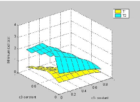
Figure 5 shows a more general analysis, in which the minimum of the tool cost function for all possibilities of
1
c ,c2and c3, with the restriction c1 c2 c3 1 is displayed. This analysis has revealed that the first tool is better than the second one for all combinations of the ciparameters. Thus, the output of the expert systems will be the first tool, while the cutting parameter can be obtained from the minimum of tool cost function for the selected tool for any values of c c c1, 2, 3.
Figure 3. Minimum tool cost function versus c1 varies, c3=0.025.
Figure 4. Minimum tool cost function versus c1 varies, c3=0.075.
[image:7.612.48.275.52.221.2]Figure 5. Minimum tool cost function versus c1,c2, c3 varies
The cutting parameters are obtained from section III.C, rules . For the example case, where c10.2,c20.6,c30.2,
1t 2t 0.5
c c , c1f c2f 0.5 and c1r0.8, c2r0.1,
3r 0.1
c the obtained cutting parameters are the spindle speed equal to 1000rpm, axial depth of cut equal to 1.4734mmand feed per tooth equal to 0.4944mm.
V. CONCLUSIONS
An efficient approach for mill cutter selection has been developed through an expert system. The expert system is instructed with the characteristics of the candidate tools, as well as with the stability margin and constraints of operations, such as, power availability and robust stability against chatter vibration. Furthermore, a tool cost model function, built from the expert system rules, is proposed to evaluate the possible performance of each candidate tool in milling process. This performance index is then used to select an appropriate tool. Adding the time and frequency designed cost functions, to the first one, a resultant cost function is obtained. It is used for the operation cutting parameters selection. A simulation example showing the behavior of the system is presented.
ACKNOWLEDGMENT
The Authors are very grateful to MCYT by its partial support through grant 2003-00164 and to the UPV/EHU through Project 9/UPV 00I06.I06-15263/2003.
REFERENCES
[1] S. Y. Liang, R. L. Hecker and R. G. Landers, “Machining Process Monitoring and Control: The State of the Art”, Journal of Manufacturing Science and Engineering, Vol.126, pp. 297-310, 2004. [2] S. V. Wong and A. M. S. Hamouda, “The development of an online
knowledge-based expert system for machinability data selection”,
Knowledge-Based Systems, Vol.16, pp. 215-219, 2003.
[3] M. C. Cakir, O. Irfan and K. Cavdar, “An expert system for die and mold making operations”, Robotics and Computer-Integrated Manufacturing, Vol.21, pp. 175-183, 2005.
[4] A. Vidal, M. Alberti, J.Ciurana and M. Casadesús, “A decision support system for optimizing the selection of parameters when planning milling operations”, International Journal of Machine Tools and Manufacture,
Vol.45, pp. 201-210, 2005.
[5] I. D. Carpenter and P. G. Maropoulos, “A flexible tool selection decision support system for milling operations”, Journal of Materials Processing Technology, Vol.107, pp. 143-152, 2000.
[6] Y. Altintas, Manufacturing Automation, Cambridge University Press, 2000
[7] L.Rubio and M. De la Sen, “Analytical procedure for chatter in milling”, Southeastem Europe, USA, Japan and European Community Workshop on Reseach and Education in Control and Signal Processing, June 14-16,
[image:7.612.47.276.249.417.2] [image:7.612.59.285.446.611.2]