University of Huddersfield Repository
Xu, Qian and Xu, Zhijie
A Hybrid Rendering Framework for the Realtime Manipulation of Volume and Surface Models
Original Citation
Xu, Qian and Xu, Zhijie (2009) A Hybrid Rendering Framework for the Realtime Manipulation of
Volume and Surface Models. In: Proceedings of the 15th International Conference on Automation
and Computing. Pacilantic International, pp. 160165. ISBN 9780955529344
This version is available at http://eprints.hud.ac.uk/id/eprint/7524/
The University Repository is a digital collection of the research output of the
University, available on Open Access. Copyright and Moral Rights for the items
on this site are retained by the individual author and/or other copyright owners.
Users may access full items free of charge; copies of full text items generally
can be reproduced, displayed or performed and given to third parties in any
format or medium for personal research or study, educational or notforprofit
purposes without prior permission or charge, provided:
•
The authors, title and full bibliographic details is credited in any copy;
•
A hyperlink and/or URL is included for the original metadata page; and
•
The content is not changed in any way.
For more information, including our policy and submission procedure, please
contact the Repository Team at: [email protected].
A Hybrid Rendering Framework for the Real-time
Manipulation of Volume and Surface Models
Qian Xu, Zhijie Xu
CGIV Research Group, University of Huddersfield Huddersfield, West Yorkshire, United Kingdom
Abstract—Stemmed from classical computer graphics research, volume visualization has been steadily growing into an important research field in the last 2 decades. This paper presents a hybrid rendering framework which integrates volume and surface models for real-time simulation. It focuses on improving the flexibility of the classic Scene Graph structure and the interactive rate of the Direct Volume Rendering (DVR)-based programming paradigm to enable the visualization of different type of models and their interactions. It is envisaged that this innovative functionality will open up a gate for the wider applications of volume rendering and visualization techniques on consumer-grade graphics platforms.
Keywords-volume model; surface model; hybrid rendering; volume visualization; virtual environment
I. INTRODUCTION
Over the last 2 decades, volume rendering and visualization technologies have attracted increasing attentions due to their potentials in revealing internal and hidden information from digitized computational geometric models for both academic research and industrial applications [1, 2]. Comparing with conventional 3D modeling and visualization techniques, volume rendering enables the direct access to the internal characteristics of a 3D object instead of merely focusing on the surface features alone inherited from a wireframe-based surface model. Its applications can extend from rapid prototyping in virtual manufacturing and medical imaging, to even astronomical and atmospheric simulations. With the ever increasing capacity of modern graphics hardware and the maturing methods for accelerating volume-based operations, real-time human interactions with complex volume models on consumer grade PC hardware have becoming a research hot-spot in the last decade.
As the demand increases for high-resolution results in visualization applications like medical imaging and design verifications, there also rises a need for improving the speed of online volume visualization and manipulation in a complex 3D scene. This trend has witnessed the ever growing data sizes to be processed by a rendering system in more tightly controlled time frame. In this research, a hybrid rendering framework has been devised and implemented for enhancing the accuracy and efficiency for various complex virtual environment (VE)-based applications. The project started from an investigation of volume and surface rendering mechanisms on PC platforms. A system structure and its corresponding
software framework were developed to accommodate the fundamentally different data structures involved and their rendering strategies under a unified process stream. A degree of success has been observed in a number of evaluative tests.
The paper is organized in the following order: Section II provides a brief review on various conventional rendering techniques. The scene graph of an innovative hybrid rendering framework is introduced in Section III. Section IV focuses on the results of various functional experiments carried out. Section V concludes the research with observations on the future works.
II. RESEARCH BACKGROUND
This section introduces the conventional surface and volume rendering approaches and their pros-and-cons.
A. Surface Modeling and Visualization
Surface models (sometime referred as solid models) provide visual representations of physical objects by “wrapping” up their underlying wireframe structures using specially calculated illumination or texturing information. The shape of a surface model is provided by edges which conjoin neighboring triangular (in rarer cases, quadrangular) polygons with their vertices (end points) defined in specified 3-Dimensional (3D) Cartesian coordinates systems [2]. Except simulation data-based surface models which are often generated from scientific computations, most surface model are “defined” by various geometric modeling tools such as Auto CAD, ProEngineer or the entertainment-oriented 3D Studio Max.
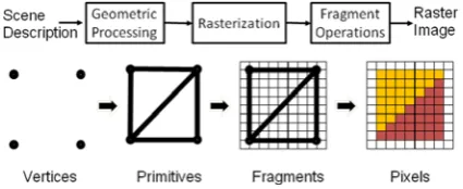
The process for visualizing a 3D surface model using a 2D displaying device has encompassed a wide area of research into computational geometry, computer graphics, displaying devices and so on over the last half-a-century. Figure 1 has given a grossly simplified diagram of the key processes involved.
As indicated in the diagram, the key stage to turn 3D entities (vertices) into 2D ones (fragments) is the so-called “geometric processing”, which if divided further will see the linear algebra-based transformation from the single model-based “Model Space” to the multiple model-based “World Space” [3]. The intermediate results will then be transferred into the “Camera/View Space” for interactive applications; and finally to the “Projection Space” for casting the objects’ silhouettes in the form of the short 2D lines – rasterized fragments – which are yet to be Proceedings of the 15th International Conference
processed further before turning into visible images. As shown in Figure 1, from fragments to pixels, various fragment-based operations will apply, namely a few, texture mapping, occlusion testing, stencil testing. Those operations are vital for the ultimate quality of the final display.
Figure 1. The surface model rendering pipeline
B. Volume Model and Rendering
Compared with surface model and its visualization approach, volume rendering has more complex tasks in hand. It involves the configuration of volume models and the selection of their processing tactics. There are several common volume model data formats such as “raw”, “img” and “hdr” for storing volume data. They are often obtained by specially designed industrial cameras, medical scanners, and even astronomical telescopes. Among those formats, the most popular one is the “raw”, which fulfill the same role as film negatives in traditional chemical photography.
The essential and basic element of volume models is the so-called voxel – the acronym for volume pixel. According to the choice of different optical models for filtering and integrating voxel information, a volume model can be rendered in various modes [4]. The basic theory of it is to calculate each voxel’s color and transparency impacts on the final image.
In Direct Volume Rendering (DVR), voxel is used to store the discrete volume data and arrange it in the so-called proxy geometries [3]. Depending on the type of the proxy geometries used, the volume model can either be presented in a single 3D block referred as view-aligned slices or being split up into three stacks of 2D slices named as object-aligned slices [3, 5, 6 and 7]. In contrast to DVR, Indirect Volume Rendering (IDVR) which is another branch of volume rendering strategies focuses on creating optical models by combining many iso-surfaces extracted from the volume data set to form the outer shape of the volume.
In DVR, after establishing the optical model, each voxel involved in calculation will be converted into color and translucent entities through classification. The theory of classification is to transform scalar voxel values into color indices through pre-defined look-up tables [8]. Although the original voxel scalar values might stand for density, temperature or intensity, they will all be converted into corresponding color and translucent values and to be integrated through specified process.
Different from the projection process in surface rendering, volume rendering utilizes the ray casting
technique (an image-order direct volume rendering algorithm) to “fill” the pixels on the image plane. Ray casting casts a configurable number of parallel rays across through the optical model in its model space [4] in one of two viable directions. One is the so-called back-to-front (from object space to image space) process; another follows the front-to-back order (from image space to object space). As indicated in Figure 3, each ray is casted into the model space and intersects with a group of voxels along the line. The corresponding optical properties obtained from the encountered voxels will be integrated along the ray to be projected to the image.
The pixel-based operation on image plane in volume rendering is similar to the surface pipeline, which will be discussed in detail in Section III. A simple illustration of the volume rendering pipeline is shown in Figure 3.
Figure 2. Ray casting (Forward-Mapping: from object space to image space)
Figure 3. Volume rendering pipeline
C. Current Difficulties
Although surface models are widely used in design and entertainment industries and are generally quick to render, they are inherently restricted for mainly visualization purposes due to lacking capacities in revealing internal and hidden information without any pre-definitions. For its modeling mechanism, surface models are mainly “defined” and rather difficult to be modified at application runtime, although Constructive Solid Modeling (CSG) techniques have provided limited Boolean-style operations at the model design time. In addition, surface model-based applications are often too relaxed on accuracy. The planar polygon-formed shapes are often rigid and incapable of representing organic objects. Therefore it is hard to maintain the accuracy of using surface model to simulate objects such as human brain and organs.
[image:3.595.313.531.262.400.2]volume model data sizes due to higher frequency of initial sampling for better accuracy and visual quality had further deteriorated the situation. For example, the size of a volume model is often at the scale of GB (giga-byte) for an ordinary daily item, which can quickly accumulate to TB (tera-byte), in the case of multi-object 3D scenes with complex organic.
In this project, the main research objectives can be divided into two tiers. The first tier is to integrate surface and volume visualizations into a unified rendering framework to facilitate hybrid virtual environment operations. The second tier is to accelerate the rendering on consumer-grade PC hardware by introducing data and even task parallelism. This paper will focus on works carried out to tackle the first task. Progress concerning task 2 has been published in separate articles [9, 10].
III. HYBRID RENDERING FRAMEWORK DESIGN
A. Hybrid Scene Graph Design
[image:4.595.313.534.75.227.2]As Discussed in Section II, volume and surface rendering approaches are quite distinctive from each other; however, both the final results are turned into color values in the frame buffer which exposes the potentials for their integration. Based on this, an innovative scene graph structure is proposed which can handle both surface and volume models in a unified 3D space with their depth information correctly sorted for occlusion calculation as illustrated in Figure 4.
Figure 4. Volume and surface models
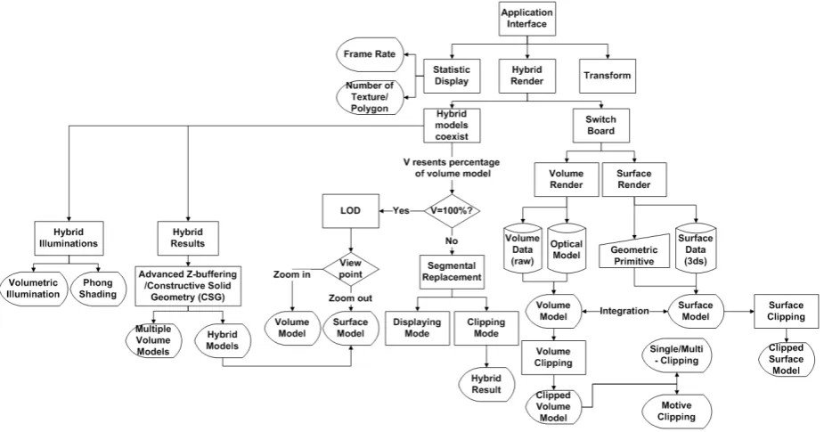
An intelligent “switch” mechanism is the key to the hybrid rendering framework design. By checking indicative parameter values and setting up thresholds carefully, appropriate rendering strategies and techniques can be applied according to the specific application requirements at runtime. For example, a virtual Flexible Manufacturing Cell (FMS) might consist of an assembling robot and a CNC station. The object of interest in this virtual environment (VE) for process planning is the workpiece. In this case, it can be exhibited in the volume style for operation simulation. The robot in this application can be simply represented by a surface model to demonstrate its movement range. A prototype system has been built in this project for deploying and testing the hybrid rendering framework design. The framework of the system is illustrated in Figure 5.
Figure 5. The framework of hybrid rendering application
B. Framework Implementation
[image:4.595.72.535.454.696.2]a number of new node types, such as volume LOD, Segmental Replacer, Multi-Volume, and Clipping node to accommodate and utilize volume models and their distinctive features.
1) Level-of-Detail Node
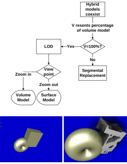
[image:5.595.314.537.73.424.2]The Level-of-Detail (LOD) node aims at switching in between surface models and their corresponding volume ones for controlling the visualization workload. Benefiting from the idea of the traditional polygonal LOD node in large-scale and complex 3D scene management [11], a volume LOD is switching mechanism that provides object-level optimization in between volume and surface models. The key of this effort is to thresholding the special “indicators” for replacement, i.e. based on the distance between the viewpoint and the object, or based on the interaction type deployed in the simulation. Figure 6 shows the LOD conceptual process flow.
Figure 6. Volume Level-of-Detail (LOD) node.
2) Segmental Replacer Node
[image:5.595.68.280.273.546.2]Comparing with the LOD, using a surface model to partially replace a volume one is another visualization strategy explored in this framework. As shown in Figure 7, about a quarter of an engine surface box model is of the volume type to exhibit internal information of the model. The volumetric section is obtained by clipping the Engine model along the vertical and horizontal planes and to generate quadruple sub-parts of the original model. The darker area is the surface counterparts for filling the original volume space in the VE. The size and proportion of these two parts can be customized for different applications in this framework design. In this design, the rendering of an entire volume model can be avoided for facilitating real-time simulations.
Figure 7. The segmental replacer node and its application.
3) Multi-Volume Node
In addition to being integrated into a surface model-dominant 3D scene, volume models sometimes coexist with each other for certain applications. Figure 8 shows a snapshot of a multi-volume node at runtime with the two clones of a volume model sorted by distances from the viewpoint.
Figure 8. A multiple volume node application.
4) Volume Clipping Node
Volume clipping provides effective assistance in understanding 3D volumes through revealing the internal
Hybrid models coexist
V=100%? LOD
V resents percentage of volume model
Yes
Segmental Replacement
No
View point
Zoom out Zoom in
Volume Model
Surface Model
Hybrid models coexist
V=100%? LOD
V resents percentage of volume model
Yes
Segmental Replacement
No
Volume Clipping
Surface Clipping
Hybrid Result
Clipped Volume Model
Clipped Surface Model Single/Multi
- Clipping
Clipping Mode
[image:5.595.313.530.541.693.2]structures of a volume model. It is considered a complement to the specification of the transfer functions [5]. As shown in Figure 6, the voxel inside the clip geometry has been initialized to 0 with remaining voxels set as 1 to set the unwanted part to be transparent. In volume clipping literatures, unwanted part is often called the clipping object and the remainder is named as the clipped object.
Figure 9. Volume clipping graph.
Figure 10. A Clipped engine box.
As a part of the framework, the clipping node can be modified and transformed readily. There are three clipping modes: mode 1 means the part inside the clipping geometry is the clipped object; mode 2 means the part outside the clipping geometry is the clipped object; and mode 3 initializes the clipped volume model and attaches it to the clipping geometry. However, multi-volume clipping cannot be realized directly by issuing the same clipping operation twice. The solution is through creating a clipping-geometry-list to arrange these different clipping geometries. The multiple clipping method has also been utilized in the design segmental replacer node.
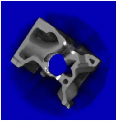
As shown in Figure 11, the Engine box was clipped in the 2nd clipping mode explained above and the clipping geometries consist of a cylinder and a box shape.
Figure 11. Multiple clipping image.
C. User Interface Design
As an important part of the system, the user interface requires an intuitive and interactive display mode that can enhance users’ visual awareness when carrying out an application task [12]. Some HCI researchers reported that intuitive data exploration can be treated as an extra dimension of information [13, 14 and 15]. Many poorly designed applications interfaces suffer from lost tracks when changes being applied to the settings of one or more of the flow parameters in the system. A multiple viewport user interface design has been adopted in this project which is capable of showing the entire 3D scene, any
highlighted models, and corresponding rendering
information in 3 separate viewports. By interactively (drag-and-drop style) changing the rendering settings in the coding viewport, the changes on the model and scene can be automatically updated at real-time.
IV. PROTOTYPE IMPLEMENTATION
This hybrid rendering system devised in this research has been implemented using OpenGL and OpenSG APIs in a VC++ programming environment. The host PC is an Intel Core2 2.40GHz CPU with 2G RAM.
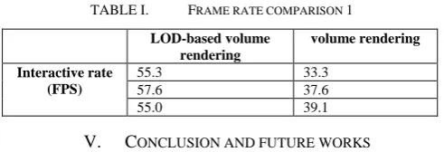
As shown in Figure 8 and Figure 11, multi-volume coexistence and segmental replacer are the two key innovative elements in the system. In the meantime, the LOD and the clipping nodes are the “cheaper” solutions for some visualization-oriented (non-simulation-intensive) operations. Tests have been carried out on the performance of the LOD node. The result is shown in Table I, when the actual operations can be simplified as the pseudocode below:
Volume Clipping Volume Model
Clipped Volume Model
Single/Multi - Clipping
[image:6.595.63.282.233.603.2]As clearly shown in Table I, the result of the frame rate comparison proves that using surface models to replace volume ones at a carefully chosen threshold can effectively improve the interactive rate without losing too much visual qualities. Experiments on other devised modes and more complex 3D VE will be discussed in separate articles.
TABLE I. FRAME RATE COMPARISON 1 LOD-based volume
rendering
volume rendering
Interactive rate (FPS)
55.3 33.3
57.6 37.6
55.0 39.1
V. CONCLUSION AND FUTURE WORKS
The LOD, segmental replacer, multi-volume and clipping nodes are the essential functional modules of the devised hybrid rendering framework that had been implemented and tested in this project. The evaluation of the framework and tests on the prototype detailed in Section III and Section IV have demonstrated the feasibility and flexibility of the design. Further improvements and tests on accelerating the systems using hardware-driven data parallelism will be carried out in the next phase of this project.
In addition, there are some derived problems from classical volume rendering, e.g. the problem of multi-model clipping will seriously affect the interactive rate at runtime if not being used properly. Another prominent problem is the unavailability of volume-based depth buffering. The final rendered frame with multiple volume models cannot always show the correct occlusions like the wireframe ones. Problems also rise in this framework when applying certain illumination terms for complex VE applications. These problems will be addressed in the future works of the project.
ACKNOWLEDGMENT
I would firstly like to thank my first supervisor Dr Zhijie Xu for his great supervision and guidance during this research. I am deeply impressed on his erudition in knowledge and attitude in science which promote me to
keep on going. I would like to show my grateful appreciation to Mr. Jing Wang, Mr. Yang Su for their great helps to me.
REFERENCES
[1] S. Zhang, C. Demiralp, D. F. Keefe, P. J. Basser, and E. A. Chiocca, “An Immersive Virtual Environment for DT-MRI Volume Visualizations: A Case Study,” 2001.
[2] F. Romeiro, L. Velho, and De. F. l. Henrique, “Hardware-assisted Rendering of CSG Models,” In SIBGRAPI, 2006
[3] S. Sar-Dessai, and M. Botsch, “The lecture notes on “Computer Graphics I" held by Prof. Dr. Leif Kobbelt at RWTH Aachen,” In summer term 2003.
[4] S. Stegmaier, M. Strengert, T. Klein, and T. Ertl, “A Simple and Flexible Volume Rendering Framework for Graphics-Hardware-based Raycasting,” In Proceedings of Volume Graphics 2005, Stony Brook, New York, USA, 2005, pp.187-195.
[5] D. Weiskopf, K. Engel, and T. Ertl, “Interactive Clipping Techniques for Texture-Based Volume Visualization and Volume Shading,” In IEEE Transactions on Visualization and Computer Graphics, 2003.
[6] M. Weiler, R. Westermann, C. Hansen, K. Zimmerman, and T. Ertl, “Level-Of-Detail Volume Rendering via 3D Textures,” In Proc. IEEE Volume Visualization and Graphics Sympsium 2000.
[7] K. Engel, M. Kraus, and T. Ertl, “High-Quality Pre-Integrated Volume Rendering Using Hardware-Accelerated Pixel Shading,” In Proc. Eurographics/SIGGRAPH Workshop on Graphics Hardware, 2001.
[8] K. Engel, M. Hadwiger, J. M. Kniss, A. E. Lefohn, C. R. Salama, and D. Weiskopf, “Course Notes 28: Real-Time Volume Graphics,” In SIGGRAPH 2004.
[9] Y.Su, Z.Xu, X.Jiang, and P.Jonathan, “Discrete Wavelet Transform on Consumer-level Graphics Processing Unit.” In: Processing of Computing and Engineering Annual Researchers’ Conference 2008: CEARC’ 08, University of Huddersfield, Huddersfield, pp.40-47.
[10] Y.Su, Z.Xu, and X.Jiang, “GPGPU-based Gaussian Filtering for Surface Metrological Data Processing,” In: Information Visualization, 2008 IV apos; 08. 12th International Conference. Information Visualization, 2008. IV apos;08. 12th international conference, pp.94-99.
[11] J. H. Clark, “Hierarchical Geometric Models for Visible Surface Algorithms. Communications of ACM,” Vol.19, No.10, 1976, pp. 547-554.
[12] A. Cooper, and R. Reimann, “About Face 2.0: The Essentials of Interaction Design,” Wiley, New York, 2003.
[13] M. Tory, S. Potts, and T. Moller, “A Parallel Coordinates Style Interface for Exploratory Volume Visualization,” In IEEE Transactions on Visualization and Computer Graphics, vol.11, no.1, 2005 pp.71-80.
[14] T. J. Jankun-Kelly, and K. L. Ma, “A Spreadsheet Interface for Volume Visualization,” In Proceedings of IEEE Visualization 2000 Conference, 2000.
[15] K. L. Ma, “Image Graph: A Novel Approach to Visual Data Exploration,” In Proceedings of IEEE Visualization ’99 Conference, 1999, pp.81-88.
Per-frame Operations:
Loading model
Thresholding model types
Loading corresponding rendering core
Interaction transformations