University of Huddersfield Repository
Li, Feng, Longstaff, Andrew P., Fletcher, Simon and Myers, Alan
Integrated TactileOptical Coordinate System for the Reverse Engineering of Complex Geometry
Original Citation
Li, Feng, Longstaff, Andrew P., Fletcher, Simon and Myers, Alan (2013) Integrated TactileOptical
Coordinate System for the Reverse Engineering of Complex Geometry. In: Proceedings of the 37th
International MATADOR Conference. Springer, pp. 4144. ISBN 9781447144793
This version is available at http://eprints.hud.ac.uk/id/eprint/14509/
The University Repository is a digital collection of the research output of the
University, available on Open Access. Copyright and Moral Rights for the items
on this site are retained by the individual author and/or other copyright owners.
Users may access full items free of charge; copies of full text items generally
can be reproduced, displayed or performed and given to third parties in any
format or medium for personal research or study, educational or notforprofit
purposes without prior permission or charge, provided:
•
The authors, title and full bibliographic details is credited in any copy;
•
A hyperlink and/or URL is included for the original metadata page; and
•
The content is not changed in any way.
For more information, including our policy and submission procedure, please
contact the Repository Team at: [email protected].
Integrated Tactile-Optical Coordinate System for the Reverse Engineering
of Complex Geometry
F Li, AP Longstaff, S Fletcher, A Myers
Centre for Precision Technologies, School of Computing and Engineering, University of Huddersfield Queensgate, Huddersfield, HD1 3DH, UK
Abstract. To meet the requirement of both high speed and high accuracy 3D measurement for reverse engineering of artefacts, an integrated contact–optical coordinate measuring system is proposed in this paper. It combines the accuracy of contact measurement using a co-ordinate measuring machine (CMM) and the efficiency of full field of structured light optical scanning methods using a projector and two CCD cameras. A planar target printed with square patterns is adopted to calibrate the projector and cameras while three calibration balls are used to unify two coordinate systems. The measurement process starts from cameras around the volume to capture its entire surface, then the CMM’s probe is used to re-measure areas of the object that have not been adequately scanned. Finally the combined data from both systems is unified into the same coordinate system. In this paper the hybrid measurement of a guitar body proves the feasibility of this method.
Keywords: Integrated system, Structured light measuring, CMM, 3D measurement, Data fusion
1 Introduction
In recent years, extensive attention has been given to different methodologies of reverse engineering (RE) aimed at developing more effective measurement methods which provide both high speed and high accuracy. The existing CMM methods are widely used for industrial dimensional metrology, but the digitisation process is very time-consuming for the acquisition of the first set of points on complex, freeform surfaces. An alternative approach is represented by non-contact digitisation of surfaces based on optical techniques, such as time-of-flight lasers [1], laser scanning [2, 3], stereovision [4] and structured light [5]. These optical instruments can efficiently capture dense point clouds in terms of speed and reduces the human labour required. However it is usually difficult for the optical sensors to digitize the non-surface objects, such as slots or holes, due to occlusions and obscuration of these artefacts.
The reduction of the lead time in RE, and the increased requirements in term of flexibility as well as
accuracy have resulted in a great deal of research effort aimed at developing and implementing combined systems for the RE based on cooperative integration of in homogeneous sensors such as mechanical probes and optical systems[6-9]. Particular features of a workpiece can be measured with the most suitable sensor, and these measurements with low uncertainty can be used to correct data from other sensors which exhibit systematic errors but have a wider field of view or application range.
2 F. Li, A.P.Longstaff, S.Fletcher and A. Myers
2 System Configuration
2.1 Elements of The Integrated System
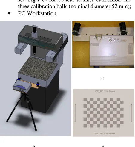
The integrated system (see Fig. 1 a) is designed and manufactured with the following components:
• Two CCD cameras: IDS UI-1485LE-M-GL, the CCD array resolution is 2560(H) x 1920(V), the dimension of a pixel on CCD array is 2.2um × 2.2um (see Fig. 1 b);
• Lens: Fujinon HF12,5SA-1/1,4 5 Megapixel C-Mount Lens, the focal length is 12.5 mm;
• Projector: Panasonic PT-LB60NTEA projector with 1,024 x 768 pixels;
• Co-ordinate measuring machine (CMM): Renishaw cyclone;
• FlexScan3D PRO 3D scanning software;
• Calibration board (12W × 9H × 15 mm Squares,
see Fig.1 c) for optical scanner calibration and three calibration balls (nominal diameter 52 mm);
• PC Workstation.
a
b
c
Fig 1. Elements of the integrated system a. the integrated system; b. cameras and projector ; c. calibration board
2.2 The Principle of Optical System
The optical system is based on the structured light measurement technique [10-14] with digital sinusoidal fringe and Gray code projection and consists of a digital projector and two CCD cameras that provide redundancy to reduce the effect of obstructions and improve accuracy. The measurement process is performed in three steps: Generation of stripe patterns, phase measurement (based
on the analysis of deformed stripe patterns) and calibration of the phase values in each pixel of the camera to the real-world (x, y, z) Cartesian coordinates.
3 Measurement Process of The Integrated System
3.1 Calibration of The Optical System
There are many studies of modelling and calibration of CCD cameras. Camera calibration in the context of 3D optical measurements is the process of determining the transformation from 2D CCD image to 3D world coordinate system. The parameters to be calibrated include intrinsic parameters and extrinsic parameters. The intrinsic parameters involve: (1) effective focal length— the distance between the projection centre and the image plane, (2) principle point—the intersection of the optical axis and the image plane, (3) lens distortion and (4) aspect ratio—the length–width ratio of each pixel. The extrinsic parameters involve the transformations between the world coordinate system, the camera coordinate system and the image coordinate system. Extrinsic parameters are needed to transform object coordinates to a camera-centred coordinate system. In many cases the overall performance of a machine vision system strongly depends on the accuracy of the camera calibration procedure [15-19].
To solve all of the intrinsic and extrinsic parameters simultaneously, at least six non-coplanar points in the world coordinate system and their correspondences on the image are required. Zhang [20] proposed a flexible technique for camera calibration by viewing a plane from different unknown orientations. Accurate calibration points can be easily obtained using this method.
3.2 Data Fusion of Integrated System
Multisensor data fusion in dimensional metrology can be defined as the process of combining data from several information sources (sensors) into a common representational format in order that the metrological evaluation can benefit from all available sensor information and data [9].The optical scanner and the CMM work in their own separate coordinate systems. If the integrated system is to produce useable results, these two coordinate systems have to be unified.
[image:3.595.69.295.327.574.2]a three-point alignment coordinate transformation method can be used to deal with data fusion.
Since the error of each measuring reference point can be seen as equal weight value, the data fusion errors can be seen as average distributed errors [21]. It is usually very difficult to obtain the same reference point from two different sensors (CCD cameras and CMM in this case) because of different measurement principles and methods of two systems as well as different point cloud density. If we take a reference feature point as the calibration reference point every time, the possibility of occurrence of system error, human errors and accidental errors will increase greatly. Because three points can establish a coordinate, we can calculate the centroid of a standard calibration ball and then use the sphere centre coordinate as the datum reference point coordinate to achieve data fusion and reduce fusion errors.
The data fusion of 3D measurement data from different systems will be achieved through the alignment of three datum sphere centre points. In fact, the data fusion problem is, therefore, converted to a coordinate transformation problem. The transformation is determined by comparing the calculated coordinates of the centres of the calibration balls obtained in measurement conducted by the optical system [8]:
T
W
R
W
s
CMM
=
⋅
+
(1)where
W
CMM is the points’ coordinates in CMMalignment;
R
is the rotation matrix; sW
is the point’scoordinates in optical alignment; and
T
is the translationvector.
Specific methods are as follows:
1. Calibrate the optical system (section 3.1); 2. Use CMM to measure the surfaces of three
standard balls;
3. Use structured light scanner to measure the surfaces of the same standard balls;
4. Use optical scanner and CMM measure the workpieces separately;
5. Calculate the sphere centre coordinates measured in two systems and use the sphere centre as reference points to achieve data fusion.
This measuring ball operation has to be performed prior to any measurement, after the calibration of the optical system. It is carried out only once before a series of measurements. Change of configuration of any of systems results in the need of repeating the unification process. The result of this process is a transformation matrix, which modifies (rotates and translates) the point’s coordinates from the optical scanners’ relative coordinate system to the absolute system of the CMM.
4 Experimental Results
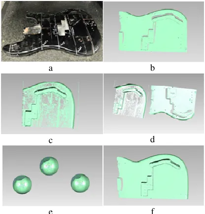
After building the integrated system, an electrical guitar body (see Fig.2a) has been used to demonstrate the feasibility of the proposed method. The surface of guitar body includes a freeform surface and a pick-up slot which is difficult to measure for an optical scanner because of occlusions and obscuration of artefacts. Therefore we can use optical scanner to capture the freeform surface 3D data of guitar body then digitize the pick-up slot surface by using the CMM.
a b
c d
[image:4.595.315.523.231.448.2]e f
Fig. 2. Guitar body points cloud data coordinate system unification a. optical scanner measurement; b. data measured by optical scanner; c.
data measured by CMM; d. data measured by two systems; e. calculation of ball sphere centre; f. data fusion of two systems.
Specific steps are as follows:
1. Calibrate the optical scanner by using a calibration board, then use both CMM and optical scanner to measure three calibration balls mounted on the CMM granite bed.
CMM-4 F. Li, A.P.Longstaff, S.Fletcher and A. Myers
contact digitisation of one guitar surface need more than 8 hours, while the hybrid system can finish the measurement within one hour. The point cloud data obtained in both systems as shown in Fig.2d.
3. Calculate the sphere centre coordinates calibration balls measured in two systems (see Fig.2 e).
4. Use the sphere centre coordinates to unify the two coordinate systems, the unified guitar point clouds data as shown in Fig.2 f.
5 Conclusions and Discussions
To meet the requirement of measuring complex geometry of workpieces with high accuracy and speed, a full field of integrated scanning system, which mainly consists of a CMM, two CCD cameras and a DLP based standard projector, has been developed in this paper. The unification of contact and non-contact systems are fulfilled by using three calibration balls mounted on a CMM granite bed. The hybrid measurement of guitar body showed this approach is simple, convenient, efficient and reliable.
However, in this paper we do not verify the accuracy of the integrated system. No visual separation between the data sets from different measuring systems indicates a fit accuracy within 0.5mm, proving the feasibility of this approach. Theoretically, the integrated system accuracy and resolution depend on both separate systems, but should be biased towards the contact method, and can be improved by improving the specifications of hardware, including choosing a higher accuracy CMM, choosing more precise calibration balls and a higher resolution projector which can provide sharper stripe. Reducing the measuring range can also improve the system accuracy.
Further research will include more extensive experiments to test the accuracy of the integrated system and more sophisticated design of the algorithm to reduce the manual intervention.
6 Acknowledgements
The authors gratefully acknowledge the UK’s Engineering and Physical Sciences Research Council (EPSRC) funding, of the Centre for Advanced Metrology under its innovative manufacturing program.
7 References
[1] A. Ullrich, N. Studnicka, J. Riegl et al., Long-range high-performance time-of-flight-based 3d imaging sensors, in: 3D Data Processing Visualization and Transmission, Padova, Italy 2002, pp. 852–855.
[2] K.-C. Fan, A non-contact automatic measurement for free-form surface profiles, Computer Integrated Manufacturing System 10 (1997) 277–285.
[3] G. Wang, B. Zheng, X. Li, Z. Houkes, Modeling and calibration of the laser beam scanning triangulation measurement system, Robotics and Autonomous Systems 40 (2002) 267–277.
[4] D. Gorpas, K. Politopoulos, D. Yova, A binocular machine vision system for three-dimensional surface measurement of small objects, Computerized Medical Imaging and Graphics 31 (8) (2007) 625–637.
[5] J. Salvi, J. Page‘s, J. Batlle, Pattern codification strategies in structured light systems, Pattern Recognition 37 (4) (2004) 827–849.
[6] Carbone, V., et al., Combination of a Vision System and a Coordinate Measuring Machine for the Reverse Engineering of Freeform Surfaces. The International Journal of Advanced Manufacturing Technology, 2001. 17(4): p. 263-271. [7] Chan, V.H., C. Bradley, and G.W. Vickers, A multi-sensor
approach to automating co-ordinate measuring machine-based reverse engineering. Computers in Industry, 2001. 44(2): p. 105-115.
[8] Sladek, J., et al., The hybrid contact-optical coordinate measuring system. Measurement, 2011. 44(3): p. 503-510. [9] Weckenmann, A., et al., Multisensor data fusion in
dimensional metrology. CIRP Annals - Manufacturing Technology, 2009. 58(2): p. 701-721.
[10] V. Srinivasan, H. C. Liu, and M. Halioua, Automated phase-measuring profilometry of 3-D diffuse objects. Applied Optics, Vol. 23, 1984, pp. 3105-3108.
[11] Halioua, M. and H.-C. Liu, Optical three-dimensional sensing by phase measuring profilometry. Optics and Lasers in Engineering, 1989. 11(3): p. 185-215.
[12] Wei Pan, Yi Zhao, Xueyu Ruan, Aplication of phase shifting method in projection grating measurement, Journal of Applied Optics. 2003. 24( 4): pp.46-49.
[13] Peisen S. Huang and Song Zhang, Fast three-step phase-shifting algorithm, Applied Optics, 2006. Vol. 45, pp. 5086-5091.
[14] Song Zhang and Shing-Tung Yau, High-speed three-dimensional shape measurement system using a modified two-plus-one phase-shifting algorithm, Optical Engineering. 2007, 46(11), 113603
[15] E.M. Mikhail, J.S. Bethel, J.C. McGlone, Introduction to Modern Photogrammetry, John Wiley and Sons, Inc., 2001. [16] O. Faugeras, Three-dimensional Computer Vision: A
Geometric Viewpoint, The MIT Press, Fourth Printing, 2001. [17] Micheals RJ, Boult TE. On the Robustness of Absolute
Orientation. In: Proceeding of the International Association for Science and Technology Development (IASTED) Conference on Robotics and Automation. 2000.
[18] Sheng-Wen, S., H. Yi-Ping, and L. Wei-Song. Accuracy analysis on the estimation of camera parameters for active vision systems. in Pattern Recognition, 1996., Proceedings of the 13th International Conference on. 1996.
[19] Sagawa, R. and Y. Yagi. Accurate calibration of intrinsic camera parameters by observing parallel light pairs. in Robotics and Automation, 2008. ICRA 2008. IEEE International Conference on. 2008.
[20] Z. Zhang, A flexible new technique for camera calibration, IEEE Transactions on Pattern Analysis and Machine Intelligence 22 (2000)1330–1334.