2016 3rd International Conference on Information and Communication Technology for Education (ICTE 2016) ISBN: 978-1-60595-372-4
1 INSTRUCTIONS
With the development of oil industry, oil and gas resources stored in shallow formations are depleted, so it becomes more and more urgent to drill oil and gas resource in these places where have complex geological conditions and hard formations. But how to raise drilling velocity in hard formations has always been a difficult problem all over the world. Through some tests, it has been found that particle impact drilling is an efficient way to raise the drilling velocity. Particle impact drilling is the common drilling fluid with steel particles. When the drill rotating progressively to break rock, the particles in the drilling fluid will break and etch hard rock. Some companies such as the Particle Drilling Technologies, Inc. have done field test based on several years of study. In recent years, some Chinese universities such as Beijing University of Chemical Technology, China University of Petroleum and Southwest Petroleum University, have begun to do related study and experiment and have made achievements successfully, promoting the development of particle impact drilling technology. Most studies of particle impact drilling technology prefer to studying on rock breaking mechanism and parameters optimization instead of the performance of flow field in different parameters. So it is worthy to do numerical simulations of drilling in different conditions by using Computational Fluid Dynamics and do more studies on the performance of the drilling flow fluid in different main parameters, including particle diameter, particles volume fraction, nozzle pressure and confining pressure,
which can offer reference materials and theories for subsequent study.
2 PARTICLE DRILL MODEL
As for the drilling bit, choose 8.5 inches deep conical bit, its diameter is 215.9mm, the total length of the drill is 300mm, and the full diameter of thread is 114.3mm. As for outside wall of the bit, choose the CP1412 type bit gauge, the tooth depth is about 12mm.The gap between the bit model and the wall is set as 12mm.
3 CALCULATION MODEL
3.1 Discrete model
The particles volume fraction in the whole drilling fluid is less than 5% and the particles do not react with the fluid, so it is appropriate to choose discrete model to study the influence on the performance of the bottom hole flow field and the interaction between continuous phase and discrete phase. Record the particle trajectory to analyze the particles distribution law.
The following is the motive equation of the particles:
(
)
(
)
Xp p x p D p
F g
u u F dt du
+ − +
− =
ρ ρ ρ
(1)
Where u = fluid velocity; ρp= particle destiny; dp
= particle diameter; µ = fluid dynamic viscosity; up
= particle velocity; ρ = fluid destiny; FD= dag force;
Numerical Simulation on Flow Field of Particle Impact Drilling in
Different Drilling Parameters
Tingjun Yan, Jinghao Li, Linna Zhao
Beijing University of Chemical Technology, Chaoyang, Beijing, P.R. China, 100029
Tingjie Yan
Drilling Training Center, Shenli Petroleum Administration, Dongying, P.R. China, 257964
and FX = other forces, such as virtual mass force, rotary force and etc.
The particles trajectory and the transmission of the quality is calculated by integral in discrete tiny changing time steps. The following is the general equation:
p
u dt dx
= (2)
Through the momentum transformation equation and the mass transformation equation, the force is transformed between the fluid and particles. The following is the momentum transformation equation:
(
u u)
F m t dR C
F P other p
P P e D ∆ + −
=
∑
2 .24 18
ρ βµ
(3)
The following is the mass transformation equation: 0 , 0 , p p p m m m
M = ∆ (4)
Where dp = particle diameter; m .
p = mass flow rate of the particles; ∆mp = quality change of the particle between two steps; mp,0 = initial quality of the particle; m
.
p,0 = initial mass flow rate of the particles; and Re = relative Reynolds number.
3.2 Boundary conditions
The particle-containing drilling fluid is an incompressible fluid. According to the PDTI’s study on the particle injection system, only if the particle injection velocity is above 150m/s, can have ideal result. So following is the set parameters:
Entrance conditions: Set entrance velocity as 150m/s and the direction of velocity is perpendicular to the entrance direction of the muzzle;
Exit conditions: After injecting the drilling fluid and impacting the rock, the drilling fluid flow through the junk slot and flow out through the gap between the wellbore and the drill pipe.
4 FINITE ELEMENT RESULTS ANALYSIS
4.1 Influence on the bottom hole flow field in different particle diameters
The muzzle will be blocked if the particles diameter is too large to get through the muzzle which will hamper the progress of the drilling. And the particle diameter should be large enough to break rock, so it is necessary to set particles diameter of 1mm ~ 4mm in the simulation.
The figure 1 is the simulation results of the surface pressure in different particle diameters. In the figure 1, it can be seen that the larger the
diameter is, the smaller the peak pressure is. With the decrease of the pressure, the effect of the particle impacting rock becomes weak. So the particle diameter should not be set too large. And in the same time, the particles with a small diameter has a weak effect on the surface pressure distribution. In conclusion, it is appropriate to set the particle diameter of 2mm ~ 3mm.
Figure 1. Surface pressure comparison picture in different particles diameters.
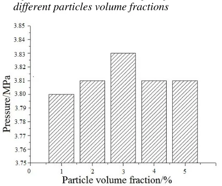
4.2 Influence on the bottom hole flow fluid in different particles volume fractions
Figure 2. Surface pressure comparison picture in different particles volume fraction.
The particles volume fraction in the drilling fluid is less than 5%. So in the simulation, set the particles volume fraction of 1% ~ 5%.
[image:2.612.324.544.132.321.2] [image:2.612.322.549.363.553.2]volume fraction should be set as 3% or a little bigger than 3%.
(a) 1%
(b) 3%
(c) 4%
(d) 5%
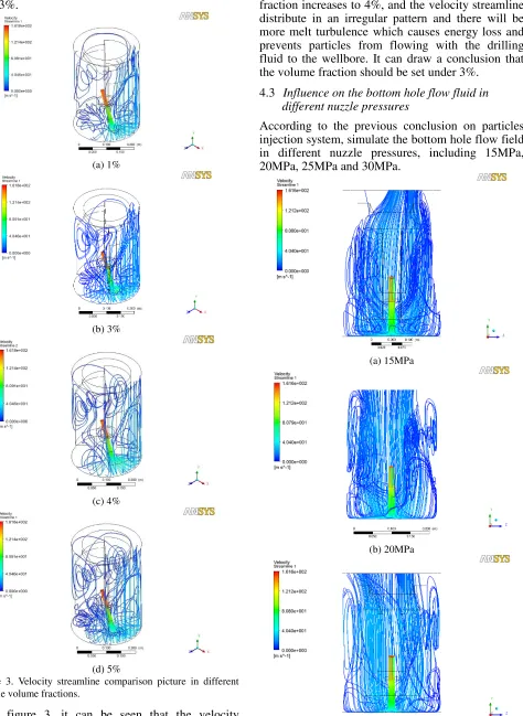
Figure 3. Velocity streamline comparison picture in different particle volume fractions.
In figure 3, it can be seen that the velocity streamlines distribute in a regular pattern when the particles volume fraction is between 1% and 3%, and almost all the particles flow towards the exit directly instead of flowing back. There are more vortices in
the bottom and the junk slot when the volume fraction increases to 4%, and the velocity streamline distribute in an irregular pattern and there will be more melt turbulence which causes energy loss and prevents particles from flowing with the drilling fluid to the wellbore. It can draw a conclusion that the volume fraction should be set under 3%.
4.3 Influence on the bottom hole flow fluid in different nuzzle pressures
According to the previous conclusion on particles injection system, simulate the bottom hole flow field in different nuzzle pressures, including 15MPa, 20MPa, 25MPa and 30MPa.
(a) 15MPa
(b) 20MPa
[image:3.612.80.554.46.695.2](d) 30MPa
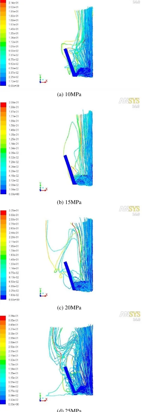
Figure 4. Velocity streamlines comparison picture in different pumping pressures.
In figure 4, it can be seen that the nuzzle pressure has a prominent effect on melt turbulence. From the picture (a), (b) and (c), it can be obviously seen that there is much melt turbulence in junk slot which damage the drill and wellbore wall and cause large vortices and much energy loss. From the picture (d), it can be seen that the velocity streamlines distribute in a regular pattern and there are less vortices and melt turbulence. so it is better to set the nuzzle pressure as 30MPa which has a good influence in the distribution of the flow fluid.
4.4 Influence on the bottom hole flow fluid in different confining pressures
The value of the confining pressure is approximately equal to the hydrostatic pressure which is the exit pressure when the oil well is submerged. The confining pressure changes with the formation depth. So set the confining pressure as 10MPa, 15MPa, 20MPa and 25MPa.
In the figure 5, it can be seen that the larger the confining pressure is, the longer the particles residence time in the bottom hole flow field is. The residence time is the longest when the pressure reaches to 25MPa. The particles will damage the drill when the pressure reaches to 10MPa. When the pressure is 15MPa, the particles will flow to wellbore directly. The backflow begins to take place when the pressure reach to 20MPa. And there is serious backflow phenomenon which has a bad effect on ejecting particles. The possibility of the particles depositing will increase greatly. So it is appropriate to set the confining pressure of 15MPa ~ 20MPa.
(a) 10MPa
(b) 15MPa
(c) 20MPa
[image:4.612.65.241.39.202.2](d) 25MPa
[image:4.612.320.556.43.725.2]5 CONCLUSION
According to above study, influence of particle parameters on performance of bottom hole flow field are simulated and leading to the following results:
With the increase of the particles diameter, the surface pressure decreases which means that the effect on breaking rock becomes weak and causes more energy loss. It can be concluded that a small diameter benefits of drilling. In the same time, the diameter should be big enough to break rock. After considering all the situations, it is appropriate to set the particle diameter as 3mm.
With the increase of the particles volume fraction, the peak surface pressure increase first and then decrease. The peak surface pressure is the largest when the volume fraction is 3%. From the perspective of energy, the energy consumption is nearly invariable in different volume fractions. So it is appropriate to set the particles volume pressure as 3%.
It can be seen from the particles trajectories that the particles trajectories have a trend to concentrate with the increase of the nuzzle pressure. From the perspective of the particles residence time, when the pressure reaches to 20MPa, the area that the particles concentrate is larger, which can increase the sheet flood area and the capacity of jet flow and breaking rock.
The particles residence time on the bottom hole flow field increase with the confining pressure increasing, which has disadvantages on the particles ejecting. From the perspective of the particles mass consistence distribution, it is appropriate to set the confining pressure as 15MPa for a smaller particles concentrating area and a smaller concentration.
REFERENCES
[1]Tibbitt G A, Galloway G. Particle Drilling Alters Standard Rock-Cutting Approach[J]. World Oil, June 2008
[2]F. S. Ren, R. X. Ma, X. Z. Cheng, B. J. Wang. Research Progress and Key Problem of Particle Impact Drilling Technology[J]. Oil Field Equipment[J]. Vols. 43 Iss.7, pp. 20-25, 2014 (in Chinese)
[3]Nina M. Rach. Particle-Impact Drilling Blasts Away Hard Rock[J]. Oil & Gas Journal, Vols. 2, pp. 43-45, 2007 [4]H. Y. Sun, Y. Zhang, B. B. Wang, Numerical Simulation of
Liquid-Solid Two-Phase Flow Reflux in Particle Impact Drilling System, Advanced Materials Research[J]. Vol. 402, pp. 824-827, 2012 (in Chinese)
[5]Particle Drilling Technologies, Inc. Impact excavation system and method with suspension flow control: US, 7258176B2[P]. 2008-03-18
[6]L. N. Xu. Study on Experiment of Bit Nozzle of Particle Impact Drilling[D]. Beijing: China University of Petroleum, 2011
[7]M. X. Jiang, T. J. Yan, Y. Zhang, B. L. Nie. Study on Rock Breaking Mechanism for Particle Impacting and Parameter Optimization Based on LS-DUNA[J]. Oil Field Equipment, Vols. 19 Iss. 2, pp. 240-243, 2012 (in Chinese)
[8]Z. Z. Ma, Y. Zhang, L. R. Wen. Experimental Study of the Regurgitation of Liquid-carrying Particles in Particle Impact Drilling[J]. Journal of Beijing University of Chemical Technology(Natural Science), Vols. 39, Iss. 2, pp. 101-105, 2012 (in Chinese)
[9]Y. J. Xu, B. K. Mao, J. Zhan. Principle Analysis And Structure Design of Particle Grading Device in Particle Impact Drilling[J]. Drilling And Production Technology, Vols. 35, Iss. 3, pp. 5-8, 2012 (in Chinese)
[10] J. Zhao, Y. J. Xu, The Technical Development for Increasing ROP with Particle Impact Drilling in China[J]. Advanced Materials Research, Vol. 904, pp. 292-295, 201 [11] J. Zhao, X. Z. Wu, L. X. Han, F. Zhang, Y. J. Xu, P.
Duan, Y. X. Sun. Study on New Progress of Particle Impact Drilling Technology And Rock Breaking Numerical Simulation[J]. Drilling And Production Technology, Vols. 36, Iss. 1, pp, 1-5, 2012 (in Chinese)
[12] Q. H. Liu, Y. Xu, K. L. Liao, J. J. Jin, Design And Feasibility Study on Particle Impact Drilling Injection System[J]. Oil Field Equipment, Vols. 42, Iss. 9, 2013 (in Chinese)
[13] Z. Z. Han, J. Wang, X. P. Lan. FLUENT: Fluid
Engineering Emulator Calculation Example and