2017 International Conference on Mathematics, Modelling and Simulation Technologies and Applications (MMSTA 2017) ISBN: 978-1-60595-530-8
Analysis of Material Constitutive Model in Mesoscopic
Scale Cutting Process
Lu TIAN
*, Xu-zhao HAN and Chuang HAN
Xi’an University of Technology, Key Lab. of NC Machine Tools and Integrated Manufacturing
Equipment of the Education Ministry & Key Lab of Manufacturing Equipment of Shaanxi Province, Xi’an 710048, China
*Corresponding author
Keywords: Mesoscopic scale, Size effect, Strain gradient.
Abstract. Micro-machining can produce size effect under mesoscopic scale, by using the strain gradient plasticity theory of dislocation mechanism, considering the micro-structure characteristics of the material, the material constitutive model under mesoscopic scale is established, which can be used to explain the size effect of micro-machining. The material constitutive model under the mesoscopic scale derived from the theory is analyzed and studied based on oxygen - free copper, and the stress-strain curves and simulation results under different conditions are obtained in this article. The research shows that with the increase of cutting thickness, the stress-strain curve of the material will tend to the stress-strain curve of macro cutting.
Introduction
There has been an increasing demand for high-precision miniaturized components in the fields of aerospace, biomedical, electronics, optics and precision instruments[1], the miniaturization of parts has become an inevitable choice. Micro-cutting at microscopic scale is not simply reduce the size of the macro-cutting, the physical phenomena and the basic rules of macroscopic cutting are no longer fully applicable because of the reduction of the size. For metal materials, the grain size is generally between a few microns to tens of microns, these feature sizes are close to the size of the micro-cutting, therefore there will show a huge difference between microscopic mechanical properties and macroscopic mechanical properties. A large number of experiments show that when the plastic deformation size reaches micron level in the cutting process, the material will show a significant scale effect, that is the strength of materials increases as the size decreases.
In the traditional plastic theory, the scale effect of the material is not shown because it does not involve the intrinsic characteristic length of the material, so its constitutive model cannot be applied to the microscopic scale cutting. In order to correctly interpret the scale effect in microscopic scale cutting process, many scholars introduce the strain gradient into the traditional plastic theory. Huang and Gao et al presented a strain gradient plasticity theory based on dislocation mechanism, which was referred to as the MSG theory[2]. This strain gradient plasticity theory links macro-plasticity theory to dislocation theory through a multi-scale and hierarchical framework[3].
The constitutive model can describe the mechanical behavior of the material during the cutting process. The commonly used material constitutive model is the Johnson-Cook (JC) model. However, the JC model cannot explain the scale effect of the material in mesoscopic scale cutting process. The MSG theory is applied to the JC constitutive model in this paper. A constitutive model that can describe the mechanical properties of the material in mesoscopic scale cutting process is established. The material stress in different cutting thickness is analyzed, which provides a theoretical basis for the future simulation research.
The Establishment of Material Constitutive Model Considering Mesoscopic Scale Cutting Establishment of Material Constitutive Model Based on MSG Theory
constitutive relation is expressed as a function of dislocation density by the Taylor formula that describes the relationship between material shear strength and material dislocation density[3]:
ρ + ρ μb =
τ ∂ s G . (1) Where τ is the shear flow stress,∂ is the experience constant, μ the shear modulus,bis the
burgers vector, ρsis the Statistics storage dislocation,ρ is the geometrically necessary dislocation. G Strain gradient η and geometrically necessary dislocationρ have the following relationship:G
r b ρ = η G
. (2)
Where r is Nye factor, which represents the ratio of geometrically necessary dislocation density to the most rational dislocation configuration. Usually 2 for face-centered cubic poly crystals and 3 for face-centered cubic single crystals.
When the material is face-centered cubic poly crystals, r is 2, the geometrically necessary dislocation that can be obtained is:
b 2η =
ρG (3) The relationship between tensile flow stress and shear flow stress is:
Mτ =
σ . (4) Where M is Taylar factor, which acts as a homonymous expression of anisotropic crystals at successive media levels. For isotropic, M is 3 ; for anisotropy, M is 3.
Workpiece material is considered anisotropic in the micro-processing, so M value is 3, that is:
3τ =
σ . (5)
Substituting (1), (3) into (5) , σ can be calculated:
b η 2 + ρ μb 3 =
σ ∂ S . (6) And because the statistical storage dislocationSis determined by the uni-axial tensile stress - strain relationship, that is:
ref S =σ ρ μb 3 =
σ ∂ . (7) Substituting (7) into (6), we can get:
2 2 2 ] σ [ bη μ 18 + 1 ] σ [ = σ ∂
. (8)
Where:[σ]=σref
After adding the correction coefficient a, we can get:
a 2 2 2 ) ] σ [ bη μ 18 ( + 1 ] σ [ = σ ∂
. (9) JC model can be used as a reference model for correction, and MSG theory can be applied to establish a material constitutive model considering the mesoscopic scale. That is:
a ) ) σ ( bη μ 18 ( + 1 σ = σ 2 JC 2 2
JC ∂ . (10)
m 0 melt 0 • 0 • N
JC T T]
T -T 1 ][ ε ε Cln + 1 ][ ) ε ( B + A [ =
σ - -
. (11) among this, A is plastic equivalent strain at reference strain rate•
0
ε and reference temperatureT0,B
is strain-related constant, N is strain-hardening parameter, C is strain-rate sensitivity constant, m is thermal softening parameter,Tmelt is material melting temperature,ε• is equivalent plastic strain rate.
The Calculation of Strain Gradient η
Melkote obtained the strain gradient by performing a dislocation analysis on the main deformation zone of micro-cutting[4]. In orthogonal cutting, the strain gradient is divided into two directions, that is, parallel to the direction of the shear plane and perpendicular to the shear plane, as shown in Figure 1.
Figure 1. Parallel and perpendicular to
the plane of the unit. Figure 2. Dislocation model for a parallel-sided PDZ in machining.
Melkote uses the principle of parallel edges in the main cutting deformation zone to divide the deformation into several rows of cells, each of which is shown in Figure 2 (a). S represents the total displacement of the upper boundary to the lower boundary in the main deformation zone. Assuming that S is linearly distributed over the length L of the shear zone, the displacement at the outer surface x from the chip can be expressed as follows (Figure 2 (b) ):
x ] L S [ = s
. (12) For a unit of lengthx, the displacements1is:
x ] L S [ = s1
. (13) When shear deformation occurs, the relative slip is generated as:
) γ -φ tan( + φ cot = y S = δ 0
. (14) Where φ is shear angle,γ0is tool rake angle
Substituting (14) into (13) we can get:
x ] L )) γ -φ tan( + φ (cot y [ = s 0 1
. (15)
The displacement of each unit is shown in Figure 2 (c), its length can be measured by Burgers vector form, that is:
n b =
s . (16)
For a unit, its thickness is equal to the slip length s, and the number of Burgers vectorsnin lengthxcan be obtained by replacing y with s in (15), that is:
x ] bL )) γ -φ tan( + φ (cot s [ =
n 0
. (17)
) γ -φ tan( + φ cot = s b =
δ 0 . (18) Substituting (18) into (17) we can get:
x ] L 1 [ =
n
. (19) Therefore, along the length of the main deformation zone, the strain gradient can be expressed as:
L 1 = x n
≈
dx dn =
η
. (20) Substituting equation (20) into equation (10), we can obtain the material-modified constitutive relation, that is:
a 2 JC 2 2
JC L(σ ) )
b μ 18 ( + 1 σ =
σ ∂
. (21)
The Calculation of the Length L in the Shear Zone
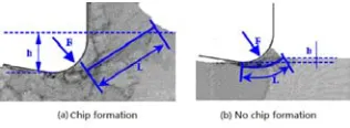
[image:4.612.227.385.343.401.2]In the mesoscopic scale, the cutting thickness is similar to the size of the tool radius , there is the phenomenon of the minimum cutting thickness, so the cutting process can be divided into two processes, they are the process of forming chips and the process of not forming chips. Kim analyze these two processes by using the molecular dynamics method, as shown in Figure 3 [5].
Figure 3. Chip formation of meso scale machining process.
When the cutting thickness is greater than the minimum cutting thickness, it will produce chips. At this point we can see from the cutting principle:
φ sin
h =
L . (22)
Where:
0 0 γ sin ξ
γ cos arctan =
φ - . ξ=ahch .
among this achis the chip thickness,his cutting thickness of the workpiece, φ is shear angle,γ0is tool rake angle.
When the cutting thickness is less than the minimum cutting thickness, no chips are generated. In this case, the length of the cutting area is obtained from the arc length of the contact portion between the tool and the workpiece in the main cutting zone, that is:
° 180 πR =
L
. (23) Where:
R h R arccos
= -
Among this R is radius of the tool.
Mechanical Properties and Scale Effect of Oxygen - free Copper
According to the standard, the oxygen content of oxygen-free copper is not more than 0.003%, the purity of copper is more than 99.95%. It commonly used for the components in vacuum electronic devices because of its high conductivity and no hydrogen embrittlement characteristics. Oxygen-free copper is relatively soft and difficult to process, therefore it is of great significance to study the mechanical properties of materials and their scale effects so as to better improve the processing parameters during micro-machining. Mechanical properties of oxygen-free copper material parameters shown in Table 1.
Table 1. Material mechanical properties (OFHC Copper).
A/MPa B/MPa N C m ∂ μ(GPa) b(nm) a T0 Tmelt
90 292 0.31 0.025 1.09 0.5 39 0.256 0.38 293 1356
For the study of mesoscopic scale effect, two cases were simulated which are considering and without considering the material scale effect under the same cutting thickness. When the uncut chip thickness is 15μm, the simulation results are shown in Figure 4, where (a) is the result of not consider the material scale effect. It can be seen from the figure that the maximum stress at this time is 277.1MPa. Figure 4 (b) is the simulation result considering the scale effect of material, and the maximum stress at this time is 373.2MPa. From the comparison of the two figures, we can see that the scale effect of the material is very obvious. Therefore, it is necessary to consider the scale effect exhibited by the material when studying the phenomenon of scale effect in micro-cutting process.
(a)Regardless of material size effect (b)Consider the material size effect
Figure 4. Results with and without consideration of size effect when uncut chip thickness is 15 μm.
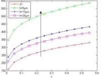
[image:5.612.257.357.466.544.2]The constitutive model of the material considering the mesoscopic scale is deduced by equations (21), (22) and (23), we can find that the material scale effect is related to the depth of cutting. The stress-strain curves of the oxygen-free copper at different depths of cutting are calculated as shown in Figure 5.
Figure 5. Materials performance curves of different cutting depth.
It can be seen from Figure 5 that with the increases of the cutting thickness, the stress decreases gradually, but the scale effect that material shows will be more obvious.
Using ABAQUS simulation software to simulate different cutting thicknesses, we can get the material stress in different depth of cutting when considering the scale effect of material in mesoscopic scale, the results are shown in Figure 6.
[image:5.612.82.528.636.700.2](a)h=5μm (b)h=15μm (c)h=25μm
Figure 6. Simulation results of different cutting depth.
increase, the stress will gradually decrease. We can get a opposite result when the cutting thickness is relatively small. It shows that the scale effect of the material is more obvious with the reduction of the cutting thickness.
Conclusion
Based on the MSG theory, the constitutive model of the material considering the mesoscopic scale cutting is deduced. By analyzing the material performance curves and simulation results obtained under different cutting conditions, the following conclusions can be drawn:
(1)Based on the material constitutive model established by MSG theory, the scale effect of material in mesoscopic scale cutting can be described. It can be found through simulation that the scale effect exhibited by the material is the reason for the scale effect during mesoscopic scale cutting. Therefore, the phenomenon of scale effect in mesoscopic scale cutting can be interpreted from the material aspect.
(2)During the micro-cutting process, with the increases of the cutting thickness, the material performance curve gradually tends to the macroscopic JC constitutive curve. However, compared with the macro-cutting, the scale effect of the material is more significant.
Acknowledgement
The project supported by the Natural Science Foundation of Shaanxi Province (No.2013JQ7009), and the Natural Science Foundation of Shaanxi Educational Committee (No.14JK1527).
Reference
[1] R.S. Anand, K. Patra. Modeling and simulation of mechanical micro-machining—A review, J. Machining Science & Technology. 18(3)(2014)323-347.
[2] Y. Huang, H. Gao, W. Nix, et al. Mechanism-based strain gradient plasticity-II. Analysis, J. Journal of the Mechanics and Physics of Solids. 48(1)(2000)99-128.
[3] Y.G. Huang, K.Z. Huang. Solid constitutive relation. Beijing: Tsinghua University Press, 1999. [4] S.N. Melkote, S.S. Joshi. An explanation for the size effect in machining using strain gradient plasticity, J. ASME Journal of Manufacturing Science and Engineering, 126(2004)679-684.