PERFORMANCE ENHANCEMENT OF A SILICON MEMS
PIEZORESISTIVE SINGLE AXIS ACCELEROMETER WITH
ELECTROPLATED GOLD ON A PROOF MASS
1
R.VARATHARAJAN , 2 A.ANGELIN PEACE PREETHI
1
Professor and Head, Department of ECE, Bharath University , Chennai.
2
Research scholar , Department of ECE, Bharath University, Chennai.
E-mail: 1 [email protected] , 2 [email protected]
ABSTRACT
This paper presents realization of MEMS piezoresistive single axis accelerometer with electroplated gold on the proof mass. The piezoresistive accelerometer shows very high sensitivity and good linearity. But performance behavior of the system shows precise effect due to cross axes sensitivity. Performance enhancement is achieved by electroplating a gold mass on top of the proof mass of dimension 2500µm X 2500µm X 30µm. This paper explains the simulation analysis using ANSYS11® and design optimization of the accelerometer structures without gold, with electroplated gold on top of the proof mass and with electroplated gold on bottom of the proof mass. From these structures, prime axis stress sensitivity, cross axes stress sensitivity and displacement of the structures have been analyzed. Test result of these devices shows that the prime axis stress sensitivity of electroplated gold with top of the proof mass is increased by 53% and the structure with top of the proof mass is increased by 49% as compared to the structure without gold. Cross axes stress sensitivity of the structure with gold on top of the proof mass along the X, Y axis is reduced by 17% and 15% with the structure without gold.
Keywords:MEMS piezoresistive accelerometer; sensitivity; linearity; ANSYS software
I. INTRODUCTION
Microelectromechanical structures and systems are miniature devices that enable the operation of complex systems. They exist today in many environments like automotive, medical, consumer, industrial and aerospace. An accelerometer sensor
plays the vital role which transforms inertial energy
to stress energy through a spring-mass system which is measured by different sensing mechanisms. There are several sensing mechanisms for accelerometers like piezoresistive, piezoelectric, capacitive, tunneling and vibrating beam/resonant beam methods [1-3]. Piezoresistive accelerometer was the first silicon accelerometer using micro machined technology [4]. They are widely used due to its structural simplicity, simple fabrication process and less prone to parasitic capacitance, electromagnetic interference etc., as compared to the other accelerometers. But the main drawbacks of the piezoresistive sensing method are large temperature sensitivity and low overall sensitivity [5].
2. DEVICE DETAILS
2.1 Piezoresistive Accelerometer Structure Without Gold
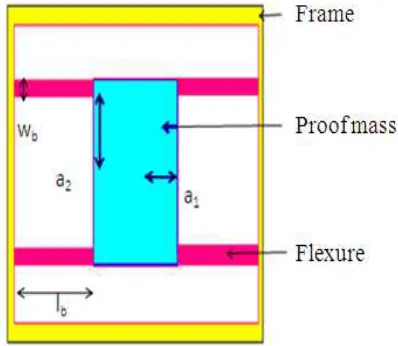
The design accelerometer consists of a proof mass suspended by four thin flexures that are fixed to an outer supporting frame along X axis is shown in the Fig 1. The dimension of various accelerometer structures are as follows
• Proof mass: 3500µm X 3500µm X
270µm
• Flexure: 1200µm X 250µm X 20µm • Gold: 2500µm X 2500µm X 20µm
[image:2.595.90.289.519.692.2]In this structure, the heavy mass is suspended at the one end of a beam and another end of the beam is fixed to its frame. The frame is fixed to the system whose acceleration is to be measured. As the system accelerates, the frame moves with it. The proof mass, due to its inertia tries to remain in its earlier position. The proof mass gets deflected up/down, depending on the direction of the motion of the system. The two types of parameters like von mises stress sensitivity and displacement of the structure is analyzed to measure the prime axis stress sensitivity of Z axis and cross axes stress sensitivity of X and Y axis. The prime axis sensitivity of the quad beam accelerator can be increased by increasing one of the following structural parameters; (a) flexure length, (b) proof mass area and (c) proof mass thickness. By increasing the proof mass thickness and the flexure length the overall device area gets increased. The proof mass thickness can be increased to achieve higher sensitivity along Z axis.
Figure 1.Structure Of Single Quad Beam Structure Without Gold
However, the flexure thickness cannot be decreased beyond certain thickness to avoid the damage in the thin flexure due to mechanical vibration and shock during dicing and subsequent packaging of the fabricated device. Flexure width cannot be decreased much, since it accommodates diffused resistors and metal interconnection lines to form the Wheatstone bridge. To solve these limitations of the structure, an alternative approach is to increase mass of the single quad beam accelerometer is as followed [6].
2.2 Electroplated Gold Piezoresistive Accelerometer
For the dimensions of (2500x2500x20) um, an addition of an extra layer is deposited on the proof mass which improves the sensitivity of the device in a desired direction and reduces the Brownian noise and transverse sensitivities [7-8]. Fig 2(a) shows the structure of the electroplated gold on top of the proof mass and Fig 2(b) shows the electroplated gold on bottom of the proof mass. The deflection (Δ z) of proof mass
of a fixed-fixed quad beam structure for Z axis acceleration is given by
∆
z=
Ma
zl
b34
Ewh
3(1) Where M is mass of the proof mass, az is the
acceleration along the Z-axis, E is the Young’s modulus, lb is the length of the flexures, w is the
width of the flexures, and h is the thickness of the flexures. The rotation of the proof mass around the X axis (θx) for Y axis acceleration is given as
2 2 3 3
4
Ewh
a
l
Z
Ma
b c y
x
=
θ
(2)
Where ay the acceleration along Y axis, Zc is is
(a) (b)
[image:3.595.90.299.106.311.2]
Figure 2.(A) Structure With Electroplated Gold On The Top Of Proof Mass (B) Structure With Electroplated
Gold On The Bottom Of Proof Mass.
The rotation of proof mass around the Y axis (θ y) for X axis acceleration is given as
(
2 2)
3
3
4
3
3
3
l b l b b
c x
y
=
Ma
Z
l
Ewh
l
+
a
l
+
a
θ
(3) Where ax is the acceleration along X- axis,
and a1 is the distance between the proof mass
centers and the proof mass edge along X direction. Stress produced on flexures and the stability along X and Y axes are directly proportional to rotation of the proof mass for X and Y accelerations. The deflection Δz is directly proportional to the mass
and inversely proportional to the height which increases the prime axes stress sensitivity and reduces the cross axes stress sensitivity.
3. SIMULATION ANALYSIS
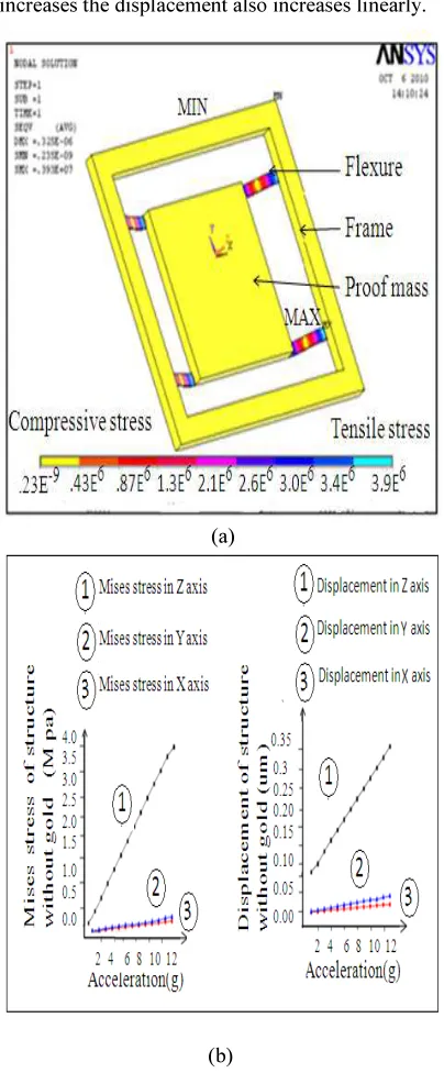
Fig 3(a) shows the simulation of the single quad beam accelerometer structure. The two types of parameters like von mises stress and displacement of the structure are analyzed. The von mises stress shows the two types of stress like tensile stress and compressive stress. The maximum stress sensitivity is experienced at the fixed ends of beam of flexures and minimum stress sensitivity is experienced at the middle of the flexures. Thus the maximum stress region shows the location of the piezoresistors in all the four flexures to maximize the piezoresistive effect. Fig 3(b) shows mises stress sensitivity Vs acceleration
of full scale acceleration upto 13g. The prime axis stress of 3.9 M Pa is increased higher as compared to the cross axes stress sensitivity of X and Y axes as 0.23 M Pa and 0.325 M Pa. When the stress increases the displacement also increases linearly.
(a)
[image:3.595.307.509.175.668.2](b)
Figure 3.Single Quad Beam Accelerometer: (A) Structural Simulation (B) Graph Of Mises Stress
And Displacement For All Z, Y And X Axes.
sensitivity was found to be 3.21um and the cross axes displacement along X and Y axes were found to be .016µm and .032µm respectively. By this we conclude that density along the prime axis sensitivity is increased higher than the cross axes sensitivity of X and Y axis.
The main causes of high cross axis sensitivity in a beam structure is due to the structural instability and asymmetrical design. In the present study, the cross axes sensitivity is further reduced by placing the flexures in line with the proof mass edges. When the flexures are placed at the exact corner edges of the proof mass, the cross axis sensitivity is reduced proportionally and prime axes sensitivity is increased drastically [9]. There are some limitations to reduce the cross axes sensitivity of the quad beam accelerometer structure based upon the parameters. So to reduce the cross axes stress sensitivity and to enhance the performance of the accelerometer the heavy gold metal for the dimensions of (2500x2500x20) µm is deposited on top or bottom of the proof mass which improves the quality factor, sensitivity and mass M. Since the bulk of gold is 8 times greater than that of silicon, the density of the material is increased higher. Many numbers of devices can run on the gold layer which provides good electrical conduction. An Addition of gold on top of the proof mass increases the mass M and allows higher reduction in “Zc” than the other structures. Besides
that there is reduction in silicon proof mass thickness and decreases the real estate consumption problem. An alternative approach is to add the gold on bottom of the proof mass which increases both “MZc” products. But the main drawback is that it
does not perform metal deposition technique during electrical conduction.
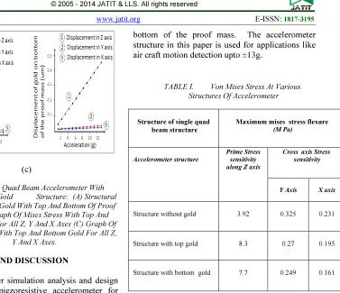
Fig 4(a) shows the simulation results of gold on top of the proof mass and gold on bottom of the proof mass along Z axes. The maximum prime axes stress sensitivity of gold at 13 g is 8.3 M Pa as compare to gold on bottom of the proof mass is 7.7 M Pa. Fig 4(b) shows the comparisons of prime axis and cross axes stress sensitivity of gold on top of the proof mass and gold on bottom of the proof mass for all Z, Y and X axes. The prime axis stress sensitivity is increased higher than cross axes stress sensitivity. The cross axes stress sensitivity along X- and Y-axes were found to be 0.270 M Pa and 0.195 M Pa of gold on top of the proof mass as compared to gold on bottom of proof mass stress sensitivity as 0.245 M Pa and 0.126 M Pa respectively. The stress is proportional to the displacement. Fig 4(b) shows the displacement
graph of gold on top of the proof mass and gold on bottom of the proof mass gold for all Z, Y and X axes. The prime axis displacement is higher than the cross axes displacement. The maximum displacement along prime axis of gold on top of the proof mass was found to be 0.465 µm as compared to gold on bottom of the proof mass as 0.445 µm. Thus single quad beam of the electroplated top gold structure was compared with the bottom gold structure and the result shows that the top gold structure performance improved better than both the bottom gold structure and also the structure without gold.
(a)
(c)
Figure 4.Single Quad Beam Accelerometer With Electroplated Gold Structure: (A) Structural
Simulation Of Gold With Top And Bottom Of Proof Mass (B) Graph Of Mises Stress With Top And Bottom Gold For All Z, Y And X Axes (C) Graph Of Displacement With Top And Bottom Gold For All Z,
Y And X Axes.
4. RESULTS AND DISCUSSION
In this paper simulation analysis and design optimization of piezoresistive accelerometer for various single quad beam-mass structures like electroplated gold on the top of the proof mass, gold on bottom of the proof mass and the structure without gold is presented in terms of maximum displacement of proof mass, prime axis stress and cross axes stress sensitivity using FEM based simulation software ANSYS11®. Table I shows the test result measurements to evaluate the performance enhancement of the accelerometer. The gold on top of the proof mass and gold on bottom of the proof mass structure shows the significant maximum prime axis stress sensitivity of 53% and 49% as compare to the structure without gold. The gold on top of the proof mass cross axes stress sensitivity along X and Y axes are reduced by 16% and 11% respectively. In piezoresistive accelerometers, the resistance change is proportional to the developed stress which in turn directly proportional to the displacement of the proof mass. From the Fig 4(b) the graph shows that the gold at top of the proof mass structure has the maximum increase stress sensitivity of 0.465µm along Z axes as compared to the structure with gold on the bottom of the proof mass and the structure without gold as 0.445 µm and 0.321 µm. This is because the displacement of the proof mass is directly proportional to mass “M” following the equation 1. The gold on top of the proof mass increases the higher reduction in Zc than gold at
[image:5.595.159.536.94.419.2]bottom of the proof mass. The accelerometer structure in this paper is used for applications like air craft motion detection upto ±13g.
TABLE I. Von Mises Stress At Various Structures Of Accelerometer
Structure of single quad beam structure
Maximum mises stress flexure (M Pa)
Accelerometer structure
Prime Stress sensitivity along Z axis
Cross axis Stress sensitivity
Y Axis X axis
Structure without gold 3.92 0.325 0.231
Structure with top gold 8.3 0.27
.
0.195
Structure with bottom gold 7.7 0.249 0.161
5. CONCLUSION
Realization of bulk micromachined piezoresistive accelerometer is presented in this paper. The accelerometer structure consists of a suspended proof mass surrounded by four thin flexures was simulated using ANSYS11®. To enhance the performance of the silicon piezoresistive accelerometer the electroplated gold at the dimention of 2500µmx2500µmx30µm was deposited on the top or bottom of the proof mass. The prime axis stress sensitivity of gold on the top of the proof mass is increased by 53% and gold on bottom of the proof mass is increased by 43% as compared to the structure without gold. Cross axes sensitivity also further reduced by 16% and 11% with the structure without electroplated gold . From this gold on top of the proof mas provides higher performance good electrical conduction than the other structures.
ACKNOWLEDGMENT
staff members of MEMS and Microelectronics laboratory, IIT Kharagpur for their help at various stages in realization of the sensors. The authors thank the support from Ms. Ashvini, Ms. Linda Mary Jacob for their help in preparing the manuscript.
REFERENCES:
[1] T. Suminto, “A simple, high performance Piezoresistive accelerometer,” Transducers’91, pp. 104-1 07, 1991.
[2] Seidel, et al., “Capacitive silicon accelerometer with highly symmetrical design,” Sensors and Actuators, A2 1-A23, pp.
[3] Motamedi, “Acoustic accelerometers,” IEEE Trans.Ultrason. Ferroelec. Freq. Contr., UFFC-34, no.2, pp. 237-242, 1987.36 [4] Petersen K E, Shartel A and Raley N F 1982
Micromechanical accelerometer integrated with MOS detection circuitry IEEE Trans. Electron Devices 29 23–7.
[5] H. Chen, M. Bao, H. Zhu, S. Shen, A piezoresistive accelerometer with a novel vertical beam structure, Sens. Actuators 63 (1997) 19–25.
[6] J.A. Plaza, H. Chen, J. Esteve, E. loraTamayo, New bulk accelerometer for triaxial detection, Sens. Actuators 66 (1998) 105–108.
[7] F. Pan, E. Kubby, A.T. Tran, S. Mukherjee, Squeeze film damping on the dynamic response of a MEMS torsion mirror, J. Micromech. Microeng. 8 (1998) 200–208. [8] L .M. Roylance and J.B. Angell, A batch
fabricated silicon accelerometer, IEEE Trans. Electron Devices, ED-26 (197) 1911-1917.
[9] Petersen K E, Shartel A and Raley N F 1982 Micromechanical accelerometer integrated with MOS detection circuitry IEEE Trans. Electron Devices 29 23–7.Yazadi N, Najafi K and Salian A S 2003 A high-sensitivity accelerometer with a folded-electrode structure J.Microelectromech. Syst. 12 479– 86
[10] J.-H. Sim, C.-S. Cho, J.-S. Kim, J.-H. Lee, J.-H. Lee, Eight-beam piezoresistive accelerometer fabricated by using a selective poroussilicon etching method, Sens. Actuators A 66 (1998) 273–278.
[11] K. Okada, Tri-axial piezoelectric accelerometer, Tech. Digest, 8th Int. Conf. Solid-state Sensors and Actuators (Transducers ’95/Eurosensros IX),
Stockholm, Sweden, 25–29 June, 1 (1995) 554–557.
[12] J.J. Pak, A.E. Kabir, G.W. Neudeck, J.H. Logsdon, A bridge-type accelerometer using merged epitaxial lateral overgrowth for thin silicon beam formation, Sens. Actuators, A 56 (1996) 267–271.
[13] Wang Z, Zong D, Lu D, Xiong B, Li X, Wang Y (2003) A silicon micromachined shock accelerometer with twin-mass-plate structure. Sens Actuators A Phys 107:50–56. doi:10.1016/S0924-4247(03)00270-X
[14] Kal S, Das S, Maurya DK, Biswas K, Ravi Sankar A, Lahiri SK (2006) CMOS compatible bulk micromachined silicon piezoresistive accelerometer with low off-axis sensitivity. Microelectron J 37:22–30. doi:10.1016/j.mejo.2005.06.020
[15] Dong H, Jia Y, Hao Y, Shen S (2005) A novel out-of-plane MEMS tunneling accelerometer. Sens Actuators A Phys 120:360–364.doi:10.1016/j.sna.2004.12.021.
[16] Plaza J A, Chen H, Esteve J and Lora-Tamayo E 1998 New bulk accelerometer for triaxial detection Sensors Actuators A 66 105–8.