Journal of Theoretical and Applied Information Technology 20th January 2013. Vol. 47 No.2
© 2005 - 2013 JATIT & LLS. All rights reserved.
ISSN: 1992-8645 www.jatit.org E-ISSN: 1817-3195
A NEW COMBINATION METHOD OF FIREFLY
ALGORITHM AND T2FSMC FOR MOBILE INVERTED
PENDULUM ROBOT
1,2MARDLIJAH , 1ACHMAD JAZIDIE, 2BASUKI WIDODO, 1 ARI SANTOSO
1
Department of Electrical Engineering
Institut Teknologi Sepuluh Nopember (ITS), Surabaya-Indonesia
2
Department of Mathematics
Institut Teknologi Sepuluh Nopember (ITS), Surabaya-Indonesia
E-mail: [email protected]
,
2[email protected],
3[email protected], 4[email protected]
ABSTRACT
T2FSMC has succesfully overcome the chattering and robustness problems implementing on mobile inverted pendulum robot. The remaining drawback is the gain scale factor of controller determination of Fuzzy Type 2 that is still doing trial and error. Firefly Algorithm will be used in this paper to determine the best gain scale factor of controller of Fuzzy Type 2 automatically. Utilized as objective function is the ITAE Value of resulted response signal representing firefly light. It is proved from the simulation that the proposed method can effectively resulting optimal gain scale factor and the controller can solve chattering problem more effectively and more robust against disturbances and parameter uncertainties compared with trial error based.
Keywords: FireFly Algorithm, Fuzzy Sliding Mode Control, Mobile Inverted Pendulum Robot.
1. INTRODUCTION
Mobile Inverted Pendulum Robot (MIPR) is an example of very important non linear model that gained lot of interest recently [1, 2, 3, 4, 5, 6, 7]. One reason of the popularity is the ability to balance on two wheels and spin on the spot. These capabilities have the potential to solve a number of challenges in industries and society. The use of linear control method such as PID in controlling mobile inverse pendulum robot – which is naturally non linear- undoubtly cause disadvantage such as low robustness against parameter uncertainty.
Several techniques used fuzzy logic systems (FLS) [4,11,12] to deal with systems having dynamics that are not so well understood and which have models can not be so accurately established. Combine with sliding mode control, Fuzzy Sliding Mode Control (FSMC) can not fully handle the chattering caused by uncertainties and disturbances. The reason is the rules in a FLS type 1 is quite deterministic. This causes Type-1 FLS are unable to directly handle towards the rule of uncertainties, making they are so sensitive against disturbance or
Journal of Theoretical and Applied Information Technology 20th January 2013. Vol. 47 No.2
© 2005 - 2013 JATIT & LLS. All rights reserved.
ISSN: 1992-8645 www.jatit.org E-ISSN: 1817-3195
three parameters, while GA convergence is influenced by four parameters) [19,20,21,22].
2. METHODOLOGY
2.1 Developing Combined Firefly-T2FSMC Method
In our former paper [23] we use Fuzzy type 2 in combining with SMC in order to achieve smoother chattering and faster convergence. The drawbacks still exist in determining the gain scale factor which is still trial error. In this paper, Fire Fly Algorithm will be used to determine that parameter automatically. The block diagram of the T2FSMC combined with Fire Fly Algorithm is depicted as follows.
s e= +λe ( ) d x t ( ) x t
Reference Input
Non Linear System ( ) d t
Disturbance
( ) x t
Interval Type 2 Fuzzy Sliding Mode Control (IT2FSMC) Optimized by FireFly Algorithm
SMC IT2FL
FireFly Algorithm
Objective Function
0
0 ( )
simulation
simulation
t i
t t
ref measure t
f x t dt t dt
θ θ θ
= ∆
= −
∫
∫
f K s
K
Fig. 1. Block Diagram Of Fire Fly-T2FSMC
As seen at Fig. 1, the control system is still the same as used in our former paper [23] except we add firefly algorithm to compute the gain scale factors Ks and Kf. Both of these constants were
determined trial error in our previous paper. Used as objective function is the integral of time multiplied by absolute error (derived from ITAE concept) which is inversely proportional to the sense of light in a firefly. It is mean that the firefly algorithm will continuously modify the values of Ks and Kf until the objective function is minimum
or in other word the brightest firefly light already been achieved.
Used as inputs are the reference variable xd(t) –
represent the desired position and angle of MIPR and output feedback x(t) – represent the real position and angle of MIPR- resulting an error e. Those are used to compute the sliding surface s. In spite of using analityc SMC formulae, we adopt Mamdani type fuzzy reaching control, as which is used by Zhu et.al [12, 18] in computing the following control signal:
(1)
Where is a gain scale factor for control signal uf, the output of fuzzy.The fuzzy output variable,
is continuously adjusted using an if-then rule-base with respect to s. A big values of gain scale factors (Ks and Kf) will force the state trajectories
to approach the sliding surface (s=0) rapidly; but unfortunately at the same time, the chattering is excited. Therefore, the switching gain should be correspondingly increased and vice versa in a proper manner by using the firefly algorithm. In executing the above rules, the stability will be guaranted if the reaching condition
which is derived from Lyapunov Stability Criterion is fulfilled [16,18].
Fuzzy type 2 is used because of its range characteristic advantage which is very suitable in dealing with the values uncertainties of s caused by the plant parameter uncertainties and disturbances influences. It can also reduce the number of the fuzzy rules compared with Type 1. A general T2FLS is depicted at Fig. 2 [13, 14, 15]. It is similar to T1FLS except the defuzzifier block of a T1 FLS is replaced by the output processing block in a T2 FLS. That block consists of type-reduction (TR) followed by defuzzification.
Fuzzifier
Inference
Defuzzifier
Rulebase
Rulebase
Type Reducer Crisp
Input X
Type-2 input Fuzzy set
Type-2 output
Fuzzy set
Type-1 Fuzzy
Reduced set Output Y Output
[image:2.612.100.307.277.368.2]Processing
Fig. 2. Block Diagram of T2FLS
To guarantee better performance against chattering, the concept of smallest ITAE sum value is used to determine the values of gain scale factors Ks and Kf as will be discussed at the next section.
2.2 Membership and Rules of T2FSMC
[image:2.612.322.547.358.497.2]Journal of Theoretical and Applied Information Technology 20th January 2013. Vol. 47 No.2
© 2005 - 2013 JATIT & LLS. All rights reserved.
ISSN: 1992-8645 www.jatit.org E-ISSN: 1817-3195
-10 -8 -6 -4 -2 0 2 4 6 8 10
0 0.1 0.2 0.3 0.4 0.5 0.6 0.7 0.8 0.9 1
NB NM NS Z PS PM PB
D
egr
ee of
M
em
ber
s
hi
p
[image:3.612.85.532.61.731.2]Membership Function of S
Fig.3. Membership Function Of S’
TABLE I
Rule - Base Of Type2FSMC For X (MIPR Position)
S’
NB NM NS Z PS PM PB
Uf PB PM PS Z NS NM NB
TABLE 2
Rule - Base Of Type2FSMC For Theta (MIPR Angular)
’
NB NM NS Z PS PM PB
Uf NB NM NS Z PS PM PB
2.3 Firefly Algorithm
The basic theory of Firefly can be found completely at ref. [19, 21, 22]. Here we straightly describe the proposed algorithm used -shown at Figure 4- as follows:
1. Input the data of Mobile Inverted Pendulum Robot consist of parameter and refence point.
2. Input the Fireflies parameters: α, γ, β0,
Population number of firefly (n) and Maximum Iteration.
3. Input the Membership Function of Type 2 Fuzzy Sliding Mode Control (T2FSMC) 4. Generate initial population of fireflies as
1 2
[ , ,..., ] [ , , , ]
i i i i
id i i id s f sx fx
x = x x x = Kθ K θ K K
where
, , ,
i i i i
s f sx fx
Kθ Kθ K K are Gain Scale factors
Ks and Kf for MIPR angle and position
respectively.
5. By using membership function and rules determined in section B, the driving force U, the riil position and angle of the MIPR can be determined.
6. Calculate the objective function for individu xi which is based on ITAE by
using
0
0
( )
simulation
simulation
t
i t
t
ref measure t
f x t dt
t dt
θ
θ θ
= ∆
= −
∫
∫
subject to
min max
min max
min max
min max
i
i i
i
s s s
f f f
sx sx sx
fx fx fx
K
K
K
K
K
K
K
K
K
K
K
K
θ θ θ
θ θ θ
≤
≤
≤
≤
≤
≤
≤
≤
Notate the objective function for individu xi as Ii and it should be computed for all
fireflies inside the initial population. The objective function represent the fitness of the Firefly that is the light intensity.
7. Modify the fitness by following iteration: while t ≤ Maximum Iteration
for i = 1 : n for j = 1 : n if (Ii < Ij)
(
2)
0
1
* exp * * ( ) *
2
i i ij j i
x = +x β −γ r x −x +a rand−
end
repeat 5th and 6th steps end
end
rank the fireflies and find the current best end
with:
rijisattractiveness varies defined as:
2
, ,
1
(
)
d
ij i j i k j k
k
r
x
x
x
x
=
=
−
=
∑
−
xi,k is the-kth component of spatial
coordinat of ith firefly xi and d is the
ISSN: 1992-8645 www.jatit.org E-ISSN: 1817-3195
* 0
( )
r
exp(
r
m)
β
=
β
−
γ
, is theattractiveness fungtion with m
≥
1. γ is the absorbtion coefisien controlling thereduction of firefly light intensity. 8. Stop and postprocess result and
visualization.
Input data of MIPR parameters and fireflies parameters Define objective function : f (xi) = ITAE
Generate initial population of fireflies
fori = 1 : all fireflies
forj = 1 : all fireflies if (Ij > Ii)
Move firefly i towards j in d-dimension; end
Attractiveness varies with distance r via exp[−γr] Evaluate new solutions
Interval Type 2 Fuzzy Sliding Mode Control (IT2FSMC)
Update light intensity determined by objective function f (xi)
end end
Light intensity Ii at xi is determined by objective function f (xi) Define light absorption coefficient γ
Rank the fireflies and find the current best
It < MaxIt ?
Stop and Postprocess results and visualization 1 2
[ , ,..., ] [ , , , ]
i i i i
id i i id s f sx fx
x = x x x = Kθ Kθ K K
It=1
It = It +1 Interval Type 2 Fuzzy Sliding Mode Control (IT2FSMC)
Fig.4 Flowchart Of The Proposed Method (T2FSMC Optimized By Firefly Algorithm)
2.3 Mathematical Model of Mobile Inverted Pendulum Robot
The plant chosen in implementing of the IT2FSMC is mobile inverted pendulum robot, as can be seen at Figure 5. It consists of three subsystems, DC motor, Wheel, and chassis.
Fig.5 Mobile Inverted Pendulum Robot[2]
The mathematical model of this plant is as follows.The first subsystem motor DC model :
m m e
R a R
r r
m m e
L a L
L L
k
k k
V
Ja R
Ja R
k
k k
V
Ja R
Ja R
ω
ω
ω
ω
=
−
=
−
(2)The second subsystem wheel model :
2 2
2 2
w m m e
w R aR R R drR
w m m e
w L aL L L drL
J k k k
M x V x H f
r Rr Rr
J k k k
M x V x H f
r Rr Rr
+ = − − + + = − − + (3) The thirth subsistem chasis model :
cos sin
2e m p m m cos p
aR aL dp
M l M gl
k k k k l
x x V V f
rR R R
θ θ θ
θ= γ − γ −γ −γ + γ − γ
2 2
cos sin
2m e p m m drR drL dp p
aR aL
M l f M l
k k k k f f
x x V V
Rr Rr Rr
θ θ θ
θ
α α α α α α α α
= − − + + + + + +
(4) From equations 2, 3, and 4 the whole equations of the system can determined like this :
(
)
2 22
2 2 ( )
e m p p m p
p drR drL dp
k k M lr M l g k M lr
x x V
Rr Rr
J
f f f
γ γ
φ
β β β
γ γ
β β β
− − = + + + + + (5) 2
2 ( ) 2 ( )
e m p p m p
p p p
dr R dr L dp
k k r M l M gl k M l r
x V
Rr Rr
M l M l M l l
f f f
α α α
φ φ
β β β
γ α
β β γβ
− − = + + − + + + (6) where 2 2
2
wp p w
J
J
M l
M
r
β
=
α
+
+
Or in the state space model can be written as follows:
1 1
2 2
3 3
4 4
0 1 0 0 0 0 0 0
0 22 23 0 21 21 22 23
0 0 1 0 0 0 0 0
0 42 43 0 41 41 42 43
drr a drl dp f V f f x x
x A A x B Q Q Q
x x
x A A x B Q Q Q
Journal of Theoretical and Applied Information Technology 20th January 2013. Vol. 47 No.2
© 2005 - 2013 JATIT & LLS. All rights reserved.
ISSN: 1992-8645 www.jatit.org E-ISSN: 1817-3195
2 2
23 p
A M l g
β
=
(
)
2
22 2 e m p ;
A k k M lr Rr
γ β
= −
43 M glp
A α
β =
2 ( )
42 2 ;
k ke m r M lp A
Rr
α β
− =
2 ( )
41 km M lp r B
Rr α β
− =
41 42 M lp
Q Q
β
= =
21 22 ;
Q Q γ
β
= =
43 M lp l
Q γ α
γβ
− =
23 Jp; Q
β
= 1
x = position of MIPR,
2 x
= angle of pendulum of MIPR,
3
x = velocity of MIPR, and
4
[image:5.612.89.525.69.624.2]x = angular velocity of MIPR.
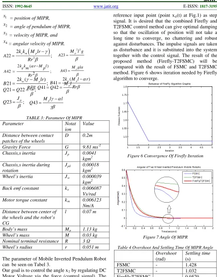
TABLE 3: Parameter Of MIPR
Parameter Notat
ion
Value
Distance between contact patches of the wheels
D 0.2m
Gravity Force G 9.81 ms-2
Chassis,s inertia Jp 0.0041
kgm2 Chassis,s inertia during
rotation
Jpδ 0.00018
kgm2
Wheel’s inertia Jw 0.000039
kgm2
Back emf constant ke 0.006087
Vs/rad
Motor torque constant km 0.006123
Nm/A Distance between center of
the wheels and the robot’s CG
l 0.07 m
Body’s mass Mp 1.13 kg
Wheel’s mass M 0.03 kg
Nominal terminal resistance R 3 Ω
Wheel’s radius r 0.051 m
The parameter of Mobile Inverted Pendulum Robot can be seen on Tabel 3.
Our goal is to control the angle x2 by regulating DC Motor Voltage via the force (control signal). The detail relationship between control signal and DC Motor Voltage has been derived as seen at ref [1,2,3].
3. SIMULATION AND RESULT ANALYSIS
The above model together with other blocks of T2SMC and Firefly will be simulated using Matlab Simulink. The triggering signal is given at
reference input point (point xd(t) at Fig.1) as step signal. It is desired that the combined Firefly and T2FSMC control method can give optimal damping so that the oscillation of position will not take a long time to converge, no chattering and robust against disturbances. The impulse signals are taken as disturbance and it is substituted into the system together with the control signal. The result of the proposed method (Firefly-T2FSMC) will be compared with the result of FSMC and T2FSMC method. Figure 6 shows iteration needed by Firefly algorithm to converge.
1 1.5 2 2.5 3 3.5 4 4.5 5
1.5 1.55 1.6 1.65 1.7 1.75 1.8
Behaviour of FireFly Algorithm Graphic
Iteration
F
it
nes
s
F
unc
ti
on
Figure 6 Convergence Of Firefly Iteration
Figure 7 Angle Of MIPR
Table 4 Overshoot And Settling Time Of MIPR Angle
Overshoot (rad)
Settling time (s)
FSMC - 1.428
T2FSMC - 1.032
FireFlyT2FSMC - 0.9579
Figure 7 shows the result of the angle of the MIPR as a response against impulse trigger signal. It is clearly shown that the angle response, which is resulted using the proposed method (Firefly-T2FSMC), is much more accurate with smaller settling time compared with from FSMC and T2FSMC (look also Table 4). Figure 8 represents the response of angular speed. Here, the settling
2 ( )
21 km M lrp
;
BRr
γ
β
ISSN: 1992-8645 www.jatit.org E-ISSN: 1817-3195
time of the proposed method is smallest (see table 5) but the overshoot is slightly higher than T2FSMC.
Figure 8 Angular Speed Of MIPR
Table 5 Overshoot And Settling Time Of MIPR Angular Speed
Overshoot (rad/s)
Settling time (s)
FSMC -3.971 1.292
T2FSMC -2.799 1.001
FireFlyT2FSMC -3.145 1.0
Figure 9 describe the response of position of MIPR. As can be seen, there are no overshoots for T2FSMC and Firefly- T2FSMC although it is high enough for FSMC. The time settling of proposed method is slightly better as shown at Table 6.
Figure 9 Position Of MIPR
Table 6 Overshoot And Settling Time Of MIPR Position
Overshoot (m)
Settling time (s)
FSMC 1.189 (0.189
from ref 1 m) 1
T2FSMC - 0.5376
FireFlyT2FSMC - 0.5370
Figure 10 describe the response of speed of MIPR. As can be seen, the overshoots of the proposed method is slightly higher compared with T2FSMC but the time settling of proposed method is slightly better as shown in Table 7.
Figure 10 Speed Of MIPR
Table 7 Overshoot And Settling Time Of MIPR Speed
Overshoot (m/s)
Settling time (s)
FSMC 5.046 1.192
T2FSMC 7.346 0.5451
FireFlyT2FSMC 7.856 0.5449
Table 8 shows the comparison of ITAE values among three discussed methods for MIPR angle. It can be seen from this table that the ITAE values of the proposed method are smaller than the other two methods, which guarantees that the proposed method - Firefly-T2FSMC - has a faster convergence which is proven by the simulation results. In general, it can be concluded that related to robustness or overshoot, the performance between Firefly-T2FSMC and T2FSMC is more and less the same. This is caused by the fact that we use the same rules and membership function. Anyway, the difference mechanism in determining the optimal values of gain scaling factors make the proposed method superior with faster time settling.
Table 8 Values Of ITAE
ITAE
FSMC 9.6516
T2FSMC 20.5175
FireFlyT2FSMC 1.475
4. CONCLUSION
Journal of Theoretical and Applied Information Technology 20th January 2013. Vol. 47 No.2
© 2005 - 2013 JATIT & LLS. All rights reserved.
ISSN: 1992-8645 www.jatit.org E-ISSN: 1817-3195
why if related to robustness or overshoot, the performance between Firefly-T2FSMC and T2FSMC is more and less the same. This is caused by the fact that we use the same rules and membership function. The use of firefly algorithm in determining the optimal values of gain scaling factors automatically make the proposed method superior with faster time settling compared with other methods. The firefly algorithm also successful in solving the drawback of the former method (T2FSMC) -which is still trial-error in determining the gain scale factors- resulting shorter simulation time.
REFERENCES
[1] Ooi, R.C., “Balancing a Two-Wheeled Autonomous Robot”, B.Sc. Final Year Project, University of Western Australia School of Mechanical Engineering, Australia.2003.
[2] Grasser, F., D’Arrigo, A., Colombi, S., Rufer, A.C. “JOE: A Mobile Inverted pendulum”, IEEE Transactions on Industrial Electronics, 49(1), 2002: pp107-114.
[3] Abdollah, M.F.,”Proportional Integral Sliding Mode Control of a Wheeled Balancing Robot”, Master Engineering Thesis., University Teknologi Malaysia, Malaysia. 2006
[4] Jafar Keighobadi, Yaser Mohamadi, “Fuzzy Sliding Mode Control of a Non-Holonomic Wheeled Mobile Robot”, Proceeding of the International MultiConference of Engineers and Computer Scientist 2011 Vol II, IMECS 2011, March 16-18, 2011, Hong kong
[5] N. M. Abdul Ghani, N. I. Mat Yatim, N. A. Azmi, “Comparative Assessment for Two Wheels Inverted Pendulum Mobile Robot Using Robust Control” International Conference on Control, Automation and System 2010 Oct 27-30, 2010 in KINTEX, Gyeonggi-do, Korea
[6] S.W. Nawawi, Ahmad M. N, and Osman J.H.S, “Variable Structure Control of Two-Wheels Inverted Pendulum Mobile Robot”, Regional Postgraduate Conference on Engineering and Science (RPCES 2006), Johore, 26-27 July
[7] Anderson, D.P, “Nbot, a two wheel balancing robot”, Available from :<
http://www.geology.smu.edu/~dpa-www/robo/nbot/ >2003
[8] J. E. Slotine and S. S. Sastry, “Tracking control of non linear system using sliding
surfaces with application to robot manipulator”, International Journal of Control, vol.38,no. 2,1983.
[9] Mardlijah, Lusiana P, MH Purnomo, “Design and Performance Analysis of Speed Controller in Induction Motor with Sliding Mode Control”, Proceeding of ICRG 2010, UGM Yogyakarta
[10] Y. K. Kim and G. J. Jeon, “Error Reduction of Sliding Mode Control Using Sigmoid-Type Nonlinear Interpolation in the Boundary Layer”, International Journal of Control,
Automation, and Systems, December 2004,
vol. 2,523-529
[11] Jiwei W, Lihong X, Yunshi X.,” A New design method of Fuzzy Sliding Mode Controller with faster convergence”, IEEE
Int. Fuzzy Systems Conference Proceedings,
1999
[12] Zhu, F.Q., Q.M. Winfield, A., and Melhuish, C. “Fuzzy Sliding Mode Control for Discrete Nonlinear Systems”. Transactions of China
Automation Society, Vol. 22, No. 2,2003
[13] M.Y. Hsiao, Tzuu Hseng S, JZ Lee, CH. Chao, SH Tsai, “Design of interval type 2 fuzzy sliding mode controller”, International
Journal of Information Sciences. 178 (2008)
[14] JR Castro, Oscar Castillo, LJ Martinez, “Interval Type 2 Fuzzy Logic Toolbox”,
Engineering Letters, Mexico, 2007.
[15] J. Mendel, “Uncertain Rule-based Fuzzy Logic Systems: Introduction and new directions, “N J : Prentice Hall 2001.
[16] Perruquetti, W and Barbot J.P., “Sliding Mode Control in Engineering”, Marcell Dekker, New York, 2002.
[17] S.W. Nawawi, Ahmad M. N, and Osman J.H.S, “Variable Structure Control of Two-Wheels Inverted Pendulum Mobile Robot”, Regional Postgraduate Conference on
Engineering and Science (RPCES 2006),
Johore, 26-27 July
[18] Palm, R., Driankov, D dan Hellendoorn, H, (1997), “Model Based Fuzzy Control: Fuzzy Gain Schedulers and Sliding Mode Fuzzy Controllers”, Spinger-Verlag., Berlin.
[19] Yang, X-S. “Nature-Inspired Metaheuristic Algorithm”. Luniver Press.2008
[20] Apostolopoulos,T., and Vlachos,A., ”Application of the Firefly Algorithm for Solving the Economic Emissions Load Dispatch Problem”, International Journal of
Combinatorics, Volume 2011, Hindawi
ISSN: 1992-8645 www.jatit.org E-ISSN: 1817-3195
[21] X. S. Yang, “Firefly algorithm, stochastic test functions and design optimisation,”
International Journal of Bio-Inspired
Computation, vol. 2, no. 2, pp. 78–84, 2010.
[22] X. S. Yang, “Firefly algorithm, Levy flights and global optimization,” in Research and
Development in Intelligent Systems XXVI, pp.
209–218, Springer, London, UK, 2010. [23] Mardlijah, Abdillah,M, Jazidie,A ,Widodo,B.,
Santoso,A.,” Performance Enhancement of Inverted Pendulum System by Using Type 2 Fuzzy Sliding Mode Control (T2FSMC)”, International Conference on Electrical Engineering and Informatics