BLADE LOAD CONTROL OF WIND TURBINE BASED ON
VARIABLE-PITCH CONTROL STRATEGIES
HAIJUN REN
Automation Institute of Chongqing University of Posts and Telecommunications, Chongqing 400065,
Chongqing, China
ABSTRACT
The control strategies of blade loads are proposed for the characteristics of blade stresses of variable-speed variable- pitch wind turbine. Blade loads are divided into two static and dynamic components. The pitch angle and generator torque are controlled by Single neuron PID controller in the static part. Variables are converted from rotational coordinate to fixed coordinate through multi-blade coordinate transformation theory. Then, the control parameters obtained are converted to the one in rotational coordinate frame via multi-blade inverse transformation in the dynamic part. The parameters of static part are added to the parameters of dynamic part, yielding control value for wind turbine pitch control. The external controller of Bladed is designed and the control strategies are simulated by the professional design software Bladed for wind turbines. The control performance of external controller is compared with and that of internal controller. Simulation results show that external controller can reduce the tilt torque of blade root and blade flapwise torque. Thus the proposed external controller possesses a better performance, the correctness of the proposed blade load control strategies is verified.
Keywords: Wind Turbine, Variable-pitch System, Coordinate Conversion, Load Control
1. INTRODUCTION
The vibration occurs easily because that the span-wise is longer more than the chord-span-wise of the blade, in which stresses are very complex due to the variability of wind speed in the temporal and spatial. Vibration should produce deformation and moving load, the wind turbines are fail so that reducing the loads of wind turbines became one of problems solved urgently[1-5].
After scholars effort, some achievements are obtained in reducing load. The loads of wind turbines are analyzed through the perspective of closed loop in some literature and the loads are reduced due to adopt neural network, robust control and other advanced control theories[1-2]. Many factors are considered reducing the load in other literature, in which the literature [3] has considered reducing the vibration load of tower in the pitch system and motor torque control process. This multivariable control strategy is realized by combining a nonlinear dynamic state feedback torque control strategy with a linear control strategy for blade pitch angle to reduce the control load for actuator in [4]. An optimal multivariable LQG controller and a feed-forward disturbance rejection controller are designed to reduce the fatigue load of wind turbine. The LQG controller can minimize the rotor tilt and yaw moments and the feed-forward
controller can improve the rotor moments in the low-frequency components in [5].The power of wind turbine is controlled by the method of variable-pitch variable-speed above rated wind speed, and just as the blade angle of attack is changed during variable-pitch, the load of blade is changed. Therefore, the blade load is divided into two static and dynamic components. Since single neuron PID controller with self-learning and adaptive ability can adjust the controller parameter on line, static load is determined through the single neuron PID controller to regulate the pitch angle in this state. In order to obtain the dynamic load, variables are converted from rotational coordinate frame to fixed coordinate frame through multi-blade coordinate transformation. Then, the control parameters obtained are converted to the one in rotational coordinate frame via multi-blade inverse transformation in the part of dynamic load. The parameter of static part is added to the parameter of dynamic part, yielding control value for wind turbine pitch control.
2. SINGLE NEURON PID CONTROL OF VARIABLE-SPEED VARIABLE-PITCH WIND TURBINE STATIC LOAD
2.1Theory analysis of wind turbine pitch system
Wind turbine converts wind energy into mechanical energy, the energy obtained in [6] can be formulated in [6-7].
1 3
( , ) 2
P v SC
p
ρ λ β
= (1)
Where Pis the shaft power of wind turbine, ρ
is the air density,v is the wind speed,S is the
swept area of wind wheel,Cp( , )λ β is the energy
conversion coefficient of wind turbine. Energy conversion factor is expressed as a formula (2) in [7].
12.5
3
116
( , ) 0.22( 0.4 5)
1 1 0.035
0.08 1
i
p
i
i
C e
R v
λ
λ β β
λ
λ λ β β
ω λ
−
= − −
= −
+ +
=
(2)
Whereλ is the tip speed ratio,β is the pitch
angle,ω is the speed of wind wheel,R is the radius
of wind wheel.
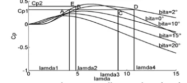
In general, the relationship among the λ、Cp
and β , respectively, tip speed ratio - wind energy
conversion coefficient- pitch angle diagram, as
shown in Figure 1, where lamda is λ.When the
power conversion coefficient for wind turbine is
1
p
C , four intersection points are in the figure 1,
each point for A, B, C, D. Cp1 and the curve for
pitch angle is 0° intersects at A and C, A and C are respectively corresponding to the tip speed ratio
lamda1 and lamda3, where lamda1<lamda3. Cp1
and the curve for pitch angle is 2° intersects at B,
and D. B and D are respectively corresponding to the tip speed ratio lamda2 and lamda4, where lamda2<lamda4.Consequently, changing the angle and tip speed ratio to maintain the power conversion coefficient of wind turbine at a constant value. When the tip speed ratio is lamda2,
intersections B and E are respectively
corresponding to the pitch angle of 2 °,and 0
°,which corresponding power conversion
coefficient is Cp1<Cp2. Furthermore, maintaining tip speed ratio at a constant, the different power coefficients can be gained through regulating pitch angle. Furthermore, when pitch size unchanged, the different power coefficients can be obtained by
[image:2.612.326.515.159.243.2]adjusting the tip speed ratio value in curve section AE. Therefore, the different power coefficients can be obtained by regulating pitch angle or adjusting tip speed ratio, finally, the output power of wind turbine can be regulated.
Figure 1: Curves Of Energy Coefficient Of Wind Turbine
2.2 Model of pitch system
The power can be regulated by the blade itself
aerodynamics if not for the active control when wind speed is higher than the rated value of wind turbine. But this method is used for small wind turbine. The output power is maintained at the rating through changing pitch angle for large wind turbine. Formula (3) expresses the model of wind turbine of variable-speed variable-pitch in [8].
1
( ')
1
( )
e
c ins
T T J
t
ω
θ θ θ
⋅
⋅
= −
= −
(3)
Where ω
⋅
is the angular acceleration, J is the
moment of inertia of wind wheel, '
e
T is the torque
of conversion to the low speed shaft,θ
⋅
is the actual
acceleration of pitch angle,tins is the time constant
of pitch mechanism,θc is the command value of
pitch angle,θ is the actual value of pitch angle.
From R
v
ω
λ= to:
v R
λ
ω = (4)
2 2
1 1
2 p 2 T
T ρSC Rv ρSC Rv
λ
= = (5)
Here, CT Cp
λ
= .
'
e
T has a different selection method. In order to
simplify the model and obtain better system
performance, '
e T
is obtained by converting rated value of generator torque.
2.3.1 Control system of static load
When the actual power above rated power
value, PID controller regulates the deviation, the output power of wind turbine is maintained at the rated value. Because the pitch is actually the process of changing the blade angle of attack, also changes the blade force, then the blade load should be controlled. Blade loads have been divided into two static and dynamic components. The pitch angles are regulated by PID controller in the static part. When the wind changes, the static desired
pitch angle,θs,is obtained by speed Ω calculating
[image:3.612.91.297.268.331.2]parameters because the wind speed can not jump. Pitch control diagram is shown in Figure 2.
Figure 2: Pitch Control Diagram Of Static Load
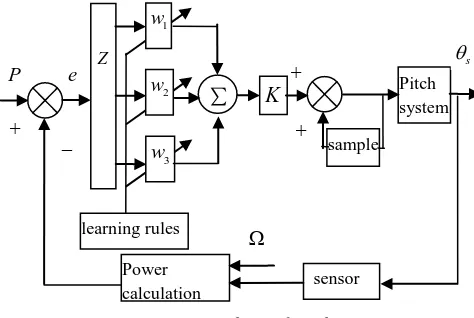
2.3.2 The PID controller of single neuron
The PID controller has the features of simple
structure and easy implement, but its parameters tuning is very complex. The PID controller
parameters are adaptively adjusted through
selecting the learning rules of single neuron to change the learning rate. The structure of single neuron adaptive PID controller for pitch system is
[image:3.612.68.305.467.626.2]shown in Figure 3. Z is the converter in Figure 3.
Figure 3: Structure Chart Of Single Neuron PID Controller For Pitch Static Load
Formula (6) expresses the control algorithm of single neuron adaptive PID controller in [9].
3 '
1
3 '
1
1 1 1
2 2 2
3 3 3
( ) ( 1) ( ) ( )
( ) ( ) / ( )
( ) ( 1) ( ) ( 1) ( )
( ) ( 1) ( ) ( 1) ( )
( ) ( 1) ( ) ( 1) ( )
i i i
i i i i
I
P
D
u k u k K w k x k
w k w k w k
w k w k z k u k x k
w k w k z k u k x k
w k w k z k u k x k
η η η
=
=
= − +
=
= − + −
= − + −
= − + −
∑
∑
(6)
Here,
1
2
2 3
( ) ( )
( ) ( ) ( 1)
( ) ( ) ( ) 2 ( 1) ( 2)
x k e k
x k e k e k
x k e k e k e k e k
=
= − −
= ∆ = − − + −
(7)
I
η is the learning rate of integral,ηP is the
learning rate of proportion,ηD is the learning rate
of differential,e k( ) is the deviation, u k( ) is the control output.
Selecting the Hebb algorithm as learning rule, and considering the relation among the weighting
coefficient w ki( ), neuronal input, output, and the
deviation, the weighting value can be adjusted like as Formula (8).
( 1) (1 ) ( ) ( ) ( ) ( )
i i i
w k+ = −c w k +ηe k u k x k (8)
Where c is the constant, 0≤ <c 1.
3.DYNAMIC LOAD CONTROL SYSTEM
OF BLADE
There is dynamic load component for the blade because that the blade is affected by turbulence, tower shadow, pitch, and other factors. To control
the dynamic load, Multi-blade coordinate
transformation theory is used. The rotating blade of periodic reference frame is transformed to the fixed reference frame by multi-blade conversion mapping mode. The stress analysis of blades is simplified due to eliminate the cycle property of blade in this paper.
Multi-blade coordinate transformation matrix is defined in [11],as follows:
1 2 3
1 2 3
1 1 1
3 3 3
2 2 2
sin ( ) sin ( ) sin ( )
3 3 3
2 2 2
cos ( ) cos ( ) cos ( )
3 3 3
P t t t
t t t
ψ ψ ψ
ψ ψ ψ
=
(9)
Where ψi is the azimuth of blade i.
Multi-blade coordinate transformation inverse matrix is defined in Formula (10).
Z
Power calculation
P e
learning rules
3
w
2
w
1
w
-+
∑
K
Pitchsystem
sample
sensor
s
θ
+
+
Ω
Controller Driver of generator
Mechanism of pitch
sensor Power
calculation P
-+
e
1 1 1
2 2
3 3
1 sin cos
1 sin cos
1 sin cos
P
ψ ψ
ψ ψ
ψ ψ
−
=
(10)
According to formula (9), the conversion relation between blade rotating coordinate frame and the wind wheel fixed coordinate frame is expressed as formula (11).
1 1
2 2
3 3
( ) ( )
( ) ( )
( ) ( )
g
z z
g
z z
g
z z
M t M t
M t P M t
M t
M t
= ⋅
(11)
Where i
z
M is the torque of blade flapping in the
rotating coordinate frame, i
g z
M is the parameter in
the fixed coordinate frame.
The research indicates that blade flapping
torque, blade tilting moment, and yawing moment in formula (11) should be expressed as formula (12) if the shear, tension and the torque at the hub center are ignored.
2
3
3 2
g tilt z g yaw z
M M
M M
=
(12)
Where Mtilt is the tilting torque at the blade root,
yaw
M is the yawing torque.
1 2 2
27 3 3
16 2 2
g g tilt c c c
R
M h x k h u
H
δ = − ⋅ − θ −
(13)
3 3
3 3
2 2
g g yaw c c
M k h u
δ = θ +
(14)
Where hc and kc are the gain coefficients, 27
16H is
the factor coefficient, R is the radius of wind
wheel,x1 is the top tower offset in the fore-and-aft
direction, x1 ⋅
is the vibration speed in the
fore-and-aft direction, g
i
θ is the pitch angle in the fixed
coordinate frame,δ is the increment, g
i
u is the
controlled variable.
The pitch angle is solved from equation (11) to equation (14) in the fixed coordinate frame, then
adopting multi-blade coordinate inverse
transformation, the pitch angle of fixed coordinate values are transformed into rotating coordinate values. The relation of pitch angle is expressed as equation (15).
1 1
1
2 2
3 3
( ) ( )
( ) . ( )
( ) ( )
g
g
g t t
t P t
t t
θ θ
θ θ
θ θ
−
=
(15)
Where θi is the pitch angle in the rotating
coordinate frame.
At this point, it has achieved the parameters
conversion between the rotating coordinate system and fixed coordinate system. The whole process for solving pitch angle dynamic component is more concise.
The actual adjustment value of pitch angle is got by adding static component to dynamic component of pitch angle.
4 . SIMULATION AND ANALYSIS OF
RESULTS
Bladed is a professional software package for
wind turbine, it has passed international
certification, and the software is widely used to design and analyze wind turbine. According to the suggested control strategies, designing external controller in the Bladed, then the data can be exchanged between external controller and internal
controller. Finally, comparing the control
performance between these controllers.
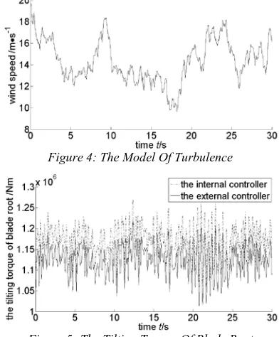
The simulation is realized by adopting the model of 2MW wind turbine of speed variable-pitch. The parameters include: radius of wind wheel is 40m, cut-in speed is 4m/s, cut-out speed is 25m/s, rated speed is 12m/s, air density is 1.225kg/m3, rated power is 2MW. According to the research focus, selecting three-dimensional turbulent wind as a wind model due to it includes the whole range, below the rated wind speed and above the rated wind speed.
[image:4.612.319.515.478.715.2]Figure 4: The Model Of Turbulence
Figure 6: The Flap-Wise Torque Of Blade
The Figure 5 has shown that the torque of blade root can be reduced effectively through adopting external controller in the whole range of moving wind speed. The Figure 6 has compared the variations and has indicated the flap-wise torque can be controlled effectively. External controller performance is better than the internal controller, then the blade load control strategies are authenticated strongly.
5.CONCLUSIONS
(1) The single neuron PID controller can achieve effective control for pitch static component.
(2) Using coordinate transformation theory can get the pitch angle for dynamic component, control process is simple, accurate, and reliable.
(3)The external controller has been compared to the internal controller, the external controller can effectively reduce the torque of blade root and blade tilting moment. The loads of these parts are reduced and the damage rate of unit is decreased, the service life of the wind turbine is improved. The control performance of external controller is more superior, therefore, the proposed control strategies are accurate.
ACKNOWLEDGEMENTS
This work was supported by doctoral seed fund of Chongqing university of posts and
telecommunications.
REFERENCES:
[1] M GEYLER, P CASELITZ, “Robust
multivariable pitch control design for load
reduction on large wind turbines”, Journal of
Solar Energy Engineering, Vol. 130, No. 1,
2008, pp. 1-12.
[2] A J EGGERS, JR R DIGUMARTHI, “Wind shear and turbulence effects on rotorfatigue and
loads control”, Journal of Solar Energy
Engineering, Vol. 125, No. 2, 2003, pp.
402-409.
[3] Yao Xingjia, Liu Yingming, Xing Zuoxia,et al., “Active vibration control strategy based on expert PID pitch control of variable speed wind
turbine”, Electrical Machines and Systems
International Conference, Oct. 17-20, 2008, pp.635-639.
[4] B.Boukhezzar, L.Lupu, H.Siguerdidjane,
M.Hand.“Multivariable control strategy for
variable speed, variable pitch wind turbines”,
Renewable Energy, Vol. 32, No. 8, 2007, pp. 1273-1287.
[5] K.Selvam, S.Kanev, J.W.Wingerden, et al., “Feedback-feedforward individual pitch control for wind turbine load reduction”.
International Journal of Robust and Nonlinear Control, Vol. 19, No. 1, 2008, pp. 72-91.
[6] S. M. Muyeen,Rion Takahashi, Mohd. Hasan
Ali, et al.“Transient stability augmentation of
power system includeing wind farms by using
ECS”, IEEE Transactions on Power Systems,
Vol.23, No. 3, 2008, pp. 1179-1187.
[7] Whei-Min Lin, Chih-Ming Hong, “A new elman neural network-based control algorithm for adjustable-pitch variable-speed wind-energy
conversion systems”, IEEE Transactions on
Power Electromics, Vol. 26, No. 2, 2011, pp. 473-481.
[8] E. B. Muhando, T. Senjyu, A. Yona, et al., “Disturbance rejection by dual pitch control and self-tuning regulator for wind turbine generator parametric uncertainty
compensation”, IET Control Theory, Vol. 1,
No. 5, 2007, pp. 1431-1440.
[9] He Ping, Wang Kewen, Tse Chitong, “Studies of the improvement of probabilistic PSSs by
using the single neuron model”, Electrical
Power and Energy Systems, Vol. 29, No. 3, pp. 217-221.
[10] M. Zaheer-uddin, N. Tudoroiu, “Neuro-PID tracking control of a discharge air temperature
system”, Energy Conversion and Management,
Vol. 45, No. 15-16, 2004, pp. 2405-2415.
[11] Sven Creutz Thomsen,Henrik Niemann, Niels