The Rate of Solution of Methane and Propane
in Hydrocarbon
Oil~Thesis by
Earl
S. Hill
In Partial Fulfillment of the
Requirements for the Degree of Doctor
of Philosophy
California Institute of Technology
Pasadena, California
Contents
Page Introduction
--- l
Materials
---
4Apparatus and Methods --- l l 'Methane
---~---
25Santa F'e Springs, Calif. natural gas --- 28
:Methane Solutions --- 4·a Methane Diffusion --- 56
Diffusion Constant-Viscosity-Temperature Relation --- 60
Table I
---~---
61Table II --- 64
Table III
--·---~---·---
65Propane --- 66
Table IV ---·---·---•·-- 96
Effect of Liquid J!!xpansion on Diffusion --- 97
Acknowledgements
---115
Summary ---~---~-~--~-------"------116
References ---117 Appendix I
THE RATE OF
.
SOLUTI
ON
OF
METHAi.~AND PROPA1'1'E
IN HYDROC.ARJ30N OILS
For many years after its first commercial success in 1912
repressuring of oil formations with natural gas has been Considered
and used. At first its use was confined to stripper wells in fields
from which the gas pressure had reached an advanced stage of depletion.
In more recent years repressuring has been applied early in the lives
of some fields to maintain the pressure. Instead of allowing the gas
to waste, the pressure to fall off, and the production to decline
rapidly with increasing unit production costs, it has been found that
the surplus gas in the flush stages of a field can be returned to the
ground with manifold advantages. The Sugarland, Texas, field, operated
by the Humble Oil and Refining Company» is a notable example of this
kind of repressuring, or pressure maintenance. Repressuring begun
several years after discovery has made the drilling of many wells
unnecessary, has conserved gas and gas pressure, has kept the wells
flowing, and has made the recovery costs notably cheap. Storage of
natural gas in depleted formations has become a factor in natural
gas distribution from producing fields because it provides a cheap
storage space, produces a wet gas from a dry gas, and increases the
oil recovery from the formation.
An investigation of the literature shows very little data
which can be used to calculate the quantities of gas, pressure, and
the number of wells required to develop a field with gas
repressur-ing methods. Much of the development has been that of purnping the
gas into the formation and finding out what happened in the formation
2.
the input and in surrounding wells, and the effect on prqduction.
This is an unsatisfactory method as shov;n by the fact that the
pro-cess has been unsucpro-cessful in a ni.unber of applications. These
un-certain conditions indicate that an investigation of the fundarnentals
involved is necessaxy. For this purpose an investigation of the time
required for natural gas to dissolve in petroleum oils in formations
was begun as a part of .American Petroleum Institute Research Project
Nu...~ber
37
in1927.
This investigation has pro§ressed continuouslysince that time to the present in the hands of several investigators.
The problem has resolved itself into several sections which can be
classified into two principal divisions; fundamental laws of diffusion
of natural gas in oil and oil-filled sands, and the determination and
application of the physical constants for these laws.
The fundamental diffusion equation explaining the rate of
solution process has been investigated by the previous investigators,
Pomeroy, Scudder, and Stapp(1•2
•3)
and a satisfactory equation foundto fit the cases for which their assumptions apply. Reference should
be made to their paper and to Pomeroy•s and Stapp1s theses(l,2) for a
derivation of the equations described below and for a description of
the general methods of making the determinations. It has been shown
that the Fick proposition is valid with certain limiting assumptions
for this work. This proposition may be stated in the following
equation:
2.3-
-DA~a
t
-
a
x
where q = quantity of solute which has passed a given point
c = concentration
x
=
distance in direction of flowt = time
D =diffusion constant in sq.cm./sec. or sq.ft./b:r.
C = concentration at infinite time s
~.
Solution of this equation for the case of a liquid column
of infinite depth gave the following result for the quantity of das dissolved:
Q,
=
2C A sY
rot
T
It has been shown(2
,3)
that for most practical purposes this is theonly solution that will need to be considered in the determination of
the physical constants involved.
The limiting assumptions in obtaining this equation for the rate of solution are as follows: {a) the diffusion constant
does not change with the concentration of the solution; (b) the
layer immediately under the surface film does not retard the passage of gas into the liquid; {c) the gas moves through the liquid only by diffusion.
The deter~ination of the physical constants for the rate of
solution equation involves the determination for each gas present in
natural gas in appreciable quantities in a series of oils covering
the range that may be met in the fields. This study should cover
4.
conditions. This thesis is confined chiefly to the determination
of the physical constants; namely, the diffusion constant and the
final concentration value, together with other required data such
as viscosity of the oils, gas compressibilities, and expansion of
the liquid upon solution of gas, for methane and propane. In these
determinations it was found that at least two of the limiting
assump-tions involved in the original equation were not fully complied with
in the case of propane; namely, that the diffusion constant is not
independent of the concentration, and that expansion of the liquid
on dissolving the more soluble gases causes movement of gas other
than that by diffusion.
An
attempt has been made to devise meansof evaluating the results of these effects.
Materials
The methane used for the studies that were made to
deter-mine the effect of temperature on the diffusion constant of methane
was prepared by the same method as that used by Pomeroy, Scudder,
and Stapp with some modifications of the apparatus to give more
re-producible results. However, the purity of this methane was not
ex-ceptionally good. The ethane content was approximately
1.5%
but thenitrogen content was UlLk:nown and not negligible as supposed at the
time. The natural gas used for the preparation of this methane was
obtained in the Santa Fe Springs field from a gas-lift compressor
plant on the Walker lease of the Standard Gasoline Company. All ethane
5.
The methane used for the runs at high pressures was
pre-pared from city gas in the same Wa;f as that used for the temperature
measurements but in a larger setup described by Kircher. <
4)
This gascontained
0.98%
ethane and the air content was calculated to be3.2%
from the gas density obtained with an Edwards gas density balance.
The methane used for all the final determinations at
30°0
was prepared from city gas by a process which removed most of the air
as well as the ethane and heavier. The ethane and heavier constituents
were removed by activated charcoal as before but with better results.
The final ethane present being
0.36%.
After treatment with charcoalthe gas was passed thru a steel bomb surrounded by liquid air; the
pressure inside the bomb was maintained at 40 mm. or less. At this
temperature and pressure methane is a solid and drops out of the gas
stream. At higher pressures the apparatus freezes up, and at lower
pressures the capacity of the vacuum pumps is reduced and the loss of
methane is greater. Methane solidifies at
89°0
absolute. The vaporpressure of the solid is about 20 mm. at liquid air temperatures,
de-pending somewhat on the composition of the cooling medium. Ey this
method the solid methane is condensed in a gas space where the nitrogen
present is small and the degree of separation ought to be good.
Un-fortunately the laboratory assistant responsible for analysis of the
methane for air content has not yet been able to get reproducible
results on methane of this purity. This methane certainly contains
only a small fraction of the impurities that were in the methane used
b.
No additional work has been done with ethane because the
experience with propane indicates that the quantity of impurities
present in the
96.5%
ethane available would cause a large divergenceof the final concentration value from that for pure ethane.
The propane was obtained in a sui'ficiently large quantity
from the Standard Gasoline Company. It was supposed to be
99%
pro-pane but after a number of runs were made it was suspected that the
quantity of impurities present was larger. A fractionation analysis
showed
4.03%
ethane,93.20%
propane, and2.77%
isobuta.ne. Figure33
showing the curve of experimental data for the rate of solution of
commercial propane in kerosene shows the effect of changing
composi-tion of gas in the gas phase in the tank. The gas for these two runs
came from the same tank with possibly a twentieth of the total quantity
present being removed between the two runs, which were made at the
srune temperature and pressure with the same oil. This divergence due
to changing gas composition is too large to permit even approximate
determinations. If the tank had been inverted and the propane
with-drawn from the liquid phase, this change in composition would not have
been apparent until a large arnount of the material had been used and
possibly all of the data on propane would have been erroneous.
The coI!lmercial propane was redistilled in a glass still at
dry ice temperatures. The still consisted of a kettle, a column one
inch in diameter and ten feet long packed with glass rings, and a steel
condenser bomb. Acetone cooled with solid carbon dioxide was used to
obtain the low temperatures for the distillation, to obtain reflux at
one-7.
half liter Dewar tubes were used as containers for the cooling mediu.~.
It was found that materially higher rates of condensation could be
ob-tained in the final condenser, with resulting lower pressure on the
column, b~ using acetone, as compared with natural gasoline. This
was due to the lower viscosity of the cold acetone mixture with less
foaming when carbon dioxide gas was evolved. Commercial acetone was
found too corrosive and unpleasant to handle since the frothing
fre-quently caused it to get on the hands and clothing of the operator.
Distillation in a glass still having a packed column two feet long,
with sodium hydroxide, reduced the corrosive action on the steel parts
of the apparatus.
The kettle of the propane still had an 800 cc. capacity, an
inlet tube sealed to the bottom, and an internal electric heater. It
was cooled by the cooling fluid in a Dewar tube. The inlet tube was
brought u:p the outside of the kettle within the Dewar tube and out to
a stop-cock. Since the propane was condensed into the kettle from the
steel tanks in which it was stored as a liquid at room temperatures,
it was desirable to have this type of a connection to fill the kettle
in a reasonab.le length of time without running up the pressure in the
glass apparatus.
The column was heat insulated with ordinary steam pipe
lagging. This lagging is none too satisfactory to use for any length
of time, unless the covering is made air-tight, because moisture from
the atmosphere condenses on i t next to the cold column and eventually
wets the lagging so that it loses its heat insulating properties. The
8.
which cold acetone was circulated. Since the column was vertical, the
circulation, after once being started, was automatic due to the
evolu-tion of dissolved carbon dioxide gas when the fluid was warmed in the
reflux condenser, producing a gas-lift pumping action. This method of
circulating the condenser fluid at a rate dependent on the amount of
heat to be removed is not entirely satisfactory unless precautions are
taken to carefully heat-insulate the tube connecting the container,
where the solid carbon dioxide is added, with the bottom of the reflux
condenser.
The progress of the distillation was followed by means of a
mercury mp..nometer; thermocouples placed in the head of the column, in
the inlet and outlet of the reflux condenser, in the kettle, and in the
final condenser bath; and an illuminated window near each end of the
colunm. The distillation was carried out in 300-cc. batches. The
first portion of the gas coming over was blown off, consisting of
ethane and propane. Since ethane cannot be refluxed with solid carbon
dioxide at the pressures that can be used in glass apparatus, this loss
of propane could not be prevented. After the ethane was removed, the
pressure could be lowered to
350
to400
mm. where the distillation wascontinued. The rate of condensation in the steel bomb used for the
final condenser was the controlling factor in the rate of distillation
except at the beginning. When the column began to prime at the bottom,
the rate of distillation was slowed down until the reflux drained down
to the kettle. This occurred only during the beginning of the
distil-lation,r;hen the rate of condensation in the final condenser was highest.
9.
the valve connecting it to the column was closed and another opened
to a steel storage tank. The cold acetone on the condenser bomb was
then removed and replaced by hot water and the propane distilled into
the storage tank.
The final analysis of the product by fractionation showed
99.2%
propane and 0.3% isobutane. This method of analysis tends togive high values for a heavier gas present in quite small amounts in
a lighter gas, so the purity was believed to be satisfactory.
The gas used in the two natural gas runs was obtained in
September,
1931,
from the Standard Gasoline Company property in theSanta Fe Springs field. The fractionation analysis gave the
follow-ing results: 87.23% methane, 7.96% ethane, and 4.76% propane.
How-ever, since the gas was drawn at 20°C thru a 40-foot line from the tank
at a pressure of 700 lbs. per sq.in., it may have been somewhat dryer
when it reached the reservoir of the rate of solution apparatus. The
exact composition of this gas was immaterial since the runs were only
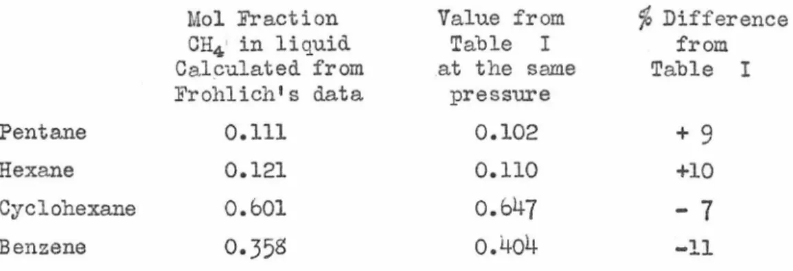
preliminary in order to find out how a mixed gas would behave in the apparatus. The oils used for the determinations consisted of pure
individual liquids, refined oils, and crudes. The physical constants
are given in Table I. Isopentane and pentane were obtained from the
Philgas Company. The isopentane analysis was: n-butane 0.20%,
isopentane 99.73%, and n-pentane 0.07%. The pentane was specified as
C.P. and_ its purity probably approaches that of the isopent.ane. n-Hexane,
cyclohexane, benzene, n-pentane, and 2, 2,4-trimetbylpentane were
obtain-from the Eastman Kodak Company, and all had a satisfactory purity except
10.
was a heavier oil. Nine-tenths of the liquid distilled between
67.8 and 70.3°0 and the end point was 77.2°c. The oil should have
had a 1 oC boiling range. The benzene was thiophene free. The
cyclo-hexane had been purified by fractional crystallization. The n-heptane
and 2,2,4-trimethylpentane had o.3°c boiling ranges. The kerosene
was purchased from the Shell Oil Company; it was water white when
re-ceived but after two years it had precipitated some solid and changed
color. The spray oil supplied by the Union Oil CompaD.y was stable and
did not change its physical appearance. The petrolatum was a water
white medicinal oil sold by the Sterling Laboratories. The crudes came
from the following sources:
:Bradford, Pa.
Smackover, Ark.
:Bartlesville, Okla
Lima, Ohio
Sugarland, Texas
Ventura, Calif.
Rosecrans, Calif.
from
II II II II II
II
Forest Oil Co.
Standard Oil Co. of Louisiana
U. S .:Bureau of Mines, :Bartlesville.
Ohio Oil Co.
Humble Oil and Refining Company.
Gosnell Lease of Sheal Oil Co.
Union Oil Company's Chandler No. 3
in the Rosecrans District from the
11.
Apparatus and Methods
Altho the general method of making the determinations has
been described before, a number of changes have been made since the
description was made by Stapp. (l) The flow sheet (Figure 1) shows the
connections used. A gauge equipped with a stainless steel tube was used
gor the reservoir instead of the old multi-tube bronze gauge. A refill
valve was added so that the reservoir could be refilled during a
deter-mination. A special, fine-lined, uniformly graduated scale was placed
on the reservoir gauge instead of the original test gauge scale. This
materially improved the accuracy of the reservoir readings. The
reser-voir tube was found to check between successive calibrations within
about
1/4%.
The test gauge used to measure the pressure of thedeter-mination was removed from the absorption cell head and placed on the
gas inlet line between the control valve and the flexible coil. A
lOx magnifier was supported from a hole in the center of the test gauge
glass malcing it possible to reproduce a setting to ±0.1 lb./sq.in. as
read on the gauge. A valve was added to the inlet line so that the
absorption cell system could be evacuated when desired, and the test
gauge calibrated at the end of a determination without removing it from
the apparatus. The line leading to the gauge tester was approximately
40
feet long and23
feet in elevation above the tester, and consistedof
3/16
inch copper tubing with a small boiler water-column near thetester. Connections were made directly to the gauge glass holders on
this boiler water-column and the valves at the top and bottom closed
so that gas and oil were admitted to the gauge glass section only.
12.
was connected to a gauge tester and a gas line from the apparatus to
the top. In order to check the gauge, the gas line was filled up to
as nearly as possible the same pressure as the determination with gas
from a nitrogen tank before the valve to the apparatus was opened. A
5-foot mercury manometer attached to this line was used to give the
zero reading of the tester and for calibration up to 25 pounds gauge.
Correction for the weights of' the gas column to the gauge tester was
made on the readings.
A low pressure regulator was placed in the vacuum line to
control the low pressure required in evacuating the air from the oil.
The syste~as developed on another .American Petroleum Institute project
for vacuum distillation control and found quite satisfactory. (5) In
connection with this a trap was designed so that the cooled part could
be easily removed and weighed to determine the loss of oil from the cell
during the long evacuation. S.A.E. brass flared fittings were used with
copper tubing for the connections to the trap and found to be superior
to any known ground glass or rubber tubing method of connection. The
quantity of oil pumped over into this trap was seldom more than 0.1% of
the total in any of the cases where the method was used.
The change in volume tube was substantially the same as
for-merly except that the use of slightly heavier glass and longer a.1111ealing
times (8 to 10 hours) permitted pressures twice as great to be used so
that the expansion in liquid volume could be determined at the same
pres-sure as that used in the determination up to about 305 lbs./sq.in. This
tube was surrounded by a suitable guard and attached to the apparatus as
13.
The accuracy was materially improved by better technic and the
sub-stitution of 1/811 O.D. copper tubing for the rubber hose formerly
used to connect it to the apparatus.
A new calibrating burette was designed and built (Figure
5).
It had two bulbs,
5
cc. and25
cc., so that any irregular portion ofthe reservoir calibration could be followed closely. A gravity return
of the mercury to the upper position by setting the leveling bottle on
a stand and allowing the mercury to flow into the burette was
substi-tuted for the former method of blowing it back with air pressure.
Sliders with a fine wire indicator were placed on the meter stick
be-tween the burette and its manometer so that the mercury level could be
easily read to 0.1 rmn. This burette requires one-half the time for a
reading of equivalent accuracy compared with the former burette. It
was opetated so that readings were taken at constant pressure making
it unnecessary to correct for the 1/811 O.D. copper tubing used to
con-nect it to the apparatus.
The absorption cell was removed from the former rigid support
and placed in a weighted, triangular support mounted on rubber stoppers
four high (Figure
6).
This was found desirable due to vibration ofthe building and the ~armer support. The weight of this system was
about
30
lbs. for the brass cell and50
lbs. for the steel cell. Indetermining the final concentration value the absorption cell was placed
in a shaker operated from outside the thermostat, instead of using the
hand to hold the cell and shake it inside the thermostat as formerly.
This eliminated temperature disturbance due to heating or cooling the
approxi-14.
mately three times the area of the old brass cell to give sufficiently
high rates of flow for accurate measurements on oils with a low
diffusion constant and fof oil sands. This cell was designed to
operate at pressures up to 3000 lbs. per sq.in. so that it could be
used with the other high pressure apparatus of the project. Also it
will enable the use of high pressures in obtaining uniform sand
porosities in an unconsolidated sand when pressing a sample into the
cell. The drawing of the steel cell shows the construction features.
The head. was designed to avoid dead gas space with the blowoff plug
having an extension that nearly fills up the hole that leads up to it.
The size of the gasket on this cell was cut down to a fraction of the
sise used in the older cells. For very high rates of solution the
ac-curacy of the reservoir system is impaired and larger quantities of
materials are used than are necessary. Hence, two brass
slug~s
weremade with different sized stems to place in the brass cell to cut down
the cross section area and the total volume {Figure
3).
~he small endof one of the slugs shown in Figure
3
was placed in the bottom of thecell and the liquid level maintained as near the bottom of the large
portion of the slugs as feasible. By this combination of cells and
slugs, and a slug in the bottom of the reservoir, the reservoir was
operated over a far more accurate range than was formerly possible in
many cases. The liquid level was placed as close to the top of the cell
as possible without seriously interfering with the determination of a
final concentration value.
The photographs show the apparatus setup for various
15.
location of the gauges inside. A chart used to enable the operator
to read the reservoir accurately to
0.1°
on the scale is shown justto the right of the window. Figure
5
shows the front removed and thecalibrating burette in place. The calibration is, of course, done
with the front on the thermostat as is the case for all the other
de-terminations. Figure
6
shows how the apparatus is connected up for a rate of solution determination with the cell and its support in theleft end of the thermostat. The fourth view (Figure
7)
shows the change in volume tube in place for a determination. The connectionfor the absorption cell is blanked off dur~ng this operation and the same gauge used to determine the equilibrium pressure. In this
photo-graph the absorption cell has been placed in the shaker for an
equili-brium determination.
Figure 8 shows the supporting frame and one of the Ostwald
type of viscometers used to measure the viscosity of the original oils.
A quartz instrument having a water time of
530
seconds at30°c
was usedas a cali"brating standard and for the determination of the viscosities
of the lighter oils where it was thought desirable to make the
deter-minations. A pyrex instrument with a water time of
94.3
sec. at45°C
was used for measuring the viscosity of the heavier oils. This
instru-ment was calibrated with kerosene measured in the quartz instruinstru-ment
be-cause the water time was too short to avoid uurbulence. Such a
combi-nation of different sized capillaries gave viscosity measurements
accu-rate to
0.5%.
The small bottles on the right side of the viscometerwere partially filled with liquid of the same composition as that in
16.
to force the oil up into the small bulb on the left arm of the
in-strument from which it flowed thru the submerged capillary into the
large bulb on the right arm at a rate depending on the viscosity.
Short times were measured with a chronogTaph driven
by
a synchronousmotor. This chronograph was used to calibrate a stop-watch for the
longer times beyond the range of the chronograph.
The thermostat itself was completely rewired and all
neces-sary controls designed and placed in position so that the temperature
control and other electrical parts of the apparatus were operated with
very little trouble and few changes over a period of more than two years.
The density of the oils was determined by weighing the oil
in a calibrated pycnometer.
The average molecular weights of the crudes, kerosene,
spr~ oil, and petrolatum were determined by the freezing-point
Con
fro
I
Vo
Ive
Goge
.showin9
pres$vre
of
determination
LifVt<I
Absorpt'"lon
cell
Der
lee
to;-/'1ercury
_
>
l'nC1no
merer
A
e..se
rvoi
r
!JUj'e
L_
_______
_
Low
Ca!i6n::T
f
lnJI
Solie/
Ct1r/Jo11
cliOX
iQ'e
trt1p
pressure rej>ulo
/-or
Vqcv~m pvmp
Gos
$Uf'p/y TOI'"tht'
dererm- lno
rion
~---)(
~
Nt't-ro_yen 'funk
Chon,je
117
Volt.1me
tv
6'e
~:1
0;/
t'r1p
Gq.9e
I
)(
I
I
rest-er
Appt1rtltUS
for
the
!1edsurement
of
Ille
/?,ate
of
Solvtion
Fig.
I
T/Jrd for
std.
f
i/ting
Copper
qosket"
Solder gas /ref'
K
i . . : : - - 2L --+---~
"'
1-=--~~
'1.1=--:-
~.
r= _--
-=--i I --.:.:::J
'-=-=
=-1 I I I ,, I---=
--l1-: - -==-t I 7!f t--
----1
~==~:
~~~~~
I
.
1
t-,:J--=~=i
~2° -~-)
I
I
I:
I
i-f'
L
I
I
L _____ _
Steel Cell
18
6
nickel steel
19
Cell Slugs
T
. - - - r
- - -
--F'
- - < I - - + + - + - - -
---I----24"" - -..
!io'IE--~
-/~11
~,,
Steel Drill l?od
Brass
\
3 II
T;l
FIGURE 4
Front of Thermostat
FIGURE 5
Calibrating Burette
II
,
:nBURE 6
Absorption Cell
22
I
\
23
..
:l~i-.
-
: ~ \.
.
- r t ,!-] · - •
.
'~\~
~.~'
·:.·
~
~
' '
FIGURE
'I24
-~
-FIGURE 8
25.
Methane
The rates of solution of methane in seventeen oils were
measured at
30°c (S6°F)
and at two or three higher temperatures forfour of these oils. This data is given in Tables I and II and the
plots of the volume of gas admitted to the cell versus the square
root of the time are given in Figures
9 - 30.
The run numbers givenin the table are the same as those used in the original notes, while
the oil or point numbers have been used to identify the points on
Figures
27 - 32.
The data for Figures9
-
30
were originally plottedon a scale three times as large as that used for the figm·es. This
was necessary to obtain a reasonable accuracy in locating the lines
through the points.
Measurements were made not only of the rate of solution, but
also of the final concentration value, the increase in liquid volume
upon solution of gas, and the viscosity of the original oil.
The measurements for runs
136 -
160 and 0-20 to 25 were madewith the purest methane prepared. The plots of experimental data
show-ing the volume equivalent versus the square root of the time will not
be discussed individually as in previous theses because the methods of
operating the apparatus were standardized to such an extent that there
was little variation. An occasional variation is found such as the
peculiar curvature at the beginnings of Runs 138 and
144.
This isprobably due to faulty control valve opening at the beginning of the
run, permitting the gas to be admitted too rapidly. However, this is
of small importance because the points before the end of the first
26.
such as in 137, 144, 152 are due again to irregular opening of the
control valve, or missing a reading, causing a greater pressure variation
than that used for the other parts of the run. Check runs have
con-sistently shown this variation to have no appreciable effect on the
slope, altho it is undesirable. A column in the table is designated
11cell11 because the cross-section area used in all the runs is not the
same. The area of cell B was
9.935
cm~ at30°c.
For cell B with ssslug, the area was
9.s91
cm~ In cell S the area was31.467
cm~ Thedeterminations made on the same oil with different cell areas gave the
same diffusion constant as shown by
148, 157,
and by155, 156.
Severalruns with spray oil in B did not check
153, 159,
but the slope was solow that it could not be determined very accurately. Furthermore, the
reservoir gauge was erratic during these runs, and faiied at the
soldered point where the cap is screwed on the end of the tube during
the last of this group of runs not reported. Run
133
was made with agas whose nitrogen content is uncertain; altho reported as 2%, it was
probably considerably less. This run and
139
were made with the airevacuated from the cell and the oil. The variation from the
determi-nations made with one atmosphere of air in the cell and oil is within
the experimental error. This is quite fortunate because the removal
of the dissolved air from the crudes without changing their composition
would have required an extensive setup. The fact that the air is not
removed from the system introduces an error which could not be neglected
if the apparatus were designed to give a high degree of accuracy.
The expa.~sion of the liquid due to the solution of gas was
percent increase in volume. From this data and the final equilibriurn
concentration the value
6
1.was calculated for the apparent increase involume of the oil for each unit volume' of gas dissolved. Following this
of
the true value 6 was calculated. The apparent value is used to correct
the apparent concentration to obtain the value of S which is the
equi-libriurn quantity of gas dissolved in a unit volume of original oil.
Dividing this by the final solution volume gives C which is the
equili-s
brium quantity of gas dissolved in a unit volume of solution. The gas
volumes were calculated for 30°c and one atmosphere in the experimental
work and corrected to 6o°F and 30 inches of mercury for the final values.
From the corrected slope of the line of the quantity of gas
admitted to the cell versus the square root of the time and the
equi-libri-urn concentration C the diffusion constant was calculated as
s
follows:
D
=
k(~)2Cs
where k contains the area of the oil surface and other constants. At
30°c it has the following values: for the B cell, 1.3262 x 10-
4;
-
4
-4
-l~for Bss' 1.3380 x 10 ; for B
15, 5.392 x 10 ; and for S, 0.13220 x 10 •
This method of calculating and. correcting the various factors has been
completely described by Pomeroy(2,3). A
sa~ple
of the calculation ofan isopentane run is given in the Appendix.
The experimental data for runs 57 - 62 and C-7 to C-17 (see
Figures 18 - 23) were obtained with the older methane which contained
a higher nitrogen content. These data are, of course, not as good for
this reason and also because the apparatus was not as reliable as it
was at a later date when the 30°C determinations were made. However,
2$.
effect of increased temperature on the diffusion constant of methane.
up to
6o
0c.
Figui·e 24 shows runs $7 and 8$ made at 2000 lbs. per sq.in.
with the assistance of the solubility apparatus described by
B.H.Sage~b)
This work was preliminary in order to find out whether any large varia~
tion in diffusion constant would be found with the use of high pressures. The results indicate some increase in the diffusion constant with
pres-sure, but the change is small compared to that in the case of propane, as will be shown later.
Figure
25
is a plot of two runs made with Santa Fe Springsdry natural gas. These curves have a definite curvature at the begin-ning that extends well beyond the usual disturbances at the beginbegin-ning
of a run. After a time the rate settles down to the straight line
relation. The curvature is due to the higher rate of solution of the ethane and propane in the gas causing them to be depleted in the gas space. During this depletion the composition of the gas in the space over the oil is changing to a different composition from that being admitted to the cell. This change continues to take place until an equilibrium is reached, so that the gas going into solution has the same composition as that of the gas being admitted to the cell. The diffusion constant for this dry natural gas after the rate had settled
down to a regulax square root relation is about 10% greater than that
for pl1.re methane. Some preliminary calculations on the probable rates
29.
pressure. The composition of the gas over the oil will be very low
in propane. This is due to the widely different solubilities of
methane and propane.
Figure
26
is the plot of temperature versus viscosity usedto obtain the
6o°C
values for Rosecrans and Bradford crudes. This wasnecessary because the change in composition of the crudes at this
tem-perature was so rapid, in spite of the vapor bottles, that a value
± w : : : : L . _ ' ~. -._l=c:J+l ... ;.;::--.. _·•.·.-.:_.: : ... :: -_·. ·:, : .. : . ...:.--: _'. .... ·.·,·_J·=:_-__ :.-.: ·t _;.-=-_: 7+...:..·i..c. ~_:.:c_-:..:. .... ~ --.;-.... -·-·L -.-•. J '~,' ... +,.. " ... ·
1::f~x ::J-;
illJ
! tj
=if-!:
fil] :Hi• ... p::-~ · :.T, , µ::;:::::: - .... - +!-' - -- ~ .,.,.... :p+::c:=:... .. ,~±j:.::w. i-''f ·t+t-=R+F :~.:.r:_r:rl1 t::r+
*
•iti rt-t+f
ffl
+ I- + ' -+
·r
,.
-rr·
,
,
+
1:I- -1- ~ ".
H
I+-!--[j::j- :+ ti ·~- H
-i:l:t ++ .. . 411 .
'
j:j: ·iht•, ·t-ttt-tti-rrttt1·_++,.,_-_ :f:E:,f1,ff_ .. !-· r:J_,.::.j:. -_i,=.=f+=t-t~.flil+ .. :"+.,+' HI···· i·J . '+,' , ' .,, +H
t1 l=ttf1r:.f+t1,...r+,
mm
'
'
'
~
'E]
: j T jj: Hm
f-~
H w ' :i=+~
WI
~tEI
!
:lt
m.
~-·~ - H-f -~i -[:.R=l .. '. : :j:~ TB±.· , . . l:j::i-1
:-Iii=
r.:l:.h+it~~~ -!-l-l- , l-l-1+++. _l-++•++-+++++++<J1++-+++r+++;+··.,. ++-rr++;++1++·+, 1:H·tl::j_j:~+
+l~ -·~ lo+ 'ITT ~:)- . +. ·+f:r i:J:j:l:J±j~ r::j:H'-Tff-+IW~ :+-1-. 1-l + "-'-1· ~ti U i~f-titj: :t;:· . '
1_' Hf. "'""~J[TTTT'" '-'++-t+;h-l I I+ ++ rh i±l-J::
+r+J-
-rr
·
-+
~. :,+-;-;-, t ~ :Ii. '_.:t-:r-µ
Y~ -r-r +- I- + ·--t-i-r+
~r:rtl 1m r-rt-i- I+t-++
-rr~ ~.+-+
-L+t-+1-- -L+t-+1--trr
t-:m
'S'
±!-.
H'ff
• 1. -
• T ~ ~· _
1 1-·=t£i-ni
, .-tt-H-Hf-t-+t
1
1···1
1;!·1·:
;_j,1
I :;;
I
l Tf T ff fl 1-H-t I ! ; -~·--1+'-H+ h ··!-'-I•·~
r1t~tH:
'.:t
r! t-( t ~ }t -~ q ! : ; ~ ~::~ ' r-~
~1t
1
iww
mr
-m=1!
11m
~
a1
wm
m~
~~
f-oo
™
ii
mmrwm
w
1
mmm
~
oo
1
r:r:~
1J
m
i:
~
m
oo
1
n~r-m
woo
m
~
m
m
1
w
m
1
f ;n
1
h~t
1.-.
t±
l-+l--4--1-J---4+-l-1t~~=
:~k
:c~.w11mrwmm
1
~
1
nooM#ttfWJ!filt
l
imat~m
1m
w
r
w0011m
ru
11
1ttt
1
Jumwt~~F~
Lt-. · 1 ., , +; J_ -~ -•• LJ_ -L'-l--! m ~· ~'-'--l 1' 'fI
;~ml. -c, -c. -H+ +c-·. ~t" r f-t t_! I Lt-!' I.; [ • LJ+iHI
'·.-:-'
-'-_ !-+,,er!-. 1:.J+-~ .;.:t,. +rt-1ri+
1-~c~ :t:r;:J _ :t r::i+ H: -~f: 1 :-r: ~ ' · ~;.-,= H~ ITI ' -l
j, .• 1:1 ''I . -lkl-f l -i.~ --~J
IB- +<-"+-· , t-@1:-1+1-+-:r::r:.1-i-r·FF.t~ M Wf1·-Ei·filj'·
''rr+J# 1 i--J_ b' '-Lllrt~.'1'-i-rll--L·, !-' 1rr'. 1 1, 1 i tn . "'""""
-l
j-._._
j_\ ~J_J .; I ·! ~--l-·_i -: -t-:H-1--. I - -t-H·rr-r{J-- ·- ---:fl=G~Tro::-::-tr:r-~ ·l='r-. ;, __ j:=~ :ti-- 1~-- 1~1-i-:·.~ w ~ · ~ H-:·, .. ;·: ·~:=1 ·:-t:..' -1 ~ .. i. ~!1-1 --1-· L"I:! .' :L :t:S '-, ~-··; J. ! 1 '1tlf
~
- 1-,-,->FR-~=Jff:!: ft --H-i=r+Pi$$
.
-,
+--1-1---,~ 1 Ult h-r '!-I-!
c~t=l: ! , ,--, -~11-, -~ , i)' H -,:~j=t-~f · t I h il-h I!-!' . Irr 1 I J i 'i: >•Ir
I.
··
·'
1.'l' '. · t:--tt J i'll
:J:H--'tl:
i·H-_f_t, i-t-1--.-:j: -++-l-l---lim±±J+-H-r--f-!-i···-~+'-.-l-':}-1.+ ;mu f-'-r: • rL } 1-•-,--1 1+ H +!.tr f-f 1mJ l--' 'j ·-1t'rf~n i:iL'l i ·'r'l ·-''.1 i'·i+1t• [Ht' 1111 t-'·li· o 1_1 1· ·-1 ~.-u11 1 1 .1 11·· ·Jl _:_-1: 1-_ ::r=i= --+H+ i:!=Fr ,_ .m+:q:c'.-li--tj:tttJ cT' · i l ft+ .:!=t:~l 1 -r:rµ-+ 1+ ti= r. f l r+~c-cL ., : u:+.T{-t' ,,_, ·11
·,~:p Tli~ pi:, ctl J l 1 ;.'., 1 'I' 1, ,1.1 ,1 _,::t. :---t:r,f + ·:, :tt1--.. "W+Ll-1 LHl --:-+;..-J: .. " i l rl• q:,., f-ijTf1l-r-, ,r-f'. -1t1tr ,-ll'i l '-1 i:i:r-·1 1itl·r-:H+H-1: .; ~1··-rl1'
1. • • H. ~1 i. · 1 -. · 1-+.+ - I-rt± rn:.· 1.· rt++&'
±I. --rt -r::;: r ~ . ,-: -. .+t::J:. ·tH+ 1-· . r --~ , ;-.lll
+ d t· I.I
rtd t · 11 1.- ·-i 1-'. f-, f. f-. '. E [L.+µ. 1 -H+ ' -1 -.-·. 7 ·1 1 fl : n, rt-1 1 -d • J +t: 1 1---. ++ "H_-.. r+t-H:-:p::;+ ,:::.:_, /<"' .: '-:::J-, i=f:i::c ::tp !:trr ·, > " -' _ tj: t ·'t'r~ :::1 -.-~ • . ,--1 ,,+ '.' :1 i •;·rr ,_,., 1 •• _ r: i '.---•r I 1 1 ! 1 . · I .. I· f . i I I '--! jl 1 -H , " i:l±Lr . ..:..w+ -!+H-'-t+' -'o,; -/' i+I -+-I= -;-r!-r J--.. !:u.+ + · Ir ' +rFl I. -r 1-'-·-'-i • ~:: ' . I :.··.:·. : : ! 1 '' . · ,--i ! H ' · r: • ' ~-'ID1
---.-h---'--1--r -. -·111 '"', · -- -q_j-•:-1-· 't f-+-++1-H::b:t_' -+ ~ · H·-1 rt--tjh ·-:-•: 1-. ~r , +ft--r-•-H-, ,;-,, • . .. r'-c · ·-• !·tj •ct' hH ··t-· --er JI· t.-' ,.,':l'!t
J• ~-.r t-· J -. , H-+-'-+-W ±f±l-Q::t:1=1:JF ~ tlf t±-t£1-ttt'·-t ff8 1-rff r;::· , , _y -d -lM-• i--ln T1'-::1 ~-r' ' ·.-'· t,.;-,-r . •'1- ,,~-1-.
~ r. :·;+ ~,;: lf,:' 1~<'-1 •/I· rJ· ~ t -+ !: ·.-J- 1-.... · f -H·-I-· :....+-+-+++-' .. -f:t+."tttl=i-_[ ~ i -:P::,:·, t-t .. L .• H-:. r,.•· Vr L-i·-r-r-;--t--~·:-. f .. J .. ;··t !---: ll--l 1 · I- :t'-:-··t 1-1-. -l-1 1 -' I .•''t!;-fj
•-· ,--mrT-- -J=t'--1-i-r r- 1-- -'ri-1--i--n-rr-:-i--r-t !A' :i:E"'-r-H·r ' f'l-·'-l ltl · ' Lr'L.·-,--1-1+~·1·.:1if c:' '' t.''-1,f,:· 1 1,' ti! litf1·'r 1 -·+:·•h ,, ,. 1·-·1·1-~c-E --fif1· 1 •r --,+ ---r-;;-1-i-1-i·--l n 'i -:I ___ r'j'·rHi'i+tf :i:+t1 1 +-1 .-H·r1-=ft·1 rf . -1rrttrr!-1 r·r . 1· . L .. ,,,_r_: 1!t·t; ,,,_, ___ _ ~: lj' .t 1 : 1 -:_ -1=1+-H I-+ ~--H--l ? f H'. A -+' -i=(.:1-ri:-h f1-~ · ti Ht1it'c[ :Tei+--=, 1 1 +-1 !;L; cf'.·:::1
"
,·:IL, T!!L+ :_.:' fi,~· f ,p.-;: r ~:~r l ,.. . 1 •... -I~-~-,_ L +I _, . l.t: . rl· ·-·'- -•·-r . _:.-1 .~ '-· ·-._1 1 __ 1. 1.1. 1-1 1.;~ 1 .,!-l ii•! !....1 V · 't· 1_,.1, ..., .. • • , . : , _, 1j· J ll-, 1j-H'
tl+. r:t -I -+-_ + _ _ , --h-!-I +±l±l--L µ. i--f+,filJ
m 1 . mt . ~b. ,Ht ,1_,_. ,·. ~h 'r 1. , .4,
Lt[,,
.
,
.
11 1 , l!
1Jllll-'.-t-' .. l • IL ,_ 1 ._,+
1 -, 1 --~. I·' 1 'I . 'I ·j . I-t .c!:t FH --<---' -M--J: -JK -f -·1· ,:!.:..;. -n-r ( 1-1 '1· . •-I ' I ; ' i t --T( . I . -L, I + I,-' . ~· --~ ;j: 1·· I· T; ~-+i_j- + -... ' ' T· r...J.-1.--L-l / t-t-· H--L. f-· ·!·"·' ·'-1 !-I 'r--t'· :-1·· 1 l ~·f. ··· ~:_:._ _ _J__ ;·' .. :· r~r-+ t--rr ·· -; -·-I '.•·.1-i: -J ;t-11• 'I,___, tf:f:G , _,_ f-1-lfilf-;.j::- t-1 .-~--hTD~. !' • H-i·: H-· ,.J:•i ~1'·!1 '.fL-c!•·t 1 1 li-1•i, : · ''.'.;-1-1 1 .-1:[--'-!-t .. ' .1 +L·
"'
"''
I
'jJ
"±
·
'
0 ;,,. ud " r ' ; ;++ht.! ,,,., '"' qcu . · L ct" ''I ' '' ' ; , ..«
",'
,.,
»
11-t I •I 'ii-'--!11 l '+i--1p:_~
i-+~-' y Fl --j-h -H-+--ht• ,l:+ !"-' r;i--r rt ctr· p.q ,,,l
..
!t .,Lj F·· ·:t-r+H--lf--1~.
•n .. ,1
1-11 1r._ -· I [•I~
rTT +H . r-ri-"t '-I: I ' I' I 1:1:'"·_1·1 I ; I t I _I~ I t >--f-: m+:- : I....,... ' I - r ' I ' I f-+++ :::rr::: j:~
' :q:r u.~, H- , , ~· . -~~- ~-'-'· -'-~ ~ -+ '~ ~ ... ~.-=j:ffi· - . -- ,' 11' ':rrffi-'-.J-f-+'
~I -+-M-+Tt- -~- : , . -:-+-L -r±q:- -~ =~: += _-~ . : . - _ - I ~ + d=tfil.r-t~ -~1+++ -t+++++c-++~H-1•~ ... -J: -~:=r-tt ~ P: +~~
H-.-t 1-++i+-r
-el-'-f-_, J· ...
~-± -+f
:i-1-'
+.
r:t±· +H-,
f.*t .
..i:frl---rrj_:rrr' ::::rrt .w.-:
++.i.• t=J=:
._,.
.#
i-' µ.
H
-'--:+:!:++ I
\tj::i-=J~: ~
rti· ~t I
·R-: 0 t=l·~ r-+-l--++-H-t-1-H
~t + -j· .,.
-~-_j:" . ~ · ~,_,., '+-H-H+H-1-t+i-r·H~-Hl
J
i:tl
-•-!t-t
'
--H--~ '
r:ff
l~
'kcJ-
t
Hl,T 1 B i . ' 'I
! .
:f: f- _fT·-_ ,~,,- I+ ,,.. 'X -~ _±
~ _ :t' .j_li-p,...w_m+i -M jj:l-r+T+ Ti-t-1 t+H _,.,.,.H. -t-:~:
i+i-f +,:, ~1tt,_HTi_,-'-11ti-t-1,-1H-H-:J:tt::_·. ~· i- 8··.--!.... , rr .:r:+' 1 • 1-t~-l--l- ~r 1 1 • ~:---:-+=
_j::f:j::l-h+
-rr/ :t):;+
t-'I
;--., +
-;-. :- ::=:::- ,_
_;;;:1:·11
r.-:
il
~
j
.j·
lj''
1
-11
II.
I
J
'
1
·
'r
I
-'
t
·
1
:
t
;
.
1
t
·
I
~
;
1-+1·
.,,·
I'
'"'
I
I
1:
.1,
I
·rF
tf:-j
+J:p
r::u
iF"
•::t+j
•'I
!j
i
1
i
-'T
:-:---,
-,>:
---r11T~
-1-.
u1
-1
G{
I
--·
rr'-t
:1:1:i:1
l-!T
-:
·
:.-:
·
:: .
'
~:
rt
11
,:
1
1
1
w~i
I<~
~
~~'-+-f.\
:
I
'
.
'
l
f
L'
'
-.
'
.
•
-H
'
.•.
....-~
T
--·
....
rr1
·
...
•
·
'-·
-
-r'-~f:~r
1i:-l
Lr;·;
I:
f
: '
r'
!
,:
,:
P~~'