NOV-DEC, 2015, VOL-3/21 www.srjis.com Page 1408 GUI
EDA Engine Database Scripting Language (PERL or TCL)
IMPLEMENTATION OF LOW POWER ASIC DESIGN BY SCRIPTED FLOW APPROACH
Mr. Navandar Rajesh Kedarnath1 & Deokar Subhash Mahadeo2, Ph. D.
This paper focusing on automated flow using script for physical design. Here, we have implement PLB (Processor Local Bus) performance is one of the peripheral of PowerPC 405 processor core using scripting language (Tcl, Perl). As the scripting language is work as glue logic with EDA tool. In PnR, There are five steps: Floorplan, Power Planning, Placement, CTS, and Routing. The PPC-405 core demonstrate the scalability of the PowerPC Architecture in its optimal fit for application such as Consumer video application including digital cameras, video games and set-top boxes, handheld GPS receiver, routers, LAN switches, ATM switches, high performance modems. We extend the probabilistic way to implement design by use of script. As result it’s reduce turnaround time by three to four times and complete the task in automated manner like extract and save the report, if there’s need to convert one format to another than also it has feature using PERL language.
Keywords: Tcl, Perl, script, PPC, PLB.
I. INTRODUCTION
To bring automation in physical design include scripts. New competitive generation chip design where time to market is critical.so meet milestone on time script is used. Typically Tcl and Perl is handy tool to finish task in smarter ways. Tool Command Language is simple versatile language for controlling and extending application. Where Practical extraction and reporting language (Perl) is especially for extracting report from design.so both have uniqueness
1. Tcl: easily integrate with any tool[8]
2. Perl: its combination of shell sed, awk, grep utility as well strong pattern matching
makes more comfort [9].
So, Scripted flow architecture makes sense and efficient for performance oriented task.
Fig 1 Integration of scripting language in EDA tool Scholarly Research Journal's is licensed Based on a work at www.srjis.com
NOV-DEC, 2015, VOL-3/21 www.srjis.com Page 1409
Approach is used to combines the scripts at top layer and uses dedicated steps. This
approach is very powerful, flexible and easy for application oriented implementation
For EDA tools, as they are often characterized as an efficient core engine optimized for
performance based on system programming language as shown in fig 1.Scripting language is
sandwiched or “glue” tools between EDA engine and GUI , provide full programming
capability to end users[5].
The PLB block of Power PC-405(32-bit RISC processor) having the 9719 standard cell in
design which works on the 100 MHz frequency. Peripheral of PPC (fig 2) can perform both
event-occurrence counting and event-duration counting. Occurrence counting is
accomplished via a set of counters that increment their value once for each occurrence of
selected event is active [10]. Event selection and counter controls are performed via control,
status and individual counter selection register.
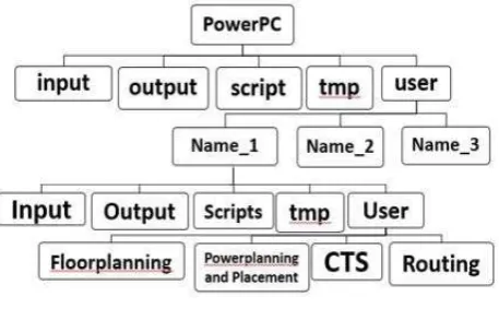
II. ARCHITECTURE
Architecture design methodology is an approach to PPC that implement in top-down
hierarchy for different Blocks of PPC. By introducing hierarchy into system, the design
system reduced in complexity as well as replicated many times. We made a different bucket
for design structure like input, output scripts, tmp, user and each of it for specific task. In
input bucket specified the design data Block along with library of technology (like .lib, .v,
.sdc, .tluplus, .map) which are pre-requisites for design. In output bucket, outcomes of design
in terms of final netlist, SPEF file for next step, GDS-II. In tmp bucket tools initialization file
is there it’s specifically required when we invoke the tools (like synopsys.dc.setup) [7]. Script
Bucket has various scripts for design step. While in user bucket is used for given access to
multiple user as per need. and also we can modify the buckets as per requirement.as we
moves to down in user (fig 2) different access is provide to user which can work on the
different stages. Where they can take the design and script for different block of processor
and start to implement design, which reduce TAT for PPC design.
III.TOOLS, TECHNOLOGY AND IMPLEMENTATION
This design is implemented on 90nm technology. The tool which is used for backend
synthesis is Design Compiler and for Physical implementation is IC Compiler. First Verilog
NOV-DEC, 2015, VOL-3/21 www.srjis.com Page 1410 Fig 2 Hierarchy of PPC
Command. This design is optimized according to constraints such as input delay [2], output
delay [2], and Clock frequency after setting technology library [1], link library [1].Different
techniques are used to optimize timing [3].
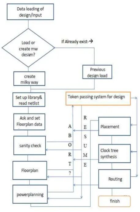
IV. DESIGN FLOW METHODOLOGY FOR PPC
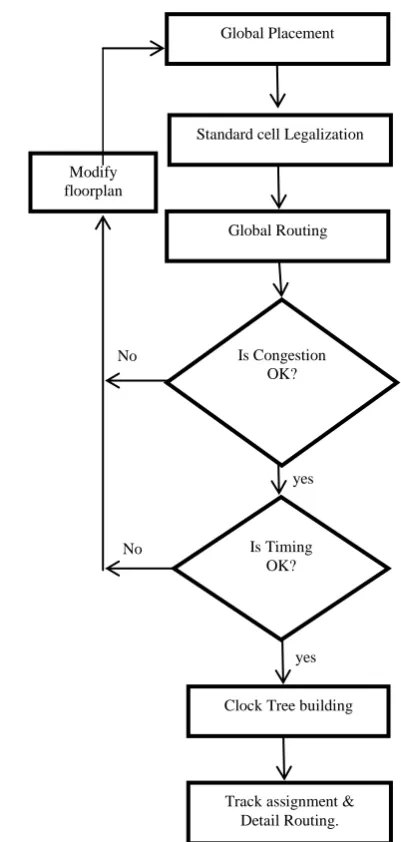
Here, Design flow chart(fig 3) illustrate physical design flow in way to do automatic task
which predefined in the script like generate report, create floorplan, placement, clock tree
synthesis, routing. And every checklist, input, output of the flow (stage of floorplan to
routing). Step start from design (block) loading of the PPC. Milky Way is design format to
save the design in ICC gives collection of files describing netlist, technology specifications
and parasitic information and map file used for floor planning [4]. And if design is already
implemented up to any stage of design, than it can be loadable.
Next step, set up library and read netlist has included files of .v, .tf, .lib, tluplus, .sdc, .map
[7]. A synthesized netlist (.v) after removal of timing violation describing connection as per
design. Technology file (.tf) having information about width, spacing, colour of metal layers,
via and dielectric and capacitance table. Technology library (.lib) specifies information about
macros and standard cell in terms of logic and timing. TLU PLUS file is lookup table which
contain the varying parasitic information related to change in operation conditions [4].
Constraint file (.sdc) is provided clock relation with signal. Mapping file is used to map
technology file and interconnect technology file.
Floorplan data will be set by user defined switch (while running script) is provided in
script.and set automatically in design. Sanity check option is addition option provided for
verify the design, library and timing of the loaded block. Floorplan stage with an aim to
reduce the chip area as well as minimize the delay, initialize the floorplan by selecting the
NOV-DEC, 2015, VOL-3/21 www.srjis.com Page 1411
structure on core area of the design [6]. Powerplanning script creates power rings, power rails
in the design automatically.
Token passing system for design stage gives flexibility in this flow for user to resume and
abort the design at any time without crash of current data and it will save the design at abort
stage and resume by this of the stage only.
Placement stage place standard cell in unit tile with optimization and legalization. Clock
Tree Synthesis stage has aim to provide clock source point to sinks. The goal of CTS is to
minimize skew and insertion delay [6]. Before CTS virtual clock, after CTS actual clock is
exist in design. Routing is the process of creating physical connection based on logic
connectivity. Signal pins are connected by routing metal interconnects.
Placement script will perform timing driven, congestion driven placement along with
legalize the standard cell which are overlapped. At that of time timing violation is removed
by replacing buffer in the design. Clock tree synthesis and routing script is also works on the
clock tree build up and routing of signal net in PPC [7]. So scripts are handy tool for EDA
[image:4.595.190.419.397.743.2]automation task which completely reduced the implementation time.
NOV-DEC, 2015, VOL-3/21 www.srjis.com Page 1412
V. FLOORPLAN AND POWERPLANN SCIRPT.
In the following, we present foorplan scripts with outcomes as well as for powerplanning. So,
floorplanning is process of arranging structure, placing close together in such way to meet the
timing and they occupy less area. And objective of floorplanning are to minimize are and
[image:5.595.194.413.179.339.2]delay [4].
[image:5.595.182.415.384.530.2]Fig 4 Floorplan script running
Fig 5 Floorplan output defining on console.
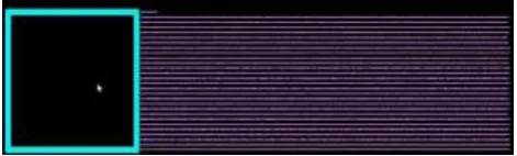
Fig 6 floorplanned structure of PPC-PLB
After reading netlist and setting up the library, script will ask for preparation data for
floorplan from user in terms of Utilization, aspect ratio, core to I/O boundary area (fig 4).
[image:5.595.180.416.581.652.2]NOV-DEC, 2015, VOL-3/21 www.srjis.com Page 1413
the result floorplan prepared just in two seconds(fig 5) and lastly procedure will trace token
and save it in one variable and GUI shows the floorplanned structure of PPC(fig 6).
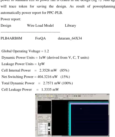
Powerplanning decide the power flow into PLB-PPC. Power rings is designed around the
core [4]. For that script will derive the PG connection and create the rectangular rings around
the core with higher metal layer along width of metal. Power ring drive power rails which fed
power to standard cell so power rail is crated in the design (fig 7). And again the procedure
will trace token for saving the design. As result of powerplanning stage generate
automatically power report for PPC-PLB.
Power report:
Design Wire Load Model Library
---
PLB4ARB8M ForQA dataram_64X34
Global Operating Voltage = 1.2
Dynamic Power Units = 1uW (derived from V, C, T units)
Leakage Power Units = 1pW
Cell Internal Power = 2.3528 mW (85%)
Net Switching Power = 404.3216 uW (15%)
Total Dynamic Power = 2.7571 mW (100%)
[image:6.595.70.440.183.626.2]Cell Leakage Power = 1.3335 mW
Fig 7 PLB-PPC with power Rings and Rail
VI. PLACEMENT, CTS AND ROUTING SCRIPT.
Placement, CTS, and routing scripts is integrate in one for designing. Goal of placement is to
place standard cell in way to match timing, and reduce congestion from design. Placement,
NOV-DEC, 2015, VOL-3/21 www.srjis.com Page 1414
stage of script , by executing the script, ICC tool[4] will throw the standard cell in core area
than it will legalize it means standard cell which are overlapped randomly will set on the
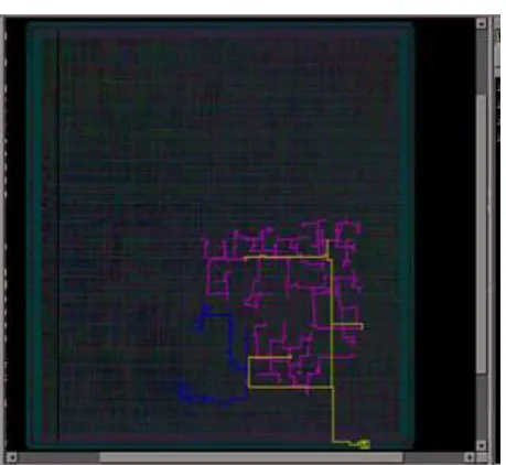
perfect area of the design(fig 9). Than global routing where no physical connection of signal
net exist. And report which is stored in the bucket of outcomes and again the design will
follow up the CTS stage where it will build up the clock tree by different technique H-tree
structure and mesh tree structure (fig 10) in CTS stage [4].
By following script, in routing stage the process of establishing physical connection between
the standard cell in design. Where tracks assigning to all metal layer through each GRC in
track assignment routing ,Next detail routing takes actual physical connection of metal and
via[11](fig 11). And lastly GDS-II, SPEF generated at this stage and netllist of the design will
be modified based on the stage [4].
[image:7.595.146.347.297.719.2].
Fig 8 Placement Flow
Global Placement
Standard cell Legalization
Global Routing
Is Timing OK? Is Congestion
OK?
Clock Tree building
Track assignment & Detail Routing. Modify
floorplan
yes
No No
NOV-DEC, 2015, VOL-3/21 www.srjis.com Page 1415 Fig 9 Placement of PLB-PPC
Fig 10 clock tree –multilevel building structure
[image:8.595.174.425.539.697.2]NOV-DEC, 2015, VOL-3/21 www.srjis.com Page 1416
VII. CONCLUSIONS
Hierarchy architecture explored for implementation of block level design of PPC flow.
Preliminary design requirement and block level design is stabilized by iteration based
execution of script in design which follows the Design flow of PPC.Token passing system
methodology for design is the new approach inside the flow for abort and resumes the design
any time. And script of design which automatically generate report and save it along with in
floorplan step user can define step in console itself.
We have described an effective and efficient interactive improvement method for
automation in physical design. It saves time to market and efforts. Automation can be more
effective with use of appropriate use of EDA tools. As technology is shrinking, Physical
design flow is becoming more complex so automation is also become very complex. Totally
automation is very difficult to make as Physical design flow is repeat process until desired
targets are not achieved.
FUTURE WORK
Rather than this flow worked for PPC design, but it also migrate to any macro based
design. To make one universal automated flow can work out for any design in Physical
design.
REFERENCES
Pinhong Chen, Desmond A, Kurt Keutzer, “Scripting for EDA Tools: A Case Study” IEEE-2001. Himanshu Bhatnagar, Conexant System Inc., ADAVANCE ASIC CHIP SYNTHESIS 2nd Ed: Ebook
ISBN 0-306-57507-3, KLUWER ACADEMIC PUBLISHERS.
J Bhasker, Rakesh Chadha, “Static timing analysis for Nanometer Designs: A practical Approach”, 2009ed ISBN-10:0387938192 Springer.
“Magic – A VLSI Layout system” http://www.research.digital.com./wrUprojects/magic .html Khosrow Golshan, “Physical Design Essentials: An ASIC Design Implementation Perspective”,
2007ed ISBN-10:0387366423 Springer.
K. J. Nowka, G. D. Carpenter, B.C. Brock, “The design and application of the PowerPC 405LP energy-efficient system on chip”, IBM J. RES& DEV. VOL. 47 NO. 5/6 SEP/NOV 2003. Generic 90nm library-synopsys for low Power design. [Online]. Available: http://www.
solvnet.synopsys.com
J.K Ousterhout, “Tcl and the Tk Toolkit” Addison-wesely, 1994.
Randal L. Schwartz, Tom Phoenix, Brian d foy, “Learning Perl”5th Ed, O’REILLY. Design Compiler® User Guide Version F-2011.09-SP2, December 2011.