© 2018, IRJET | Impact Factor value: 6.171 | ISO 9001:2008 Certified Journal | Page 458
INDIVIDUAL WHEEL CONTROL AND HAND BRAKE SYSTEM
Lt. Dr. M. Kalil Rahiman
1,
K. J. Kasi Venkatesh
2, M. Mohamed ashif
31Assistant professor(Si.G), Dept of Mechanical Engineering, Bannari Amman Institute of Technology,
Tamilnadu, India
2,3 Student, Dept of Mechanical Engineering, Bannari Amman Institute of Technology, Tamilnadu ,India
---***---
ABSTRACT: This project is about innovative idea used in automobiles vehicles. The hand brake controlled by lever jams sometimes. To overcome this lever jamming we have made an innovative idea to replace the brake lever to a switch type hand braking system and also to overcome the wheels drowned into the mud during rainy seasons.
This project consist a brake pedal, master cylinder, brake drum, control switch, brake union. In general, when the pedal is pressed ,brake oil in the master cylinder flows through the control switch and to the brake drum thus the rotor is stopped. In our project the pressure of the brake oil is controlled by control switch. The control switch controls the pressure of oil passing through it and a valve in the switch is closed hence the pressure remains maintained. Until the valve is opened the brake drum does not rotates.
I. INTRODUCTION
1.1Hydralic braking system
A hydraulic braking system transmits brake-pedal force to the wheel brakes through pressurized fluid, converting the fluid pressure into useful work of braking at the wheels. A simple, single-line hydraulic layout used to operate a drum and disc brake system is illustrated. The brake pedal relays the driver’s foot effort to the master-cylinder piston, which compresses the brake fluid. This fluid pressure is equally transmitted throughout the fluid to the front disc-caliper pistons and to the rear wheel-cylinder pistons. As per the regulations a separate mechanical parking brake must be incorporated with at least two wheels. This provision also allows the driver to stop the vehicle in the event of failure of the hydraulic brake system.
In a hydraulic braking system the braking force is directly proportional to the ratio of the master-cylinder cross-sectional area to the disc or drum-brake wheel-cylinder cross-sectional areas. Therefore these wheel-cylinder diameters are appropriately chosen to produce the desired braking effect. The wheel-cylinder cross-sectional areas of the front and rear disc-and drum-brakes respectively may be chosen to produce the best front-to-rear braking ratio. Hydraulic fluid is incompressible provided there is no trapped air in the system. If air is present in the braking circuit, the foot-brake movement becomes spongy.
The friction is caused by the fluid pressure squeezing the seal lips against the cylinder walls as the piston moves along its stroke. A hydraulic braking system is suitable only for intermittent braking applications, and a separate mechanical linkage must be incorporated for parking brakes.
Hydraulic brakes provides leverage ratios far higher than mechanical brake systems, they are compact and
easy to maintain and service and do not suffer from
wear in linkages that have obsoleted their predecessors which were linked or mechanical or even cable brakes.
The brake fluids used in hydraulic brakes must be changed and flushed periodically as most hydraulic brakes use glycol fluids which are hygroscopic which means they absorb moisture.
1.2Master cylinder
In automotive engineering, the master cylinder is a control device that converts non-hydraulic pressure (commonly from a driver's foot) into hydraulic pressure. This device controls secondary cylinders located at the other end of the hydraulic system.
As piston(s) move along the bore of the master cylinder, this movement is transferred through the hydraulic fluid, to result in a movement of the secondary cylinder(s). The hydraulic pressure created by moving a piston (inside the bore of the master cylinder) toward the secondary cylinder(s) compresses the fluid evenly, but by varying the comparative surface-area of the master cylinder and/or each secondary cylinder, one can vary the amount of force and displacement applied to each secondary cylinder, relative to the amount of force and displacement applied to the master cylinder.
© 2018, IRJET | Impact Factor value: 6.171 | ISO 9001:2008 Certified Journal | Page 459 (much like hydraulic clutches typically have only 1
piston per master cylinder). Each piston in a master cylinder operates a brake circuit, and for modern light trucks and passenger cars, usually a brake circuit leads to a brake caliper or shoe on only two of the vehicle's wheels, and the other brake circuit provides brake-pressure to slow down and stop the other two wheels. This is done in a diagonally split hydraulic system.
This lets the primary piston build up only a small amount of pressure until the secondary piston bottoms in the cylinder bore. Then the primary piston will build enough hydraulic pressure to operate the brakes served by this half of the system. In case of a hydraulic failure in the brake system served by the primary piston, the primary piston will move forward when the brakes are applied but will not build up hydraulic pressure. In this case very little force is transferred to the secondary piston through the primary piston spring until the piston extension screw comes in contact with the secondary piston. Then, pushrod force is transmitted directly to the secondary piston and enough pressure is built up to operate its brakes. Usually the 2 systems are split into left front and right rear comprising one system and right front and left rear comprising the other system. For safety, this is done so that usually only two wheels lose their braking ability at the same time and that both sides of the car have at least one braking system working and both ends of the car have at least one system working. With only 1 system working there is longer stopping distances and repairs should be done before driving again.[1]
1.3 Schematic diagram of master cylinder
Fig 1. Schematic diagram of master cylinder
1.4Diagonal braking
The diagonal split concept comes from the fact that the left rear and right front brakes are on one hydraulic line while the right front and left rear brakes are on another. The diagonal split system, because it maintains braking ability for both a front and rear tire, is easier for the driver to control the vehicle in emergency brake failure.
[image:2.595.330.543.478.628.2]In a non-diagonal system, all the braking power would transfer to either just the front or back tires, increasing the likelihood of skidding and possibly losing control.
Fig 2.Diagonal brake circuit
Sometimes, split braking systems use two master cylinders to control each conduit (brake line). This is akin to a double safety back-up. Since master cylinders exponentially increase the force of the hydraulic fluid to the brakes, should one fail, the vehicle still has stopping capability, albeit the stopping distance is greater and less even (more difficult to control). On the other hand, with two master cylinders, the system has one more additional part that could fail, but engineers consider that the safety features outweigh the potential for failure if properly maintained.
1.5Schematic diagram of hydraulic braking system
Fig 3. Schematic diagram of hydraulic braking system
2.HAND BRAKES IN AUTOMOBILES
[image:2.595.81.274.479.625.2]© 2018, IRJET | Impact Factor value: 6.171 | ISO 9001:2008 Certified Journal | Page 460 directly connected to the brake mechanism on one end
and to a lever or foot pedal at the driver's position. The mechanism is often a hand-operated lever (hence the
hand brake name), on the floor on either side of the driver, or a pull handle located below and near the steering wheel column, or a (foot-operated) pedal located far apart from the other pedals.
Although sometimes known as an emergency brake, using it in any emergency where the footbrake is still operational is likely to badly upset the brake balance of the car and vastly increase the likelihood of loss of control of the vehicle, for example by initiating a rear-wheel skid. Additionally, the stopping force provided by using the handbrake is small and would not significantly aid in stopping the vehicle. The parking brake operates generally only on the rear wheels,[2] which have reduced traction while
braking but in some cases, parking brake operates on the front wheels, as done in most Citroens manufactured since the end of World War II. The hand brake is instead intended for use in case of mechanical failure where the regular footbrake is inoperable or compromised. Modern brake systems are typically very reliable and equipped with dual-circuit hydraulics and low-brake-fluid sensor systems, meaning the handbrake is rarely used to stop a moving vehicle.
The most common use for a parking brake is to keep the vehicle motionless when it is parked. Parking brakes have a ratchet locking mechanism that will keep them engaged until a release button is pressed. On vehicles with automatic transmissions, this is usually used in concert with a parking pawl in the transmission.
Handbrakes are never used to slow the vehicle when it is in motion, as doing so generally locks only the back wheels and sends the car into a handbrake turn. Handbrake turns are often used in street racing to initiate drifting, but such a maneuver is often seen as an error among regular road users, and is dangerous in many situations.
2.1 Hand brake lever
Fig 4.Hand brake lever
2.2Failures in Hand brakes
Common reasons for this to happen:
Worn or broken parking brake cable: Not using your parking brake is a common reason for failure. Even though the parking brake cable is housed in a protective sleeve, with infrequent use, the cable can become corroded and rusted. This can result in cable failure just when you need it the most. Everyday use prevents buildup and keeps the cable in good condition.
Seized parking brake: Another cause for parking brake failure is driving with the parking brake engaged. This will overheat your parking brake, prematurely wearing the brake pads or shoes, and possibly lock up your wheels. It is important to remember to release your parking brake before shifting your vehicle into “drive” or “reverse.”
Broken parking brake lever: The parking brake is a self-locking system. When activated, it is designed to lock in place until you press a button or pull a lever to release it. Over time, the springs inside the parking brake lever can fatigue and break.
Faulty parking brake sensor: One of several sensors that activates the red brake warning light on your dashboard, the parking brake sensor informs you when the parking brake is still engaged. Newer cars also use this sensor to alert the driver with an audible “ding.” When this sensor fails, your brake warning light on your dashboard stays illuminated, even if the parking brake has been released.
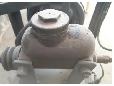
3. SWITCH
Fig 5.Switch
3.1Working of switch type hand braking system
The switch type hand braking system is used to
© 2018, IRJET | Impact Factor value: 6.171 | ISO 9001:2008 Certified Journal | Page 461
The pressure applied on the brake pedal is
transferred to master cylinder.
The fluid passes through the brake lines equally
in all directions due to Pascal's law.
The fluid passes through the pressure control
valve and presses the brake pads to stop the rotor.
By pressing the brake pedal, the switch is closed.
Thus the brake fluid over inlet of the switch is
free and returns back to the master cylinder.
But the fluid over the other side gets arrested by
the switch.
Hence the brake will be applied over disc until
the switch is realized.
4. COMPARISION OVER NORMAL HAND BRAKE
Normal hand brake lever fails due to loss of
friction between brake pad and propeller shaft.
The switch type hand braking system arrests the
pressure and makes it effective braking than normal hand brakes.
Normal hand braking system are applied on rear
wheels, whereas switch type hand braking system can be applied on both front and rear wheels.
There is a separate circuit or connection for
parking brake system, whereas the switch type hand braking system are installed between the
brake lines reducing the weight.
5. ADVANTAGES OVER NORMAL HAND BRAKES
Until the pressure control valve is released the
rotor doesn’t moves which makes the car to be in ideal position.
It is more effective than parking brake system.
It is compact.
Cost efficient
Replacement is easy
6. INDIVIDUAL WHEEL CONTROL
In this system each wheels are controlled individually using the same switch used in the braking system. Here each switches are connected to each wheel brake lines. If any one of the wheel gets drowned into mud, in case left wheel gets drowned into mud, the left wheel switch in closed on pressing the brake pedal. Thus the brake is applied only on the left wheel. Hence the engine power is fully transmitted to the right side wheel with the help of
differential. Hence the left is pulled by the other wheels from the drowned surface.
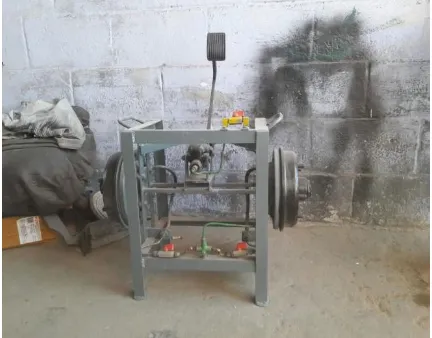
6. A) OUR PROJECT PHOTO
6.1 DIFFERENTIAL UNIT
A differential is a gear train with three shafts that has the property that the angular velocity of one shaft is the average of the angular velocities of the others, or a fixed multiple of that average.
[image:4.595.329.545.117.286.2]
In automobiles and other wheeled vehicles, the differential allows the outer drive wheel to rotate faster than the inner drive wheel during a turn. This is necessary when the vehicle turns, making the wheel that is traveling around the outside of the turning curve roll farther and faster than the other. The average of the rotational speed of the two driving wheels equals the input rotational speed of the drive shaft. An increase in the speed of one wheel is balanced by a decrease in the speed of the other.
Fig 7.Differential Unit
© 2018, IRJET | Impact Factor value: 6.171 | ISO 9001:2008 Certified Journal | Page 462 gearbox shafts transverse, and with the pinion on the
end of the main-shaft of the gearbox and the differential enclosed in the same housing as the gearbox. There are individual drive-shafts to each wheel. A differential consists of one input, the drive shaft, and two outputs which are the two drive wheels, however the rotation of the drive wheels are coupled to each other by their connection to the roadway. Under normal conditions, with small tire slip, the ratio of the speeds of the two driving wheels is defined by the ratio of the radii of the paths around which the two wheels are rolling, which in turn is determined by the track-width of the vehicle (the distance between the driving wheels) and the radius of the turn.
6. CONCLUSION
Hence by using this INDIVIDUAL WHEEL CONTROL AND HAND BRAKE SYSTEM , the failure, accidents can be reduced and also the recovery of wheels from mud becomes easy. It occupies less space and also the space for hand brake lever can be eliminated.
7. REFERENCES
1.Dr.Kirpal Singh, Automobile Engineering. Vol.2, Standard Publishers Distributors, 2009.
2. Sean Bennett (3 November 2006). Modern Diesel
Technology: Brakes, Suspension & Steering.