© 2017, IRJET | Impact Factor value: 6.171 | ISO 9001:2008 Certified Journal | Page 978
PIPE CONVEYOR
Sumit Batwe
1, Santosh Jaju
2, Suryakant Vaidya
31
Student,
2Assistant Professor,
3Manager
1,2
Department of Mechanical Engineering,
1,2GHRCE, Nagpur, India
3
MANIKGARH CEMENT,GADCHANDUR, CHANDRAPUR
---***---Abstract:
Pipe conveyors are becoming more popular inthe bulk material handling sector. They are applied when the installation of a belt conveyor is required in difficult topographical conditions, rough weather conditions, and for the transportation of dusty, contaminated, and toxic materials. New innovations in the pipe conveyor and belt are advanced to elaborate the growth in its capacity, length and complexity of pipe conveyor . Enhanced belt construction can offer better stability during horizontal curves and resistance to twist. LRR pipe conveyors with arubber compound can significantly lower the power consumption and belt tension, producing capital and operation cost savings. Dynamic analysis systems , are used to analyse the conveyor’s starting and stopping behaviourwhich in further can improve the design and reliability of long pipe conveyor systems. For these three aspects, technical backgrounds and field installations as examples are discussed.
Key Words: Pipe Conveyors, Three Point Testing, Six point Testing, Modelling, Dynamic Analysis,
PROBLEM DISSCUSSED
Manikgarh cement has 7.8 km line from the mines to the unloading station . For the Unit I there is ropeway bucket system with each capacity of 2 MT and the total no. of buckets are 300 having and total capacity of 600 TPH. Inspite of this it requires more maintaince cost and power, energy consumption and may cause accidents and failures due to misalignment of bucket.Similarly, a new system has been setup for unit II which comprises pipe conveyor which has a total capacity of 750 TPH and is more efficient as compared to ropeway system.
INTRODUCTION
Belt conveyors mainly for transporting materials, and are widely implemented in the mining, power generation, cement, ship port and industrial plants for several decades. The main benefit of belt conveyors compared to other material handling machines like trucks, trains and barges
is the higher efficiency in the mechanical system, energy consumption and total cost over the long term, especially when conveyor system is design optimized . Trough belt conveyor is the ubiquitous type of belt conveyor. There are other belt conveys serving more specialized purposes, like pipe conveyors or tubular conveyors, high incline or high angle conveyors, wheel-on-rope type of conveyors like cable conveyors and Ropecon. Pipe conveyor was first installed in 1980s in Japan , the actual advantages of using pipe conveyor was its capabiitt to accomplish sharp curves and seal the transporting material. Rolling the belt into the pipe shape separates the material from the environment. It also minimizes the area and moment of inertia, which facilitates the bending of the pipe belt over horizontal and vertical curves. Over the last fifteen years, pipe conveyor saw not only increased number of installations and growth in the size and complexity of the system, but also better recognition by the general material handling sector as a feasible material handling system. India and China now represent the biggest market for pipe conveyors. In south east Asia , Australia and South America, a few major pipe conveyor installations are either operating, being erected or under planning. If these initial high profile systems get to be successful, it is reasonable to expect that more pipe conveyors will be planned and installed during the next decade in these areas. In further decades south east Asia, Australia and south America important new markets for pipe conveyors.
© 2017, IRJET | Impact Factor value: 6.171 | ISO 9001:2008 Certified Journal | Page 979 How to ensure a reliable, economic and optimized design
of pipe conveyor systems is important to the system engineer, components supplier, the user/client, and the pipe conveyor sector itself. Main advantage of using a pipe conveyor, instead of a conventional open belt conveyor, are the ability to transport material completely enclosed with a better system design, and its geometrical flexibility. Increase in demand for pipe conveyor installations justifies research into the power consumption of pipe conveyors that significantly depend on rolling resistance forces.In this article, We have attempt to illustrate some analysis and recent progress that bears importance to the pipe conveyors.
PIPE BELT DESIGN TESTING AND MODELLING
Pipe conveyor system has a much greater significance over other conveyor in terms of system performance . The main factor is the pipe belt stiffness. As the belt is rolled into pipe shape from flat shape, the bending stiffness of the belt gets turns into the contact pressure on the surrounding idler rollers. Higher belt stiffness will have a resultin higher contact pressure. This gives the pipe belt more stability and also a better resistance to twist and to collapse during horizontal and vertical curves. During this it may result in increased power consumption, increased belt tension and all related results like as necessity for strength belt and larger drive size. From the design point of view, there is a balance in the belt stiffness to gain for each individual project. If the conveyor routing is straightly perfected , there is no need to design a pipe belt with high belt stiffness. Lower power consumption and capital cost can be achieved. If the conveyor routing has a lot of horizontal and vertical curves with small curve radius, the belt stiffness should be increased as accordingly to manage the bending effect for curves, so that the belt does not have additional rotations, twist and collapse. It must include both the belt manufacturer and system engineer's responsibility to work together and to determine the suitable belt stiffness for each installation.
There are many different ways in designing the belt stiffness. They generally fall into two major categories: experimental method and numerical method. .
Early analysis of pipe conveyors are based on analytical simplification of the pipe belt behaviour. Now in recent , the finite element analysis (FEA) is gaining more popular to simulate the pipe folding and curving behaviour. . However, the FEA of pipe conveyor belts is a highly nonlinear simulation and more expensive. Using coarse
mesh with few elements, unrealistic boundary conditions and inaccuracyof material properties calibration will make the simulation results less than useful.
Conveyor Dynamics Inc. and Veyance Technologies Inc. both together developed the Goodyear Confine steel cord and fabric pipe conveyor belts. Confine pipe belt has a unique design, as shown in Fig1 and Fig4 for the steel cord version. There are mainly three different zones in the belt: a center tension carrying zone along with steel cords, secondly an overlap zone with reduced number of steel cords, and a junction zone having no steel cords.
[image:2.612.347.549.360.544.2]The center tension carrying zone lowers the center of gravity of the belt, because there are more steel cords at the centre. It makes pipe belt more stable and resistant to rotation. The junction zone reduces the belt deformation and occurence of collapse during curves, because no bending forces from tensioned steels are existing in the junction zone. The overlap zone provides a tight sealing on the pipe belt.
Figure 1. 1600mm wide ST1250 Confine Pipe Belt.
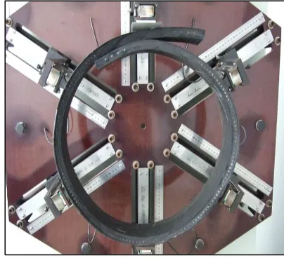
© 2017, IRJET | Impact Factor value: 6.171 | ISO 9001:2008 Certified Journal | Page 980 Figure 2. 3 point bending stiffness test.
Figure 2 shows a three point bending stiffness testing device. The three point bending is a well defined and caliberated bending test. As Compared to the six point stiffness test, it is much easier to make test samples and generate design libraries based on the three point bending test. It requires a good numerical and experimental correlations between the three point bending stiffness and the six point pipe belt stiffness . Once they are established there is no need to verify full width belt samples and go through a trial-and-error process for each designed belt before the actual belt production.
Figure 3. Pipe belt transition test
Confine belt construction can withstand several transitions between the flat belt and the folded belt.
Finite element analysis (FEA) is also used extensively to equip the design of the confine pipe belt. Other FEA of pipe belts, simplified shell or sold elements are used to represent both rubber, steel cord and fabric materials, a complete model where the rubber, steel cords and fabric layers are modeled individually with their own material properties .The overall bending form of pipe belt in FEA is calculated with both the three point bending and six point stiffness testing . Figure 4 shows such a FEA model of a 500mm diameter ST4000 pipe belt .With FEA, various operating factors can be exanined. Pipe belt carrying material can be modeled, to examine the various effects of belt sag and belt deformation from material loading.
Figure 4. FEA of 500mm ST4000 Confine Pipe belt.
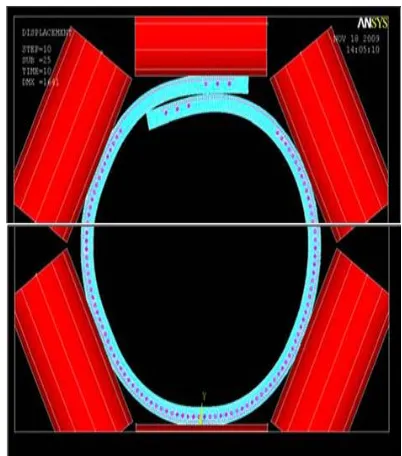
[image:3.612.348.549.296.524.2] [image:3.612.61.264.472.683.2]© 2017, IRJET | Impact Factor value: 6.171 | ISO 9001:2008 Certified Journal | Page 981 Figure 5. FEA simulation of Confine (left) and
conventional (right) pipe belt during horizontal curves.
Figure 5 shows a conventional steel cord pipe belt deforms at horizontal curves due to the bending effect of the tensioned belt (right image). The pipe belt lose contact with the idler rollers and its diameter decreases. If the belt stiffness increases, such deformation will decrease. The pipe belt fabrication also affect the belt behavior during curves, where the Confine belt is checked to provide better resistance to deformation, twist and rotation even with the same belt stiffness (left image). Modelingof pipe conveyor belt behavior during the curves is quite complex, in addition to the other complexities of modeling and calibrating individual materials like rubber, fabric and steel cords. Such demanding simulations become feasible only in recent years due to the fastly growth in computing power with decreasing cost.
APPLICATION OF FINE CONFINE BELT
Ever since the newly launch of the Goodyear Pipe Belt Project in 2008, over 40km long of Confine steel cord and fabric pipe belts have been installed and running successfully with a possituve results . Besides regular belts, special types of pipe belts are also manufactured to meet the customer need.
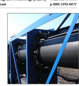
Figure 6. 400mm diameter ST1100 Low Rolling Resistance Pipe Belt.
Figure 6 shows a 400mm diameter pipe belt with Low Rolling Resistance pulley cover compound which is installed in a power plant at Bulgaria. The conveyor is long as about 2.7km. The main neccesity of LRR pipe belt is to reduce the power consumption and belt tension. This is also the world's first LRR pipe conveyor belt. For long pipe conveyors, every 10% reduction in power consumption will have significant impact on the whole system capital cost and operating cost, as well demonstrated in overlong trough conveyors.
[image:4.612.55.269.70.331.2]© 2017, IRJET | Impact Factor value: 6.171 | ISO 9001:2008 Certified Journal | Page 982 Figure 8. 350mm diameter ST2000 EPDM heat resistant
pipe belt, with material temperature 180°C.
Figure 8 shows a 2-flight, 4km centerto center length 350mm diameter heat resistant EPDM (Solarshield®) pipe belt. The maximum material temperature it can withstand is 180°C. The first 3.4km long flight has a ST2000 steel cord belt while the second flight has a ST630 steel cord belt. Figure 9 shows two parallel 300mm diameter heat resistant EPDM fabric pipe belts with breaking strength of 800N/m. The material temperature withstand capablity is 180°C. The third conveyor has a regular temperature 400mm diameter fabric pipe belt having 800N/mm breaking strength
DYANAMIC
ANALYSIS
AND
SYSTEM
OPTIMIZATION
Conveyor Dynamics, Inc. developed a more fundamental way to calculate the belt tension and power consumption for pipe conveyors. Firstly, the pipe belt stiffness is determined bm on the basis of maximum belt tension and smallest curve radius, so as to prevent excessive belt rotation and twist , and prevent high power requirement from excessive belt stiffness. The optimized belt stiffness, contact pressure on the idler rollwr can be obtained by FEA and experimental data. This contact pressure changes with belt tension, material loading and conveyor shape. The viscoelastic properties of the rubber compound are measured on the Dynamic Mechanical Analysis (DMA)
machine. From the viscoelastic properties and contact pressure, the indentation losses over each idler can be calculated. This method approach the problem of calculating pipe conveyors from fundamental physics, rather on the basis of empirical relations. It consists design optimization based on LRR and design for specialty belts such as heat resistant pipe belts, as the range of design problems that can be illustrated is much wider. Conveyor Dynamics, Inc. is been a world leader in dynamic analysis of conveyor design since mid 1980s. Dynamic analysis is a powerful tool to examine the conveyor starting and stopping behavior.
[image:5.612.349.550.251.450.2]© 2017, IRJET | Impact Factor value: 6.171 | ISO 9001:2008 Certified Journal | Page 983 more complicated routing, and the dynamic analysis
becomes more important.
CONCLUSION
Some of the intrestive topics on pipe conveyor belt and system are discussed in this paper, in relationwith the patented Goodyear Confine Pipe conveyor belt. Both Experimental testing and numerical simulation on pipe conveyor belt are being reviewedin this paper . Field installations with specialty belt such as low rolling resistance belt and heat resistant belt are also demonstrated as successful implementation of the Confine pipe belt. Low rolling resistance belt, with betterconsideration of the mechanics of the pipe belt and pipe conveyor system, and system control from dynamic analysis will give a better performance. long pipe conveyor systems can become more competitive and reliable.
REFERENCES
1. Nordell, L. (1996), "The Power of Rubber - Part I", Bulk Solids Handling, 16(3).
2. Staples, P. (2002), "The History of Pipe Conveyors", Bulk Solids Handling, 22(3).
3. Hotte, S., L. Overmeyer, and T. Wennekamp (2011), "Research on the Form Force Behavior of Pipe Conveyors in Different Curve Radii", in Bulk Solids India 2011, India.
4. Schilling, O., M. Westerwald, and J. Wiedenroth (2007), "ABAQUS FE Analysis of a Pipe Conveyor Using Solids with Embedded Truss Elements and Shells with Rebar Layers", in NAFEMS Seminar: Simulating Composite Materials and Structures.
5. Imai, A. (2011), "Pipe Conveyor Development, Benchmark and Future Trend", in Bulk Solids India 2011, India.