© 2017, IRJET | Impact Factor value: 5.181 | ISO 9001:2008 Certified Journal
| Page 1354
STRESS ANALYSIS ON SPLIT RING
Y. B. Deshmukh
1, Dr. D. V. Bhope
21
M-Tech (CAD/CAM) Student IV semester,
Rajiv Gandhi College of Engineering Research & Technology, Chandrapur-442401
2
Professor “Mechanical Engineering Department”
Rajiv Gandhi College of Engineering Research & Technology, Chandrapur-442401
---***---Abstract -
In the present work, the finite element approachis used to evaluate the stresses in the rotating split ring and split ring subjected to bending moment with central circular by varying the diameter and size of hole present at various pitch circle diameter on split ring. An effort is made to study the effect of 4 numbers of holes and 8 numbers of holes on stress concentration factor in the split ring. This analysis reveals that the stress distribution & its magnitude in the split ring are affected due to split angle, size and number of discontinuities.
Key Words: Split Ring, Rotating, Bending.
NOTATION
Ri inner diameter (mm)
Ro outer diameter (mm)
D1 Outer diameter of ring (mm)
D2 Inner diameter of ring (mm)
E Modulus of Elasticity (N/mm2)
ʋ Poisson ratio
ρ Density of material (Kg/mm3 ) ⍵ Angular velocity of ring (red/sec) N Rotation of ring
ϴ Angles (Degree)
σϴ Hoop stress & tangential stress (MPa)
σr Radial stress (MPa)
d Diameter of hole (mm) Dp Pitch circle diameter (mm) d Diameter of hole (mm) SCF stress concentration factor
1. INTRODUCTION
Split ring or retaining ring is used for locating machine part. These elements are snapped into a circumferential groove machined in a shaft or a housing to form an artificial shoulder.
They are installed into a groove creating a shoulder that retains the assembly. Retaining rings are more efficient and cost-effective than traditional fasteners like screws, nuts, bolts, cotter pins, washers and more, and they do it with a minimum amount of surface preparation to either shaft or housing (12). They are subjected to centrifugal loads in case of rotation and also the bending loads.
The finite element approach is used to evaluate the stresses in the rotating split ring with central hole by varying the diameter of hole present at various pitch circle diameters Dp on split ring.
Later, the finite element approach is used to evaluate the stresses in the split ring with central hole subjected to bending moment with central hole by varying the diameter of hole present at various pitch circle diameters Dp on split
ring. The bending load is applied by considering the pressure of P = 100 N/mm2 acting normal to the split faces.
The various geometric parameter ratios considered for present analysis are as follows,
D1 = 200 mm, D2=100 mm
ϴ = 10˚, 45˚, 90˚, 135˚& 180˚ d = 10, 20, 30, and 40 mm
Dp/D = 0.5, 0.6, 0.7, 0.8, 0.9, and 1.0
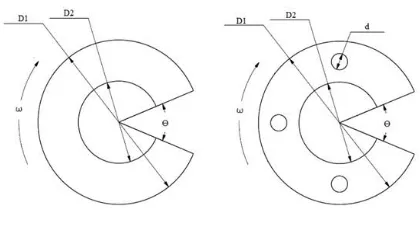
The geometry of split ring without hole and with holes is shown in fig. 1.1 & 1.2 respectively.
[image:1.595.332.542.501.616.2]
Fig. 1.1 Solid Split Ring Fig. 1.2 Split Ring with Hole
The ring has a modulus of elasticity (E) 200X103 MPa
(N/mm2) and Poisson’s ratio (ʋ) 0.3 which is rotating at
1000rpm, and material density (ρ) of 7.8x10⁻⁶ kg/mm3.
© 2017, IRJET | Impact Factor value: 5.181 | ISO 9001:2008 Certified Journal
| Page 1355
2. ANALYTICAL & FE ANALYSIS OF FULL RING
There are mainly two types of stresses induced in the rotating ring i.e., radial stress and hoop stress as given by following equations.
The equation for a solid ring is as follows,
Radial stress, with Maximum value of
stress is at ,
Hoop stress, with Maximum
value of stress is at inner radius Ri
The hoop stress and radial stress can be evaluated using analytical equation as follows,
Hoop stress can be calculated as follows, Hoop stress, Max at r = a
Hoop stress,
=742.393 MPa (N/mm2)
Radial stress can be calculated as follows, Radial stress, Max at r =
Radial stress,
=
= 88.125 MPa (N/mm2)
FE approach is also used to determine stress in the full ring and the comparison between the FE Result and analytical results is given in Table 2.1.
Table 2.1 Comparison of FE and Analytical Results
Stresses FE (MPa)
Analytical (MPa)
σϴ 92.152 88.125
σr 747.537 742.393
It is observed from Table 2.1 that the analytical stresses and FE stresses are in close agreement. This justifies the validity of FE approach.
3. STRESS ANALYSIS OF ROTATING SOLID SPLIT
RING
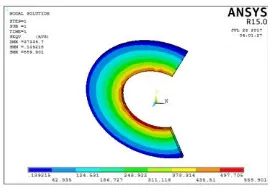
The finite element approach is used to evaluate the stresses in the rotating split ring with central hole by varying the split angles as 10˚, 45˚, 90˚, 135˚, and 180˚. The body force is applied corresponding to angular velocity ⍵ =104.67rad/sec
about Z-axis. The figure 3.1 and 3.2 shows the Von-mises stress contour for various split angles. The FE results are given in Table 3.1.
[image:2.595.368.502.227.324.2]Fig. 3.1: Von-mises contour for split angle of 10˚
[image:2.595.346.547.378.576.2]
Fig. 3.2: Von-mises Stress Contour for split angle 135˚
Table 3.1: stress comparison of rotating full split ring
Split angle “ϴ” 1st Principle stress N/mm2 2nd Principle stress N/mm2 Von-mises stress N/mm2 Stress w. r. t. split ring SCF=б/бf
FULL 380.68 139.972 337.494 - 10: 516.394 24.35 519.838 1.039676 45: 506.811 24.438 519.135 1.03827 90: 681.169 57.112 629.481 1.258962 135: 566.189 85.385 559.901 1.119802 180: 532.665 24.119 535.997 1.071994
Fig. 3.1: Variation of Stresses with Respect to Split Angle
In fig.3.1, 1st principle and Von-mises stresses in split ring
increases till the split angle of 90˚ and it remains almost constant after split angle of 90˚. It is also observed that radial stresses are lesser in magnitude as compared to hoop stresses
.
4. STRESS ANALYSIS OF ROTATING SPILT RING
WITH HOLES
© 2017, IRJET | Impact Factor value: 5.181 | ISO 9001:2008 Certified Journal
| Page 1356
effect of 4-number of holes and 8-number of holes on stress concentration factor in the split ring.
The stresses are determined in rotating split ring by varying the split angle as 10˚, 45˚, 90˚, 135˚, & 180˚. In this study, the following cases are considered to evaluate the stresses in rotating split ring with 4-holes and 8-holes which are situated at pitch circle diameter Dp corresponding to the
various ratio of Dp/D.
Case 1 Split ring with holes, for Dp/D = 0.75
Case 2 split ring with holes, for Dp/D = 0.5
Case 3 Split ring with holes, for Dp/D = 0.6
Case 4 Split ring with holes, for Dp/D = 0.7
Case 5 Split ring with holes, for Dp/D = 0.8
Case 6 Split ring with holes, for Dp/D = 0.9
Case 7 Split ring with holes, for Dp/D = 1.0
[image:3.595.327.552.63.303.2]Variation of SCF for Dp/D=0.75 are shown in fig. 4.1 and 4.2
[image:3.595.57.269.329.538.2]Fig.4.1: Variation of SCF for Dp/D = 0.75 (4-holes)
Fig.4.2: Variation of SCF for Dp/D = 0.75 (8-holes)
Fig. 4.1 indicates that the stress concentration factor (SCF) in rotating split ring remain almost constant up to 90: then it suddenly increases till split angle of 135˚ and decreases till 180˚. It observed that the maximum SCF is for the split angle of 135:.
In fig. 4.2, it is observed that the hole diameter of 40 mm leads to maximum stress concentration factor in the split ring. It is seen that the hole diameter of 10 mm leads to increase in the SCF with respect to split angle variation.
Variation of SCF for Dp/D=0.5 are shown in fig. 4.3 and 4.4
[image:3.595.63.268.444.539.2]Fig.4.3: Variation of SCF for Dp/D = 0.5 (4-holes)
Fig. 4.4: Variation of SCF for Dp/D = 0.5 (8-holes)
Fig. 4.3 indicates that the SCF in rotating split ring remain almost constant up to 90: then it suddenly increases till split angle of 135˚ and decreases till 180˚ split angle. It observed that the maximum SCF is for the split angle of 135:.
In fig. 4.4, it is observed that the hole diameter of 30 mm leads to maximum SCF in the split ring. It is seen that the hole diameter of 10 mm SCF leads to increase in the SCF with respect to split angle variation.
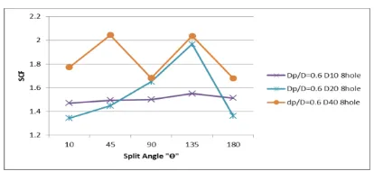
Variation of SCF for Dp/D=0.6 are shown in fig. 4.5 and 4.6
Fig. 4.5: Variation of SCF for Dp/D = 0.6 (4-holes)
Fig. 4.6: Variation of SCF for Dp/D = 0.6 (8-holes)
[image:3.595.326.541.467.588.2] [image:3.595.330.537.608.703.2]© 2017, IRJET | Impact Factor value: 5.181 | ISO 9001:2008 Certified Journal
| Page 1357
SCF is for the split angle of 135:. It is seen that the hole diameter of 10 mm SCF leads to increase in the SCF with respect to split angle variation.
In Fig. 4.6, it is observed that the hole diameter of 40 mm induces maximum SCF. It observed that the maximum SCF is for the split angle of 45˚ and 135:. It is seen that the hole diameter of 10 mm SCF leads to constant increase in the SCF with respect to split angle variation.
Variation of SCF for Dp/D=0.7 are shown in fig. 4.7 and 4.8
Fig. 4.7: Variation of SCF for Dp/D = 0.7 (4-holes)
Fig. 4.8: Variation of SCF for Dp/D = 0.7 (8-holes)
Fig. 4.7 indicates that the SCF in rotating split ring remain almost constant up to 135˚ and decreases till 180˚. It observed that the maximum SCF is for the split angle of 135:.
In fig. 4.8, it is observed that hole diameter of 20 mm and 30 mm are having approximately same magnitude of SCF. It is seen that the hole diameter of 10 mm, leads to increase in the SCF with respect to split angle variation.
Variation of SCF for Dp/D=0.8 are shown in fig. 4.9 and 4.10
Fig. 4.9: Variation of SCF for Dp/D = 0.8 (4-holes)
Fig. 4.10: Variation of SCF for Dp/D = 0.8 (8-holes)
Fig. 4.9 indicates that the SCF in rotating split ring remain almost constant up to 135˚ and decreases till 180˚. It is observed that the maximum value of SCF is for the split angle of 180˚.
In fig. 4.10, it is observed that, the diameter of hole of 10 mm is having maximum values of SCF as compare to other hole diameters.
Variation of SCF for Dp/D=0.9 are shown in fig. 4.11 and 4.12
Fig. 4.11: Variation of SCF for Dp/D = 0.9 (4-holes)
Fig. 4.12: Variation of SCF for Dp/D = 0.9 (8-holes)
Fig. 4.11 indicates that the SCF in rotating split ring remain almost constant up to 90˚ and decreases till 180˚ but it differ for diameter of hole 10mm. It observed that the maximum value of SCF is for the split angle of 90:.
Fig. 4.12 it is seen that the hole diameter of SCF leads to constant increase up to 180˚. It is observed that the maximum value of SCF is for the split angle 45˚ & 135˚.
© 2017, IRJET | Impact Factor value: 5.181 | ISO 9001:2008 Certified Journal
| Page 1358
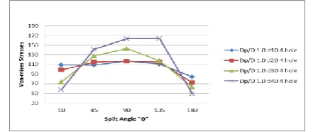
Fig. 4.13: Variation of SCF for Dp/D = 1.0 (4-holes) [image:5.595.55.268.223.322.2]Fig. 4.14: Variation of SCF for Dp/D = 1.0 (8-holes)
Fig. 4.13 indicates that the SCF in rotating split ring remain almost constant up to 135: then it suddenly increases till split angle of 180˚. It observed that the maximum SCF value is for the split angle of 90:.
Fig. 4.14 indicates that the SCF in rotating split ring remain almost constant variation up to 135: then it suddenly increases till split angle of 135˚. It observed that the maximum value of SCF is for the split angle of 180:.
5. STRESS ANALYSIS OF SOLID SPLIT RING
SUBJECTED TO BENDING LOAD
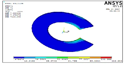
The finite element approach is used to evaluate the stresses in the rotating split ring with central hole by varying the split angles as 10˚, 45˚, 90˚, 135˚and 180˚. The bending load is applied by considering the pressure of P = 100 N/mm2 acting
[image:5.595.335.535.268.371.2]normal to the split faces. The figures 5.1 shows the geometry of solid split ring and 5.2 shows the Von-mises stress contour for various split angles. The FE results are given in Table 5.1.
Fig. 5.1: Geometry of split ring subjected to bending load
Table 5.1: Stress Analysis of Solid Split Ring
The variation of Von-mises stresses with respect to split angle are shown in fig. 5.3.
Fig. 5.2: Von-mises stress contour for solid split ring
Fig. 5.3: Variation of Stresses with Respect to Split Angle
As per fig. 5.3, the behavior of 1st Principle stress and Von-mises stress with respect to split angle is similar having maximum stress value for split angle of 45˚ and later on it reduces till split angle of 180˚. The 2nd principle stress
shows marginal variation of stress magnitude with respect to split angle.
6. STRESS ANALYSIS OF SPLIT RING WITH HOLES
SUBJECTED TO BENDING LOAD
The finite element approach is used to evaluate the stress of split ring subjected to bending moment (Load P = 100 N/mm3) by changing the split angles as 10˚, 45˚, 90˚, 135˚
and 180˚. In this study, the following cases are considered to evaluate the stress in split ring subjected to bending moment with 4-hole and 8-hole which are situated at pitch circle diameter corresponding to the various ratio of Dp/D.
Solid Split Ring
Split angle “ϴ”
1st Principle
stress N/mm2
2nd Principle
stress N/mm2
Von-mises stress (б) N/mm2
[image:5.595.327.539.404.515.2] [image:5.595.109.214.612.721.2]© 2017, IRJET | Impact Factor value: 5.181 | ISO 9001:2008 Certified Journal
| Page 1359
Case 1: Split ring with holes, for Dp/D = 0.5Case 2: Split ring with holes, for Dp/D = 0.6
Case 3: Split ring with holes, for Dp/D = 0.7
Case 4: Split ring with holes, for Dp/D = 0.8
Case 5: Split ring with holes, for Dp/D = 0.9
Case 6: Split ring with holes, for Dp/D = 1.0
Figure 6.1 & 6.2 shows the representative Von-mises stress contour for 4 number of hole and 8 number of hole for Dp/D=0.5.
Fig. 6.1: Von-Mises Stress Contour for 4 Holes
Fig. 6.2: Von-Mises Stress Contour for 8 Holes
The variation of Von-mises stress for varies cases with variation of split angle are shown in fig. 6.3 to 6.14
Variation of Von-mises stresses for Dp/D=0.5 are shown in fig. 6.3 and 6.4
Fig.6.3: Variation of Stresses for Dp/D = 0.5 (4-holes)
Fig. 6.4: Variation of Stresses for Dp/D = 0.5 (8-holes)
Fig. 6.3 indicates that the stresses in split ring subjected to bending moment remain almost constant up to 135: then it decreases till 180˚. It is observed that the maximum stress is for the split angle of 135:.
Fig. 6.4 indicates that the stresses in split ring decreases up to 180:. It observed that the maximum stress is for the split angle of 45:.
Variation of Von-mises stresses for Dp/D=0.5 are shown in fig. 6.5 and 6.6
Fig 6.5: Variation of Stresses for Dp/D = 0.6 (4-holes)
Fig. 6.6: Variation of Stresses for Dp/D = 0.6 (8-holes)
In fig. 6.5, it is observed that the stresses in split ring remain constant variation up to 135: then it decreases till split angle of 180˚. It observed that the maximum stress is for the split angle of 45:.
© 2017, IRJET | Impact Factor value: 5.181 | ISO 9001:2008 Certified Journal
| Page 1360
[image:7.595.321.560.58.197.2]Variation of Von-mises stresses for Dp/D=0.5 are shown in fig. 6.7 and 6.8
[image:7.595.46.280.115.396.2]Fig. 6.7: Variation of Stresses for Dp/D = 0.7 (4-holes)
Fig. 6.8: Variation of Stresses for Dp/D = 0.7 (8-holes)
Fig. 6.7 indicates that the stresses in split ring subjected to bending moment rises up to 45: then it decreases till 180˚ split angle. It observed that the maximum stress is for the split angle of 90:.
In fig. 6.8 it is observed that the hole diameter of 30 mm induces maximum stresses in the split ring.It is seen that the hole diameter of 10 mm induces stresses constant decrease with respect to split angle variation. It is observed that the hole diameter of 20 mm and 30 mm minimum magnitude stresses in split ring is approximately same.
[image:7.595.51.273.132.248.2]Variation of Von-mises stresses for Dp/D=0.5 are shown in fig. 6.9 and 6.10
Fig. 6.9: Variation of Stresses for Dp/D = 0.8 (4-holes)
Fig. 6.10: Variation of Stresses for Dp/D = 0.8 (8-holes)
Fig. 6.9 indicates that the stresses in split ring subjected to bending moment rises up to 45: then it decreases till 180˚ of split angle. It is observed that the maximum stress is found for the split angle of 135:.
In fig. 6.10 it is observed that the hole diameter 30 mm induces maximum stresses in the split ring. It is seen that the hole diameter 10 mm and 20 mm similarly having maximum marginal magnitude stresses. It is observed that the stresses decrease with increases the split angle of split ring.
[image:7.595.53.276.282.396.2]
Variation of Von-mises stresses for Dp/D=0.5 are shown in fig. 6.11 and 6.12
Fig. 6.11: Variation of Stresses for Dp/D = 0.9 (4-holes)
Fig. 6.12: Variation of Stresses for Dp/D = 0.9 (8-holes)
Fig. 6.11 indicates that the stresses in split ring subjected to bending moment rises up to 135: then it decreases till 180˚ of split angle. It observed that the maximum stress is for the split angle of 135:.
[image:7.595.327.547.402.493.2] [image:7.595.324.549.521.625.2] [image:7.595.52.278.601.719.2]© 2017, IRJET | Impact Factor value: 5.181 | ISO 9001:2008 Certified Journal
| Page 1361
the hole diameter 10 mm induces small variation in stresses with respect to split angle.
[image:8.595.54.275.158.251.2] [image:8.595.55.274.281.374.2]
Variation of Von-mises stresses for Dp/D=0.5 are shown in fig. 6.13 and 6.14
Fig.6.13: Variation of Stresses for Dp/D = 1.0 (4-holes)
Fig.6.14: Variation of Stresses for Dp/D = 1.0 (8-holes)
Fig. 6.13 indicates that the stresses in split ring subjected to bending moment rises up to 90: then it decreases till 180˚ split angle. It observed that the maximum stress is for the split angle of 135:.
In fig. 6.14, it is observed that the stresses decrease with increase in the split angles. It is observed that the maximum stresses induced in the hole diameter 40 mm.
7. CONCLUSIONS
From the present analysis it is observed that the split angle influences the stresses in rotating ring without discontinuities with stress rise as per increase in split angle.
The analysis of the rotating split ring with discontinuities for various split angles indicates that there is abrupt rise in the stress magnitudes with size of discontinuities and split angle. This is attributed to the stress concentration effect occurring due to discontinuities.
The analysis of split ring without discontinuities subjected to bending moment revealed that the stress magnitudes varies with respect to split angle and it is observed that the Von-mises stresses decreases with increase in the split angle with some exceptions.
The analysis of the split ring with discontinuities subjected to bending moment for various split angles indicated that there is abrupt rise in the stress magnitudes with size of
discontinuities and split angle. This is attributed to the stress concentration effect occurring due to discontinuities.
These findings may serve as guidelines for designing the split ring with discontinuities subjected to rotation & bending load.
SCOPE FOR FUTURE WORK
The future scope of work with reference to this work is as follows.
In the present work, the analysis of the split ring is carried out by Finite Element Method (FEM). The similar analysis can be carried out using experimental method of strain gauges and result can be verified.
The analysis of split ring with and without discontinuities can be carried out using photo-elastic analysis.
The effect of non-circular discontinuities on the stresses in the split ring can also be studied.
REFERENCES
[1] D. Kornack and P. Rakic, “Cell Proliferation without
Neurogenesis in Adult Primate Neocortex,” Science, vol. 294,Dec.2001,pp.2127-2130,
doi:10.1126/science.1065467.
[2] E. Dragoni, A.Strozzi. “Analysis of a split ring inserted
into a circular housing” journals of strain analysis, vol. 21, no 2, 1986, pp. 59.
[3] Bandeta, c., Nicolich m and Strozzi, a. “On the Bursting
Mechanism in Rotating Ring“, journals of strain analysis, vol. 28[3], 1993, pp.153-162.
[4] M. Batista F.Kosel “Stress Concentration of Open
Complete Rotating Ring” journals of strain analysis, vol. 30, 1995.
[5] J.N. Sharma, Dinkar Sharma, Sheo Kumar “Stress and
strain analysis of rotating FGM thermo-elastic circular disk by using FEM” International Journal of Pure and Applied Mathematics Vol. 74, 2012, pp.339-352.
[6] J. N. Sharma, “Analysis of Stresses and Strains in a
Rotating Homogeneous Thermo-elastic Circular Disk by Using Finite Element Method”, International Journal of Computer Applications (0975 – 8887) Vol. 35, December 2011, pp. 13.
[7] Niraj Pandey “FEA of Piston Ring by Using ABAQUS”
© 2017, IRJET | Impact Factor value: 5.181 | ISO 9001:2008 Certified Journal
| Page 1362
[8] Babak Haghpanah, Jahromi Hamid, Nayeb-Hashemi,
Ashkan Vaziri, “Elasto-Plastic Stresses in a Functionally Graded Rotating Disk”, Department of Mechanical and Industrial Engineering, Northeastern University, Boston, MA 02115.
[9] Lateef. I.A., Kareem. E. A. Jan., “Simulation Effects of
Increasing the Piston Ring Radial Thickness on the Piston Ring Gap”, International Journal of Engineering and Applied Sciences, Vol. 6, year. 2015, ISSN2305-8269, pp. 01.
[10] Alma žiga, aleksandar karač, dušan vukojević publish on