http://dx.doi.org/10.4236/cn.2015.71005
Dynamic Capacity Allocation in OTN
Networks
Maria Catarina Taful
1, João Pires
1,21Department of Electrical and Computer Engineering, Instituto Superior Técnico, University of Lisbon, Lisbon,
Portugal
2Institute of Telecommunications, Instituto Superior Técnico, University of Lisbon, Lisbon, Portugal
Email: mariacatarinataful@gmail.com, jpires@lx.it.pt
Received 23 January 2015; accepted 12 February 2015; published 15 February 2015
Copyright © 2015 by authors and Scientific Research Publishing Inc.
This work is licensed under the Creative Commons Attribution International License (CC BY). http://creativecommons.org/licenses/by/4.0/
Abstract
A dynamic Optical Transport Network (OTN) has the advantage of being able to adjust the connec-tion capacity on demand in order to respond to variaconnec-tions on traffic patterns or to network fail-ures. This feature has the potential to reduce operational costs and at the same time to optimize networks resources. Virtual Concatenation (VCAT) and Link Capacity Adjustment Scheme (LCAS) are two techniques that when properly combined can be used to provide improved dynamism in OTN networks. These techniques have been previously standardized in the context of Next Gener-ation SDH/SONET networks. VCAT is used to tailor the capacity of network connections according to service requirements, while LCAS can adjust dynamically that capacity in a hitless manner. This paper presents an overview of the application of VCAT/LCAS techniques in the context of OTN. It explains in detail how these techniques can be employed to resize the connection capacity and analyses its use in network protection solutions. Furthermore, a detailed analysis of the time de-lays associated with different operations is provided and its application to some reference net-works is undertaken. The obtained results provide an idea about the time delays of the capacity adjustment processes and define potential scenarios for implementing VCAT/LCAS techniques.
Keywords
OTN, VCAT, LCAS, Time Delay, Network Protection
1. Introduction
for more flexible, reliable and dynamic network designs. These networks must be capable, for example, to pro-vide fast re-provisioning of services to accommodate traffic fluctuations and at the same time to respond as quickly as possible to network failures. The Optical Transport Network (OTN) technology is expected to be the right technology to handle these challenges [1] [2]. It has been standardized by ITU-T in Recommendation G. 709 [3], operates at layer 1 of the Open Systems Interconnection (OSI) communications model and it is itself subdivided into two layers: an electrical layer also called digital wrapper and an optical layer also called Dense Wavelength Division Multiplexing (DWDM) layer. The electrical layer is responsible for mapping client signals into entities called Optical Data Units (ODUs), as well as for multiplexing, switching and managing these enti-ties, whereas the optical layer is responsible for generating, multiplexing, switching and managing optical chan-nels. The ODUks (k = 0, 1, 2, 2e, 3, 4) are transport containers used to carry client signals between an end-to- end path and can be either of fixed or variable size. The containers of fixed size are standardized to support cer-tain client signals. For example, ODU4 is intended to transport a 100 GbE signal. To obcer-tain a concer-tainer of varia-ble size, there are two techniques availavaria-ble: Flexivaria-ble Rate ODU (ODUflex) and Virtual Concatenation (VCAT) [4] [5].
In ODUflex, a certain number of Tributary Slots, each one with a granularity of approximately 1.25 Gb/s, are combined and the resulting structure is mapped into a fixed higher order ODUk to be transported as a single ent-ity. On the other hand, VCAT is an inverse multiplexing technique, by which each payload container of a given traffic flow is segmented into smaller containers, which are logically combined to form a Virtual Concatenation Group (VCG) and transported independently of each other over the same route (single-path routing) or over dif-ferent routes (multipath-routing) [6].
In order to adjust in a flexible mode, the capacity allocated to connections, the network must be capable of dynamically changing the size of the containers in a hitless manner, i.e. without affecting the service. The resiz-ing of ODUflex containers can be accomplished usresiz-ing the protocol Hitless Adjustment of ODUflex (HAO), while the members of a VCG can be added or removed through the Link Capacity Adjustment Scheme (LCAS). Both techniques have their own advantages and drawbacks. ODUflex is easier to implement and manage than VCAT and, as each signal is transported as a single entity, it does not require differential delay compensation, as it is required with the second technique. However, resizing operations are more complex for ODUflex paths than for VCAT ones, since they require the participation of all nodes in the path, contrary to VCAT, where only the ingress and egress nodes take action in the operation. Furthermore, when multipath routing is provided, the scheme based on Virtual Concatenation permits to implement traffic engineering techniques, such as load ba-lancing, guaranteeing the use of network resources more efficiently [7]. In addition, LCAS can be employed for resilience purposes [8]-[11]: it can automatically remove disrupted VCG members in the presence of link fail-ures, assuring that an unprotected ODU connection still continues operating despite working at a lower capacity; it can also be employed to activate backup VCG members used in protected connections whenever necessary. The first scheme is particular useful in data communications with unprotected connections where it is preferable to have a connection working at lower bit rate with “degraded service”, rather than no connection at all. The second scheme rely on the existence of backup VCG members, which are set up in advance using paths which are link disjoint from the working ones, to protect the working members.
In traffic engineering applications, the reconfiguration time of a VCG is not a crucial issue as far as the opera-tion does not take place in real time. However, in protecopera-tion applicaopera-tions, it is important to be able to calculate the time required for adding or removing VCG members from a connection in order to compute the fault recov-ery time, i.e. the time elapsed between the instant a failure is detected and the instant the traffic is recovered.
This paper focus on the problem of VCG reconfiguration in OTN networks by using LCAS and details how the reconfiguration time can be calculated considering some typical reference networks. Although the impact of LCAS on the dynamic bandwidth adjustment in the context of Next Generation (NG)-SDH/SONET networks has been previously analyzed [12], no similar analyses have been published on OTN networks to the best of our knowledge. Furthermore, we address the problem of evaluating the fault recovery time in the cases where the VCAT/LCAS is also applied for resilience purposes.
2. VCAT and LCAS Overview
The OTN is designed to accommodate different client signals both at wavelength and sub-wavelength granular-ity [13]. The sub-wavelength operation is based on an electrical layered structure comprising the Optical Chan-nel Payload Unit (OPU), Optical ChanChan-nel Data Unit (ODU) and Optical Transport Data Unit (OTU). The OTU layer is the electrical content of the Optical Channel (OCh), which itself is the basic unit to be used when wave-length granularity is required. The VCAT in the OTN is realized by logically aggregating X OPUk (k = 1, 2, 3) signals. Note that Virtual Concatenation for OPUk with k = 0, 2e, 4, flex is not supported by the standard. The aggregated signal corresponds to the VCG and is denoted as OPUk-Xv, where X is in the range from 1 to 256 and the lowercase v denotes Virtual Concatenation. The structure of the OPUk-Xv frame is depicted in Figure 1 using a bi-dimensional representation.
It consists of a matrix of octets with 4 rows and X×3810 columns, where columns 14X+1 to 16X correspond to the OPUk overhead area and columns 16X+1 to 3824X to the payload area (OPUk-Xv column numbers are derived from the OPUk columns in the ODUk frame). The columns 14X+1 to 15X include the Virtual Concate-nation Overhead (VCOH) formed by the three octets VCOH1/2/3, which are used to carry the control informa-tion responsible for the VCAT process. It can also be referred that columns 1 to 14X, which are omitted in Figure 1, correspond to the ODUk and OTUk overhead and, as a consequence, are only included in the OTN frame structure. The capacities of the different VCGs in an OTN network are shown in Table 1[6].
The presented results reveal that VCAT applied in OTN networks can achieve quite impressive capacities, much far beyond the ones that ODUflex can offer, since those are limited by the ODUs capabilities. Note, for example, that it will be possible to transport in the future a flow of about 10 Tb/s using an OPU3-Xv, while without VCAT the use of an OPU3 only allows the transport of about 40 Gb/s.
[image:3.595.143.485.436.652.2]The implementation of VCAT requires the usage of control signals which reside mainly on the OPU overhead. Two control signals are defined: the Multi-Frame Indicator (MFI) and the Sequence Number (SQ). The MFI is used to numerate each successive payload container frames of the traffic flow, in such a way that all OPUks of the same VCG have the same MFI. On the other hand, each OPUk member of a VCG has its own and unique SQ, which is in the range from 0 to (X−1). The sequence numbers are used by the destination node to recon-struct the original payload containers sequence having, in a certain way, a similar role to the sequence numbers used in the Real Time Protocol [14].
Figure 1. OPUk-Xv frame structure (adapted from [3]).
Table 1. Capacities for different VCGs with VCAT.
VCG type X range Capacity (Gb/s)
OPU1-Xv 1 to 256 ~2.488 to ~637.010
OPU2-Xv 1 to 256 ~9.995 to ~2558.710
As the VCAT employs a two-stage multi-frame, there is one MFI per stage. The MFI of the first stage uses the Multiframe Alignment Signal (MFAS) of the OTN frame alignment overhead area as an 8-bit indicator, and cycles from 0 to 255. As the MFAS is incremented by 1 every OPUk frame, the first stage multiframe (MFAS multiframe) has 256 OPUk frames.
The MFI of the second stage includes the MFI1 and MFI2 bytes to form a 16-bit indicator, which cycles from 0 to 65,535 since it is incremented at the start of each MFAS multiframe (MFAS = 0), thus it can take 65,536 different values. The bytes MFI1 and MFI2 are located in the first and second octet, respectively, of the Virtual Concatenation Overhead (VCOH1), while the bytes SQ are placed in the fifth octet, as shown in Figure 2.
The LCAS permits to change dynamically the size of a VCG by adding or removing members in a hitless manner with the operation being controlled by a network management plane, or by a control plane like GMPLS [15], or even by a network operating system using the OpenFlow protocol [16]. LCAS is implemented using a number of control signals, which also reside in the VCOH1 octet of the OPU overhead, with exception of the Member Status (MST) field which resides in the VCOH2 octet. From the source node to destination node, be-sides the MFI and SQ, LCAS also uses the Control (CTRL) word and the Group Identification (GID) bit. In the opposite direction, i.e. from the destination node to the source node, LCAS uses the MST field and the Re-Se- quence Acknowledge (RS-Ack) bit. The CTRL field has the following states:
• FIXED: the number of members of the concatenated group cannot be changed (VCAT without LCAS); • ADD: this member is going to be added to the concatenation group;
• NORM: this member is active and is used to transport data;
• EOS (End-Of-Sequence): this member is the last of the concatenation group;
• IDLE: this member is not part of the concatenation group or is in the process of being removed;
• DNU (Do-Not-Use): this member has a failed path to the destination node and must not be used. The backup members used to protect working members, while not active must be in this state.
The MST field is used to report the status of all the VCG members from the destination node back to the source node, using for that purpose a multi-frame defined by the last five bits of the MFAS signal (MST mul-ti-frame), which are used to form a 5-bit indicator, which cycles from 0 to 31. The status of each member has two states:
• OK: This member is part of the concatenation group and has been correctly received at the destination; • FAIL: This member is not part of the concatenation group, or has been received with failures.
[image:4.595.114.517.479.705.2]In addition, GID identifies the VCG with all members of the same group having the same GID value, while RS-Ack is used by the destination to inform the source that it is aware of a change in SQ sequence of the VCG members.
3. Time Delay of LCAS Operations
3.1. Components of the Time Delay
The time delay introduced by LCAS operations includes the multiframes propagation delay, the node processing delay and the LCAS message processing time. The first two terms are determined by the network physical to-pology. Assuming that a given path between a source and a destination node has a length l and passes through
n intermediate nodes, the contribution of these terms is described by:
d f n
t = ×l
τ
+ ×nτ
, (1)where
τ
f is the propagation delay per km and τn is the latency per node. For a typical optical fiber 5 μs/kmf
τ = and the maximum latency per node is τ =n 25 μs [9]. The LCAS message processing time de-pends on the operations being performed. In the following lines two cases will be analyzed: 1) The addiction of a new member to a VCG, leading to an increase of the connection capacity; 2) The removal of an existent member from a VCG, leading to a decrease of the connection capacity. In both cases the processing time of LCAS depends on the time required to generate an MFAS multiframe
(
tMFAS)
, the time to generate an MST multiframe(
tMST)
and the number of multiframes exchanged to complete the adjustment. The presented results include, besides the LCAS message processing time, its propagation delay. The node processing delays are omitted for simplicity since they are negligible regarding the overall operation delays.In OTN networks the duration of MFAS and MST multiframes is given by the duration of a single OPUk frame
(
tOPUk)
multiplied by the number of frames corresponding to the structure, which is 256 and 32, respec-tively. The duration of these multiframes is shown in Table 2. The MST multiframe requires 32 frames to transmit the state of all the members of the VCG OPUk-256v, because this information is transmitted in the byte VCOH2 of the OPUk overhead and, as a result, a single frame can only transmit the state of 8 VCG members.3.2. Connection Capacity Increase
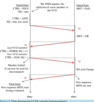
The process of increasing the capacity of a connection by adding new members to a given VCG (OPUk-Xv in OTN) is assumed to be initiated by the Network Management System (NMS). As shown in Figure 3, in an ini-tial state the new member to be added has its CTRL command set to IDLE, since it is not yet a member of the VCG, its SQ number set to the maximum value supported and its MST value set to FAIL. In order to increase the connection capacity the NMS sends a request to the source node for the addition of a new member to the VCG. As a result the following operations take place:
1) The source node generates and transmits an MFAS multiframe, where the CTRL word of the member to be added to the VCG is changed from IDLE to ADD, as an indication to the destination node that the correspondent member is going to be added, together with the new assigned SQ (higher than the previous maximum used SQ). This corresponds to the time to generate and transmit an MFAS multiframe plus the time of its propagation to the destination node
(
2tMFAS+td)
.2) After the destination node having received the CTRL = ADD it sends back an MST multiframe with the status of the new member changed to OK. Thus the delay of this action is the time needed to transmit an MST multiframe plus the time of its propagation to the source node
(
tMST+td)
. [image:5.595.143.485.648.723.2]3) Once the source receives this acknowledgment it generates and transmits a new MFAS multiframe with the new member added. The new member has now its CTRL set to EOS and its SQ assigned, so the decoder can know the correct order of the members when they arrive to destination node. This action takes the time to gener-ate and transmit an MFAS multiframe plus the time of its propagation to the destination node
(
2tMFAS+td)
. In this analysis it is considered that if a new CTRL code is to be inserted while a given MFAS multiframe is being transmitted, the new control code can only be inserted after finishing the multiframe transmission, whence it is used(
2tMFAS)
in the calculations [12].Table 2. MFAS and MST multiframe duration.
OPU1 OPU2 OPU3
OPUk
t 48.971 µs 12.191 µs 3.035 µs
MFAS
t 12.537 ms 3.121 ms 0.777 ms
MST
Figure 3.Time diagram for LCAS capacity increase process.
4) When the destination node receives the new member sequence, with the new member added, it sends back the RS-Ack bit changed, in an MFAS multiframe, as an indication that now it has knowledge of the new se-quence. The time needed for this operation is the time of transmitting the MFAS multiframe plus the time of its propagation to the source node
(
tMFAS+td)
. The addiction of the new member to the OPUk-Xv is then con-cluded.Hence, the overall time delay corresponding to the capacity increase operation is given by:
add 5MFAS MST 4d
D = t +t + t . (2)
Neglecting the propagation and the node delay the total delay time to add a new member to a VCG is then 64.252 ms for OPU1, 15.995 ms for OPU2 and 3.982 ms for OPU3.
3.3. Connection Capacity Decrease
In an initial state the member to be removed from the OPUk-Xv has its CTRL set to NORM or EOS (if it is the member of the VCG with highest SQ), its SQ set to “i”, and its MST set to OK. In order to decrease the connec-tion capacity the NMS sends a request to the source node for the removal of that member from the VCG. As a result the following operations (see Figure 4) take place:
1) The source node generates and transmits an MFAS multiframe with the CTRL word of the member to be removed changed from NORM or EOS to IDLE. Besides, if the member to be removed is the last member of the VCG, the CTRL word of the previous member is changed from NORM to EOS and its SQ is kept unchanged. If the member to be removed is not the last member of the VCG, the SQ numbers of all following active members are decremented by one and their CTRL words are kept unchanged. This corresponds to the time of generating and transmitting an MFAS multiframe plus the time it takes to reach the destination node
(
2tMFAS+td)
.2) After receiving CTRL = IDLE the destination sends an MST multiframe with the status of the member to
t
dt
dt
dMST = OK
Last VCG member:
CTRL = NORM; SQ = i-1
New VCG member:
CTRL = EOS; SQ = i
RS-Ack Change CTRL = ADD
SQ = min_not_used Initial State CTRL = IDLE
SQ = max
Initial State MST = FAIL
Member Added It can now be used for
data transport
Final State New sequence MSTs start
beeing evaluated
New sequence MSTs are sent The NMS requires the
addiction of a new member to the VCG
t
dFigure 4. Time diagram for LCAS capacity decrease process.
be removed as FAIL, as an indication of its acknowledgment of the member removal, and the RS-Ack bit changed for that member, as an acknowledgment of the new sequence in the VCG. Thus the delay of this action is the time needed to transmit an MST multiframe plus the time of its propagation to the source node
(
tMST+td)
. The removal of the member from the VCG is then concluded.Thus, the overall capacity decrease operation delay is given by:
rem 2MFAS MST 2d
D = t +t + t . (3)
As a consequence, the total time required to remove a VCG member, when the propagation and the node de-lay are neglected, is 26.641 ms for the OPU1, 6.632 ms for the OPU2 and 1.651 ms for the OPU3.
3.4. Fault Recovery Time
In the presence of a network failure the first step of the recovery process consist in removing the failed member from the VCG. This process involves the following steps (see Figure 5):
1) The destination node detects a failure in a working VCG member in time instant tf
(
tf ≤td)
.2) The destination node removes the failed member from the payload reassembly process and reports the fail-ure to the source by changing its status to MST = FAIL. The delay of this action is then the time needed to transmit an MST multiframe plus the time required to reach the source node
(
tMST+td)
. Note that for a certain period of time the re-assembled payload in the destination side will be harmed, since the traffic is still sent by the source in all the pre-fault members of the VCG.3) When the source node receives MST = FAIL, it notifies the NMS about the detected failure and generates and transmits a new MFAS multiframe with the CTRL word changed to DNU and at the same time stops putting data on the payload area of the failed member. Once the code CTRL = DNU arrives to the destination node, the removal process is complete, and the payload of the VCG is now error free. Thus the delay of this action is the time required to generate and transmit an MFAS multiframe plus its propagation time
(
2tMST+td)
As acon-sequence the maximum fault-recovery time can be described as:
rec 2MFAS MST 4d
D ≤ t +t + t . (4)
Neglecting the contribution of the time required to detect the failure
(
≤td)
, one concludes that the recovery time given by (4) is exactly the same as the time required to the remove a VCG member (3).In protection schemes based on the “degraded service”, the fault recovery time is given by Equation (4). However, in protection schemes that rely on the existence of protection/backup resources the calculation is dif-ferent. These schemes require the pre-provision of additional capacity by adding backup members to the VCG in addition to the working members, as a way to protect the last ones. The backup members do not carry any traffic
t
dt
dMST = FAIL RS-Ack Change CTRL = IDLE
SQ = max Initial State CTRL = NORM/EOS
SQ = i
Initial State MST = OK
Removal detected
Member no longer carries data
Final State The member is
removed
The NMS requires the removal of a member from
the VCG
Figure 5. Time diagram for LCAS failed member removal.
during normal operation and to guarantee that they are not used by the destination side in the reassembly process their CTRL status is set to be DNU. Therefore, the fault recovery time in this case, besides the time required for detecting and notifying the failure of a working member, also include the time to activate the backup capacity. The first time includes the steps 1) and 2) of the previously described recovery process, while activating the backup members involves the following actions (see Figure 6).
3) After receiving the notification of a member failure the source node notifies the NMS about it and changes the CTRL field of the backup member from DNU to EOS or NORMAL, and the CTRL field of the failed mem-ber from EOS or NORMAL to DNU. The SQ nummem-bers are also rearranged. This new coding takes the time
(
2tMFAS+td)
to reach the destination side.4) The destination node detects CTRL = EOS (or NORMAL) for the backup member and consequently will start to transmit MST = OK. Remember that the failed member is already transmitting MST = FAIL. The time taken by this action is
(
tMST+td)
. Once the source receives MST = OK the traffic previously transmitted on the failed member is switched to the backup member and the recovery process ends. Assuming that the time re-quired by the source to switch the traffic is negligible, the fault recovery time of the described protection scheme reduces to:pro 2MFAS 2MST 4d
D ≤ t + t + t . (5)
when the propagation and node delay are not taken into account the fault recovery time is 28.208 ms for the OPU1, 7.022 ms for the OPU2 and 1.748 ms for OPU3.
The ITU-T Recommendation G.841 [17] indicates that in NG-SDH/SONET networks based on ring protec-tion, for a ring with a perimeter of less than 1,200 km, the switching completing time for a single failure must be less than 50 ms. For a distance of 1,200 km, the propagation time is 6 ms. In this case, neglecting the node la-tency, we conclude that the worst case fault recovery time is 52.208 ms for the OPU1, 31.022 ms for the OPU2 and 25.748 ms for OPU3, showing that for the OPU2 and OPU3 the values are well below the requisite of the typical value of 50 ms.
4. Simulation Results
The methodology presented in the previous section is used here to evaluate the time delays of the LCAS opera-tions in different OTN networks. For sake of comparison, the time delays for NG-SDH/SONET networks are also evaluated using the results presented in [12]. To obtain the propagation delays the shortest-path between each source-destination node pair was computed using the Dijkstra algorithm.
t
dt
dMST = FAIL
CTRL = DNU SQ = max
Initial State MST = OK
Failure detected
The NMS is notified about the detected failure
Failure
time time
Initial State CTRL = NORM/EOS
SQ = i
Final State The member no longer
carries data
t
dIn our analysis, we considered three network topologies: Figure 7(a) the 24-node North American backbone network (UBN), which has 42 bidirectional links and all links are shorter than 3,000 km, Figure 7(b) the 19-node European Optical Network (EON) with 36 bidirectional links, and the longest link is about 2,000 km,
and Figure 7(c) the Pan-European test network (COST 239), which comprises 11 nodes and 26 bidirectional
links, and all links are shorter than 1,000 km (the number on each link represents the length in km). In our study it was computed the maximum and the mean delay related to LCAS operations in each network for both NG-SDH/SONET and OTN technologies. The maximum LCAS delays were computed using the shortest path between the two farthest network nodes, while the mean LCAS delays require the knowledge of the mean value of the shortest-paths computed between all network node pairs.
The results obtained for the time delay introduced by LCAS are shown inFigure 8(a)for the UBN network,
Figure 8(b) for the EON network andFigure 8(c)for COST 239network. It was considered the scenarios where
[image:9.595.150.490.249.550.2]connection capacity increases, connection capacity decreases, and a protection switching is performed between a failed working member and a backup member. For the NG-SDH/SONET networks both the Low Order VCAT
Figure 6. Time diagram for LCAS traffic switching from failed member to backup member.
[image:9.595.95.538.574.708.2](a) (b) (c)
Figure 7.Physical topology of (a) UBN; (b) EON and (c) COST 239 network.
t
dt
dFailed Member: MST = FAIL
Failed Member: CTRL = DNU; SQ = max;
Backup Member: CTRL = NORM/EOS; SQ = i
Initial State
Failed Member: MST = OK
Backup Member: MST = FAIL
Failure detected
The NMS is notified about the detected failure
Failure
time time
Initial State
Failed Member: CTRL = NORM/EOS ;SQ = i
Backup Member: CTRL = DNU; SQ = n
The failed member no longer carries data
t
dBackup Member: MST = OK
Final State Data previously on the failed
member is switched to the backup member
t
d 11 12 13 14 15 16 17 18 19 20 21 22 23 24 1 2 3 4 5 7 6 8 9 10 6 8 12 16 5 11 3 1 4 13 7 9 19 14 17 18 10 15 2 2 5 10 4 1 3 11 8 97 576 6
594
794
752
1000 1000 1000 1000 1000
52
Figure 8. LCAS delays in (a) UBN; (b) EON and (c) COST 239 network.
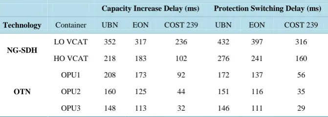
(LO VCAT) for VC-11, VC-12 and VC-2 concatenated containers, and High Order VCAT (HO VCAT), for VC-3 and VC-4 concatenated containers [18] are considered.Table 3 emphasizes the maximum LCAS time de-lays for capacity increase and protection switching, since they are the most critical ones.
The most obvious result is the significant difference between time delays in NG-SDH/SONET networks for LO VCAT and HO VCAT signals, being the latter greatly smaller. This difference comes from the fact that the duration of LO VCAT and HO VCAT frames is 500 µs and 125 µs, respectively [18], which impacts the dura-tion of the multiframes used in the LCAS analysis.
In OTN networks this delay is even more reduced, since the frame durations are smaller than in NG-SDH/ SONET networks. Thus, this becomes immediately an advantage of OTN technology.
In OTN networks the impact of the propagation delay of the messages exchanged between the source and destination nodes is more relevant than it is in NG-SDH/SONET networks, since the OPUk frames duration is significantly smaller than the VC-n frames duration. With k= 1 the delay of increasing or decreasing an OPU1- Xv connection capacity is similar to the delay of increasing or decreasing, respectively, the capacity of an HO VC-n-Xv1 connection. However, for higher values of k the delay of LCAS operations decrease substantially, since the multiframe duration also decreases. Regarding to the operation of switching traffic from a failed member to a previously provisioned backup one, the fact of using an OPU1-Xv instead of an HO VC-n-Xv leads to a delay reduction of approximately half.
In all the analyzed scenarios the operation of increasing the link capacity takes more time than the inverse op-eration, because the handshaking procedure between the source and the destination nodes requires more steps. Furthermore, the difference between the time delays corresponding to these two operations is larger in OTN networks. This is due to the fact that the duration of the MFAS multiframe impacts more the first operation than
0 100 200 300 400 500
VC-11,12,2 VC-3,4 OPU1 OPU2 OPU3
D
re
la
y (m
s)
(a) UBN
Increase (Max) Increase (Mean) Decrease (Max) Decrease (Mean)
Switching (Max) Switching (Mean)
0 100 200 300 400 500
VC-11,12,2 VC-3,4 OPU1 OPU2 OPU3
D
ela
y
(
ms
)
(b) EON
Increase (Max) Increase (Mean) Decrease (Max) Decrease (Mean)
Switching (Max) Switching (Mean)
0 100 200 300 400
VC-11,12,2 VC-3,4 OPU1 OPU2 OPU3
D
ela
y
(ms
)
(c) COST239
Increase (Max) Increase (Mean)
Decrease (Max) Decrease (Mean)
Switching (Max) Switching (Mean)
Table 3.Maximum LCAS time delay for capacity increase and protection switching (ms).
Capacity Increase Delay (ms) Protection Switching Delay (ms)
Technology Container UBN EON COST 239 UBN EON COST 239
NG-SDH
LO VCAT 352 317 236 432 397 316
HO VCAT 218 183 102 276 241 160
OTN
OPU1 208 173 92 172 137 56
OPU2 160 125 44 151 116 35
OPU3 148 113 32 146 111 29
the second one (see Equations (2) and (3)) and this duration is much larger than the duration of the MST multi-frame, contrary to what happens in the NG-SDH/SONET networks, where the MST multiframe is longer than the multiframe used for the MFI control [18]. For the same reason, the operation of protection switching from one member to another is quite large in NG-SDH/SONET since the destination node transmits two MST multi-frames to the source node. As for OTN, this operation’s delay is similar to the capacity increase delay, since the propagation time has a major impact in the overall operation delay and the number of multiframes exchanged in both cases is equal. Note, for example, that in COST 239 network we can accomplish with an OPU3-Xv a delay of 29 ms, while in a NG-SDH/SONET networks we get no less than 160 ms.
The multiframe delays are constant for each LCAS operation and each VC-n-Xv or OPUk-Xv. Therefore, de-lays suffered during the process of dynamically allocating or freeing bandwidth vary with the distance between network nodes. Hence, LCAS operation delays are network topology dependent.
The UBN network, which presents longer path distances, naturally suffers bigger delays and, as a conse-quence, the contribution of the propagation delay to the LCAS delay is stronger than, for example, in the COST 239 network. The maximum distance between two nodes in the latter network is 1,386 km. This leads to a maximum propagation delay around 36 ms, for increasing the connection capacity. For the UBN network the maximum distance between network nodes goes up to 7,200 km leading to a maximum propagation delay of about 144 ms.
5. Conclusion
In this paper, we have explored the application of VCAT/LCAS techniques to provide dynamism in the context of OTN networks. A detailed explanation about the procedures used to resize the capacity of the connections is presented and the time-delays associated with the process are computed. A comparison with NG-SDH/SONET networks is also provided. It is shown that the resizing operations in OTN networks are faster than in NG-SDH/ SONET networks and the speed of the process increases when we move from OPU1-Xv connections to OPU3- Xv connections. For example, for the first type of connection the maximum time delay obtained in all the refer-ence networks considered was about 200 ms, while for the second one the maximum delay is reduced to about 150 ms. For the sake of comparison, the worst results for NG-SDH/SONET networks were about 220 ms and 350 ms, for HO-VCAT and LO-VCAT, respectively. Our results have also highlighted the interest of applying the VCAT/LCAS techniques as a way to improve resilience: by adding a backup member to protect a working member in a VCG we showed that using OPU3-Xv connections it is possible to recover from a member failure in about 25 ms, in a scenario where the NG-SDH/SONET standards define a maximum value of 50 ms.
References
[1] Gumaste, A. and Krishnaswamy, N. (2010) Proliferation of the Optical Transport Network: A Use Case Based Study.
IEEE Communications Magazine, 48, 54-61. http://dx.doi.org/10.1109/MCOM.2010.5560587
[2] Carrol, M., Roese, J. and Ohara, T. (2010) The Operator’s View of OTN Evolution. IEEE Communications Magazine,
48, 46-52. http://dx.doi.org/10.1109/MCOM.2010.5560586
[3] ITU-T Rec. G.709 (2009) Interfaces for the Optical Transport Network (OTN).
[5] ITU-T Rec. G.7042/Y.1305 (2006) Link Capacity Adjustment Scheme (LCAS) for Virtual Concatenated Signals.
[6] Bernstein, G., Caviglia, D., Rabbat, R. and Van Helvoort, H. (2006) VCAT/LCAS in a Clamshell. IEEE
Communica-tions Magazine, 44, 34-36. http://dx.doi.org/10.1109/MCOM.2006.1637944
[7] Santos, J., Pedro, J., Monteiro, P. and Pires, J. (2011) Optimized Routing and Buffer Design for Optical Transport Networks Based on Virtual Concatenation. Journal of Optical Communications and Networking, 3, 725-738.
http://dx.doi.org/10.1364/JOCN.3.000725
[8] Acharya, S., Gupta, B., Risbood, P. and Srivastava, A. (2004) PESO: Low Overhead Protection for Ethernet over SONET Transport. IEEE Infocom 2004, Hong Kong. http://dx.doi.org/10.1109/INFCOM.2004.1354491
[9] Roy, R. and Mukherjee B. (2008) Degraded-Service-Aware Multipath Provisioning in Telecom Mesh Networks. OFC/
NFOEC 2008, San Diego, 24-28 February 2008. http://dx.doi.org/10.1109/OFC.2008.4528661
[10] Huang, S., Martel, C. and Mukherjee, B. (2011) Survivable Multipath Provisioning with Differential Delay Constraint in Telecom Mesh Networks. IEEE/ACM Transactions on Networking, 19, 657-669.
http://dx.doi.org/10.1109/TNET.2010.2082560
[11] Ou, C., Sahasrabuddhe, L., Zhu, K., Martel, C. and Mukherjee, B. (2006) Survivable Virtual Concatenation for Data over SONET/SDH in Optical Transport Networks. IEEE/ACM Transactions on Networking, 14, 218-231.
http://dx.doi.org/10.1109/TNET.2005.863462
[12] Han, D., Li, X. and Gu, W. (2006) The Impact of LCAS Dynamic Bandwidth Adjustment on SDH/SONET Network.
Journal of Optical Communications, 27, 317-320. http://dx.doi.org/10.1515/JOC.2006.27.6.317
[13] Pedro, J., Santos, J. and Pires, J. (2011) Performance Evaluation of Integrated OTN/DWDM Networks with Single- Stage Multiplexing of Optical Channel Data Units. ICTON 2011, Stockholm, 26-30 June 2011.
http://dx.doi.org/10.1109/ICTON.2011.5970940
[14] Schulzrinne, H., Casner, S., Frederick, R. and Jacobson, V. (2003) RTP: A Transport Protocol for Real-Time Applica-tions. RFC 3550.
[15] Bernstein, G., Caviglia, D., Rabbat, R. and van Helvoort, H. (2011) Operating Virtual Concatenation (VCAT) and the Link Capacity Adjustment Scheme (LCAS) with Generalized Multi-Protocol Label Label Switching (GMPLS). RFC 6344.
[16] Das, S., Parulkar, G., Singh, P., Getachew, D., Ong, L. and McKeown, N. (2010) Packet and Circuit Network Conver-gence with Open Flow. OFC/NFOEC’10, San Diego, 24-28 March 2010.
[17] ITU-T Rec. G.841 (1998) Types and Characteristics of NG-SDH Network Protection Architectures.
![Figure 1. OPUk-Xv frame structure (adapted from [3]).](https://thumb-us.123doks.com/thumbv2/123dok_us/8174258.808782/3.595.143.485.436.652/figure-opuk-xv-frame-structure-adapted-from.webp)
![Figure 2. OPUk-Xv virtual concatenation overhead (adapted from [3]).](https://thumb-us.123doks.com/thumbv2/123dok_us/8174258.808782/4.595.114.517.479.705/figure-opuk-xv-virtual-concatenation-overhead-adapted.webp)