© 2017, IRJET | Impact Factor value: 5.181 | ISO 9001:2008 Certified Journal | Page 1862
Power Saving Industrial Plant
Badri Narayan Mohapatra
1, Aishwarya Dash
2, Dhiraj Kumar Chaubey
31
Assistant Professor, ETC department of OCEM, Bhubaneswar, Odisha, India
2Assistant Professor, ETC department of OCEM, Bhubaneswar, Odisha, India
3
Final year B.Tech student of ETC department in OCEM, Bhubaneswar, Odisha, India
---***---Abstract -
The article is based on power saving industrial plant. The bulky electrical equipments used in industrial purpose require high power to be driven. Again their maintenance and safe running process requires some more power consuming equipments to be driven simultaneously. The power requirement to drive these heavy electrical loads can neither be avoided nor be reduced due to their high wattage and heavy duty, but by making some changes to the industrial infrastructure the efficiency can be improved. In this paper some useful methods has been suggested that can be implemented in the industrial plants to run them in energy saving mode. There are various industrial sectors which undergoes various types of energy losses. Hence considering the different ways of energy losses, different solutions can be followed. Here we are representing particularly three different cases of energy losses those are generally occur in industrial plants and corresponding energy saving models are suggested.Key Words: Chemical absorption for CO2capture,Energy-saving mechanism, Exergy destruction, Waste heat recovery Coal-fired power plant ,compression .
1.INTRODUCTION ( Size 11 , cambria font)
Industries are increasing day by day and all of them involve the consumption of high amount of input energy. But according to law of conservation of energy,”Energy can neither be created nor be destroyed; it can only be converted from one form to another.”From this statement it is obvious that the total amount of energy available is limited but this limited amount of energy is to be used to serve for the increasing industrial requirement. So during the planning of an industrial plant it is very much essential to calculate the energy efficiency of that plant. Basically the hardware industries such as power plant implements bulky devices which requires a high amount of input energy to be driven. Also they involves high amount of energy loss in form of heat, sound or any other form of mechanical energy. The energy loss due to moving parts, frictional loss, heat loss etc. cannot be avoided in hardware industries. Such a high amount of energy involvement in an industry reduces its energy efficiency and it is always a trending research how to minimize the loss to increase the performance of the plant. Hence now a days almost all the industrial plants prefer to incorporate an energy saving mode of operation.
2. DIFFERENT METHODS OF ENERGY SAVING
Industrial plants are having a variety of structures involving a variety of equipments depending upon their purpose. Accordingly the causes of energy loss also differ. So obviously the methods used to minimize the loss must be different for different plants. Hence there are a number of ways used to incorporate power saving method.
2.1 Energy Saving By CO2 Absorption Process
This method is incorporated in those plants where high amount of CO2 emission takes place (i.e. basically in coal-fired power plant). CO2 has an ability to capture the heat. Hence most of the loss in this plant is caused by this excessive amount of CO2 emission. The chemical process involved in the plant for which the CO2 emission occurs must not be avoided but the only method can be adapted to minimize the loss is CO2 absorption.
The commonly used absorbents for the chemical absorption of CO2 are amine based solutions (mono ethanol amine (MEA) and di-ethanol amine (DEA)) and potassium carbonate solutions (K2CO3)[1,2]. But again another problem is that a high amount of energy is consumed during the re-extraction of the absorbents from the steam which reduces the efficiency up to a remarkable point. To compensate this reduction in efficiency some absorbent improvement methods can also be adapted. They are addition of activator to the absorbent to increase its rate of absorption, optimization of some parameters like lean solvent loading, amine solvent concentration, and the stripper operating pressure etc [5]. Also by system integration, two systems can be combined so that the waste heat from the stripped steam and CO2 compression process can be recovered to preheat the feed water [6].
From a theoretical analysis the energy and exergy balanced equation is given by
Hflue,g + Qsteam + Wwork + Hwater = Hflue,e + HCOS +QC1 + QFl + QI−Cl ... (1) Hflue,g- Enthalpy of the inlet flue gas
Hwater- Enthalpy of the supplemental water Hflue,e- - Enthalpy of the ejected flue gas
HCOS-Enthalpy changed by net input and output stream QCI- Heat lost in lean solvent cooler
QFI- Heat lost in stripped vapour flasher
© 2017, IRJET | Impact Factor value: 5.181 | ISO 9001:2008 Certified Journal | Page 1863 MSW & HEC- Exergy change related to separation of
CO2-G from flue gas
MCW- Minimum CO2 compression work neglecting water Water condensation
EDCI- Exergy destruction in lean solvent cooler EDFI- Exergy destruction in flasher
EDI-CI- Exergy destruction in the inter cooler EDCM&PM- Exergy destruction in the compression Process
[image:2.595.313.551.102.523.2]A simple blueprint of the proposed plant has been shown in the block diagram given in fig.1. Here the inputs to the plant are input work supply, which is given to gas compressor and the input heat supply which is given to disrober.
Fig -1: Block Diagram of CO2 absorption Process
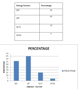
Table -1: Energy Distribution percentage
Energy Factors Percentage
QCI 36
QFI 45
QI-CI 15
HCOS 4
[image:2.595.40.279.288.399.2]Chart -1: Energy Distribution Chart
Table -2: Exergy Distribution percentage
Exergy Factors Percentage
EDAb&Ds 25
MSW&HEC 19
MCW 15
EDCI 9
EDFI 20
EDI-CI 8
EDCM&PM 4
Chart -2: Exergy Distribution Chart
2.2 Energy Saving in Compressed air System
Basically the industries of glass and ceramic production, refining processes and automotive/aerospace manufacturing suffers from high amount of energy loss due to compressed air systems involved in the plants. It has been found by research that up to 50% of the total electricity produced is consumed by the industries and up to 20% of this energy is consumed only [3] . This loss can be reduced by reducing the work done during the compression process which can be achieved by cooling the air adiabatically [7,8]. To analyse how to use this type of system in power saving mode, here the best example can be considered as Gas Engine driven Heat Pump (GEHP) system.
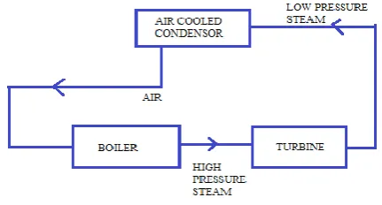
[image:2.595.37.291.447.735.2]© 2017, IRJET | Impact Factor value: 5.181 | ISO 9001:2008 Certified Journal | Page 1864 condensation. Here the discussion is focused on air cooled
compression. The below fig.2represents a simple block diagram of air cooled condenser. Here the low pressure steam exhausted from the turbine flows towards the cooling condenser through a bundle of tube then it is condensed by the air flow of properly designed fan. The main advantage of air cooled condenser is it does not use water to condense the fluid hence also saves water.
PER (Primary Energy Ratio) is the most important factor to be calculated here and the related formula is given by
[image:3.595.303.562.65.243.2]
PER = (Cooling Heat rate + Cylinder Jacket heat rate + Exhaust Heat rate)/Natural gas Heat rate A graph is plotted to show the variation of PER with the varying speed of engine which is shown in chart-3. These data are collected taking the ambient temperature 330C. It has been found from the equation that the relationship is approximately linear.
Fig -2: Block Diagram of air cooled condenser
Table -3: Variation of primary Energy ratio with speed of Engine at ambient temperature 330C.
Speed of Engine in
rpm PER
1200 1.45
1400 1.42
1600 1.38
1800 1.29
2000 1.23
2200 1.15
Chart -3: Variation of PER with respect to speed of Engine Table -4: Energy saving comparison
Comparison factor Electrical Heat Pump GEHP with air cooled condenser
PER 0.92 1.18
Total Primary Energy
1111.4 823.33
2.3 Energy Saving in Industrial Exhausting Fans Exhausting fans are used in industries for cooling purpose or to maintain the temperature rise caused by the excessive amount of heat produced during the running of heavy electrical devices. These exhausting fans require an additional amount of electrical energy to run. So instead of running these fans all the time with the other devices, turning them “ON” only when it is necessary or when the temperature rises more than the threshold value can somehow save the power up to a certain amount. This can be done by implementing an embedded system based control unit which will continuously check the temperature level and automatically turn “ON” the exhausting fan by sending some control instruction when the temperature will rise more than the threshold value and also automatically turn them OFF by another control instruction as the temperature will fall below the threshold value. This type of controlled operating mode of the devices can be indicated as power saving mode of operation.
[image:3.595.55.271.356.472.2]© 2017, IRJET | Impact Factor value: 5.181 | ISO 9001:2008 Certified Journal | Page 1865 not only saves the electricity required to operate the fan but
also the cost of conditioned air that is exhausted unnecessarily.
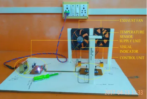
[image:4.595.37.285.301.468.2]A model has been designed to study about the proposed industrial plant. Here a thermister has been used to sense the over temperature. A microcontroller is used to automatically control the exhaust fans. When the thermister will sense the over temperature its resistance will fall down and a small current will pass through it which will go to the microcontroller as an input pulse. By getting this input pulse the control unit sends the output instruction to turn “ON” the fans as per the requirement. When the temperature will gradually fall down, the supply to the fans will be cut down one by one, hence they will be turned “OFF” one by one. It seems that the modules which are hit first by the wind are the coolest and the module with the highest temperature is the point at which the air exits the array [10].
Fig -3: Prototype model for power saving industrial exhausting fan
3. CONCLUSIONS
Industries are consuming the largest part of electricity
produced. The three different cases focused in this
paper are the highest power consuming industrial
sectors. Hence some useful techniques have been
explained here with proper analytical information
about the amount of energy saving.
In CO2 capture process by applying waste heat
recovery and inter cooling integrated system a
considerable amount of energy (i.e. up to 40%) can be
saved. Further improvement in the overall efficiency
needs more analysis on better heat recovery process
and economical implementation of the plant providing
the proposed techniques. In compressed air system the
adiabatic cooling process has been suggested as an
energy saving mode of operation that has been studied
and verified and the required parameters has been
derived regarding its usefulness. The next proposed
idea is to be implemented in the heavy equipment
industries which use large number of exhausting fans
to maintain the temperature during the working period
of the heavy machines. Here the suggested energy
saving model uses the atomization technique by using a
heat sensor and an embedded control unit that
automatically controls the running process of the
exhausting fan. By applying this mechanism the
exhausting fans are being kept in rest for a longer time
as compare to those used in non automated plants,
hence a very large amount of energy is saved. So this
paper is actually aimed to give an overall idea on
energy saving mechanism that can be implemented in
different industrial plant so that we can properly use
the energy and unnecessary power wastage can
beavoided.
REFERENCES
[1] Pellegrini, G., Strube, R., Manfrida, G.,” Comparative
study of chemicalabsorbents in postcombustion CO2capture. Energy” 35 (2010), 851–857.
[2] Rao, A.B., Rubin, E.S.,. “A technical, economic and
environmental assessmentof amine-based CO2capture technology for power plant greenhouse gascontrol. Environ”. Sci. Technol. 36(2002), 4467–4475.
[3] Radgen P, Blaustein E. Compressed air systems in the
European Union. Energy,”Emiss Sav Potential Policy Actions 2001;50e3:66. LOG_X, ISBN 3-932298-16-0.
[4] Gungor A, Tsatasronis G, Gunerhan H, Hepbasli A.
Advanced exergoeconomic analysis of a gas engine heat pump (GEHP) for food drying processes. Energy Convers Manage 2015;91:132–9.
[5] Oyenekan, B.A., Rochelle, G.T.,. “Rate modeling of
CO2stripping frompotassium carbonate promoted by piperazine. Int. J. Greenhouse Gas Control 3,( 2009)121– 132.
[6] Xu, G., Yang, Y.P., Ding Li, J.S.C., Liu Zhang, W.Y.K.,.
Analysis and optimizationof CO2capture in an existing coal-fired power plant in China. Energy 58,( 2013a)117– 127.
[7] Soltani R, Dincer I, Rosen MA. Comparative performance
evaluation of cascaded air-source hydronic heat pumps. Energy Convers Manage,2015;89:577–87.
[8] Carvalho AD, Moura P, Vaz GC, Almeida AT. Ground
source heat pumps as high efficient solutions for building space conditioning and for integration in smart grids. Energy Convers Manage 2015;103:991–1007.
[9] Cui, Xudong, and Fengjun Chang Hongquan Ma.
"Sintering System Exhaust Fan Energy Saving." In Instrumentation and Measurement, Computer, Communication and Control (IMCCC), (2015) Fifth International Conference on, pp. 1489-1492. IEEE.
[10] Hrica, Jonathan, Saurabh Chatterjee, and GovindaSamy
© 2017, IRJET | Impact Factor value: 5.181 | ISO 9001:2008 Certified Journal | Page 1866
BIOGRAPHIES
Badri Narayan Mohapatra has completed B.Tech and M.Tech from BPUT Odisha. His area of research interest is in communication. Currently working as Assistant Professor ETC department in Oxford College Of Engineering, And Management.
“Aishwarya Dash has completed B.Tech from BPUT Odisha. Currently working as Assistant Professor ETC department in Oxford College Of Engineering, and Management. “