© 2017, IRJET | Impact Factor value: 5.181 | ISO 9001:2008 Certified Journal | Page 2690
PERFORMANCE STUDY OF HIGH RISE BUILDING WITH DIAGRID
SYSTEM UNDER DYNAMIC LOADING
Dr.Gopisiddappa
1, M.Divyashree
2,Sindhuja G J
31,2
Associate Professor,Dept.of civil Engineering,PESCE,Mandya,Karnataka,India
3M.Tech Student,Dept. of civil Engineering,PESCE,Mandya,Karnataka,India
---***---Abstract –
Construction of multi-storey building is rapidlyincreasing throughout the world. The diagrid structural system has been widely used for recent tall buildings due to the structural efficiency and aesthetic potential provided by the unique geometric configuration of the system.Diagrid is system of triangulated beams,straight or curved, and horizontal rings that together make up a structural system for a skyscrapers.
Diagrid structure use a lesser amount of structural material in general than conventional structural systems composed of orthogonal members. The structural efficiency of the diagrid system makes the number of interior columns decrease,therefore allowing much flexibility on the plan design.In this journal the concept of diagrid structural system is studied by conducting literature review,then optimum configuration for buildings and optimum angle for diagrid is found out by comparing conventional building with diagrid building with same plan area using ETABS software.
Key Words:Diagrids,Storey Displacement,Inter Storey Drift,Design Base Shear.
1.INTRODUCTION
Tall building or high rise structures construction are more in this era, due to increase in population, economic prosperity and also due to the scarcity of lands high rise structures or tall buildings are recommended. Height is main criteria in this kind of buildings, demand for tall buildings has increased because of increase in demand for business and residential space, advances in constructions, high strength structural elements, materials and also various software like ETABS, Staadpro, etc these are analysis and design softwares have provided development of high rise structures.
In 19th century tall buildings were built in U.S.A but now a days due to people needs tall buildings are constructing every where this leads to sustainable development of society that is “ development that meet meets the expectations and needs of present generation without compromising the ability of future generations to meet their requirements”. Accoeding to studied and published articles in 1980, most of tall buildings were located in America and now recent studies shows that number of tall building and construction process is more in Asian countries, it is of about 32% and 24% in north America and Europe. Generally tall buildings are constructed and used for commercial office buildings, apartments etc.
1.1 OPTIMAL ANGLE
As in the diagrids, diagonals carry both shear and moment.Thus, the angle of diagonals is highly dependent upon the building height.Since the optimal angle of the columns for maximum bending rigidity is 90 degrees and that of the diagonals for maximum shear rigidity is about 35 degrees, it is expected that the optimal angle of diagonal members for diagrid structures will fall between these angles and the building height increases, the optimal angle also increases. Usually adopted range is 60-70 degree.
1.2 OBJECTIVE OF STUDY
Aimed to study the behaviour of tall building without any lateral load resisting system
To examine response of high rise building with diagrid system
An attempt is made to study response of buildings under dynamic loadings( i.e wind and earthquake load)
Diagrid systems are analysed for different angle of an external bracings
Storey shear of all the modals are compared
Storey drift and displacement of all the structures are plotted and results are compared to know responses of these buildings.
2.MODEL GEOMETRY
The details of models are given as follows
Plan dimention-30m*30m
Number of stories-30
Floor to floor height-3m
Number of bays in X-direction-6
Number of bays in Y-directio
Depth of slab-120mm
Beam and column dimentions B1-250mm*450mm
International Research Journal of Engineering and Technology (IRJET)
e-ISSN: 2395 -0056Volume: 04 Issue: 06 | June -2017 www.irjet.net p-ISSN: 2395-0072
[image:2.595.40.540.167.756.2]© 2017, IRJET | Impact Factor value: 5.181 | ISO 9001:2008 Certified Journal | Page 2691 Fig -1: Plan of the linear building
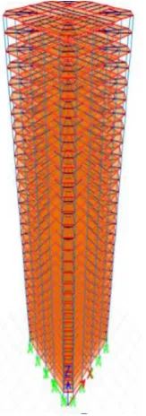
Fig -2: Building 3D view of linear system
Chart-1:Maximum storey displacement for wind, earthquake and responses spectrum cases
Chart-2:Maximum storey drift for wind, earthquake and responses spectrum cases
3. ANALYSIS OF DIAGRID SYSTEM
The details of models are given as follows
Plan dimention-30m*30m
Number of stories-30
Floor to floor height-3m
Number of bays in X-direction-6
Number of bays in Y-directio
Depth of slab-120mm
Floor diaphragm is assumed as rigid
Beam and column dimentions B1-250mm*450mm
B2-300mm*600mm C1-900mm*900mm D1-450mm*450mm
[image:2.595.107.189.304.537.2]© 2017, IRJET | Impact Factor value: 5.181 | ISO 9001:2008 Certified Journal | Page 2692
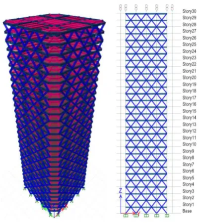
Fig -4:Building 3D view and elevation view of diagrid system with diagonal angle 45 degree
Chart-3:Maximum storey displacement for wind, earthquake and responses spectrum cases
Chart-4:Maximum storey drift for wind, earthquake and responses spectrum cases
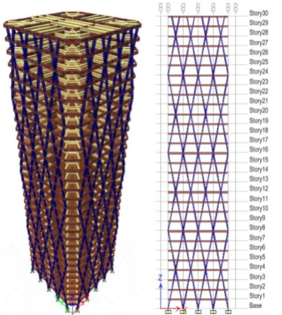
Fig -4:Building 3D view and elevation view of diagrid system with diagonal angle 63 degree
Chart-5:Maximum storey displacement for wind, earthquake and responses spectrum cases
International Research Journal of Engineering and Technology (IRJET)
e-ISSN: 2395 -0056Volume: 04 Issue: 06 | June -2017 www.irjet.net p-ISSN: 2395-0072
[image:4.595.48.253.111.340.2]© 2017, IRJET | Impact Factor value: 5.181 | ISO 9001:2008 Certified Journal | Page 2693
Fig -5:Building 3D view and elevation view of diagrid system with diagonal angle 73 degree
Chart-7:Maximum storey displacement for wind, earthquake and responses spectrum cases
[image:4.595.341.527.111.329.2]Chart-8:Maximum storey drift for wind, earthquake and responses spectrum cases
Fig -6:Building 3D view and elevation view of diagrid system with diagonal angle 75 degree
Chart-9:Maximum storey displacement for wind, earthquake and responses spectrum cases
© 2017, IRJET | Impact Factor value: 5.181 | ISO 9001:2008 Certified Journal | Page 2694
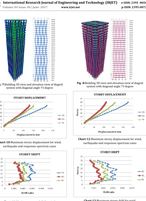
Fig -7:Building 3D view and elevation view of diagrid system with diagonal angle 73 degree
Chart-10:Maximum storey displacement for wind, earthquake and responses spectrum cases
[image:5.595.52.557.547.717.2]Chart-11:Maximum storey drift for wind, earthquake and responses spectrum cases
Fig -8:Building 3D view and elevation view of diagrid system with diagonal angle 73 degree
Chart-12:Maximum storey displacement for wind, earthquake and responses spectrum cases
International Research Journal of Engineering and Technology (IRJET)
e-ISSN: 2395 -0056Volume: 04 Issue: 06 | June -2017 www.irjet.net p-ISSN: 2395-0072
© 2017, IRJET | Impact Factor value: 5.181 | ISO 9001:2008 Certified Journal | Page 2695
4. CONCLUSIONS
The present work consists of analysis of 30 storey linear building and analysis of diagrid systems with different diagonal angles that is 45 degree, 63 degree, 73 degree, 75 degree, 78 degree, 81 degree. The comparison between linear building and diagrid building is carried out. ETABS software is used for modeling and analysis of structure. Analysis results like storey displacement,interstorey drift are presented here.Following are the conclusions inferred from the study.
Framing building without any load resisting system shows highest drift and displacement value as compared to diagrid system
Top storey displacement is less for diagrid system with diagonal angle 63 dgeree
Between the region 63 degree to 75 degree (diagonal angle) diagrid system posses better stiffness, storey drift and storey displacement are less in this region.
REFERENCES
[1] Barry Charnish and Terry Mc Donnel “ the Bow Unique
Diagrid Structural Systems For Sustainable Tall Buildings”,2009
[2] Giulia milana, franco bontempi,pierluigi
olmati,konstantinos gkoumas “Ultimate Capacity Of Diagrid Systems For a Tall Buildings in Nominal Configuration and Damaged State”, Feb 2015
[3] J.Kim, Y. Jum and Y-Ho Lee “Seismic Performance
Evaluation Of Diagrid Systems Buildings”, June 2010
[4] Johan Leonard “Investigation Of Shear-lag Effect In High
–Rise Buildings With Diagrid Systems”, 2005
[5] Khushbu Jania, Paresh V. Patelb “Analysis And Design Of
Diagrid structural system for High Rise Steel Buildings”,Jan 2013
[6] Kyoung sun moon “Structural Design and Construction
Of Complex Shaped Tall Buildings”, 2008
[7] Kyoung –Sun Moon, John E.Fernandez and Jerome J.
Connor “ Diagrid Structural Systems For Tall Buildings : Characteristics and Methodology For Preliminary Design”,2007
[8] Lekshmi Mohan, C.K.Prasad Varma Thampan “
Numerical Moddelling and Evaluation Of Hybrid Diagrid Structures”,June 2015
[9] Mr.Devaraj R,Rajalaxmi M Megadi “Analysis Of Curved
Perimeter Diagrid lateral Systems”, June 2014
[10] Nishith B.Panchal, Dr.V.R Patel, Dr.I.I.Pandy “Optimum
angle of diagrid Strucutural System”, June 2014
[11] Nitish B.Panchal, Dr.V.R. Patel “Diagrid Structural
Systems :Stratergies To Reduce Lateral Forces On high Rise Building “, April 2014
BIOGRAPHIES
Sindhuja.G.J a Mtech student of P.E.S college of Engineering, Mandya,Karnataka, Specilization in in CAD-Structures.