http://dx.doi.org/10.4236/cs.2014.512032
The Neuron as a Controlled Toggle Circuit
John Robert BurgerECE Department, California State University, Northridge, USA Email: [email protected]
Received 9 September 2014; revised 8 October 2014; accepted 21 October 2014
Copyright © 2014 by author and Scientific Research Publishing Inc.
This work is licensed under the Creative Commons Attribution International License (CC BY). http://creativecommons.org/licenses/by/4.0/
Abstract
This paper considers a model of a recursive neuron whose circuit the author finds interesting, not because of its financial possibility, but because of its surprising electrical behavior. Below, a re-cursive neuron is modeled with excitatory and inhibitory triggering, and simulated using Win Spice. This model is shown to be capable of controlled toggling, and so promises energy-efficient, massively parallel computing.
Keywords
Brain Circuits, Neural Circuits, Toggle Circuits, Recursive Neurons
1. The Recursive Neuron
Realistic circuit models of neurons with computer analysis began to appear in mid twentieth century [1]. This early work is now settled science, promulgated in all major neuroscience texts. Its wide publication makes it easy and fun to explore idiosyncrasies and obscure implications of the modeling. Some configurations of interest to electrical scientists, such as the recursive neuron, have been brushed over by neuroscientists, who are mainly interested in molecular biology and biochemistry, not circuitry.
The information in this article is not new, except for point of view. A neuron is viewed here as an electrical device, and not just a conveyor of molecules. Realistic neurons are interesting from a circuits and systems pers-pective and suggest a new direction for circuit theory.
A neuron consists of dendrites, or branches attached to a body, or soma, from which a single axon spreads out to form synapses, or connections to the dendrites of other neurons. Pulses can be triggered in exposed neural membrane, chiefly on dendrites and soma, which are active electrically. Subsequently they propagate along ex-posed membrane without dispersion with soliton-like properties. Compared to the speed of light, about 3 × 108 mm/ms, they are slow, roughly 1 mm/ms, which is not a drawback in a massively parallel biological system.
engineer’s mind, using the models below as a basis. But such imaginings are unintended byproducts.
2. Environment for Neural Pulses
Neurons are elongated biological cells with micrometer dimensions, enclosed in a thin 1 to 5 nm membrane. This membrane has a landscape of transmembrane molecules which, once triggered, form conductive “ion” channels. They subsequently pass sufficient electrical charge to form a substantial, roughly 110 mV amplitude pulse across the membrane. Outside ions such as sodium place positive charge inside the membrane, or other-wise, they draw out negative charge from the interior; concurrently, inside ions such as potassium remove posi-tive charge from the inside so that a definite pulse occurs across membrane capacitance.
In equilibrium, prior to triggering, there is an interior potential of about −70 mV relative to the outside, be-cause of normal exchanges of charges between the inside and outside ions. This potential seems small, but re-sults in a high field across the thin membrane, roughly 140 kV/cm. Lightening in air requires only about 30 kV/cm. As a result, while in equilibrium, membrane molecules are held quite tightly.
But if an external force reduces the voltage across the membrane from −70 mV to about −55 mV, transmem-brane molecules begin to relax, and permit positive charge inside. This further triggers transmemtransmem-brane mole-cules so that a rising pulse is initiated.
Once channels in the membrane are triggered, sodium ions outside the neuron tend to arrive first, mainly since they are smaller and move faster. The fastest of them might actually plough through the channel to directly cap-ture an electron inside the region. When this happens, the interior contains incorrect ions, which must be pumped out later, a process that consumes calories.
The vast majority of ions in a Maxwell-Boltzmann distribution are moving at relatively low speeds, and are expected to meander near (or into the mouth of) a channel at a very low speed. Electrons inside are free briefly, and like a cloud they tunnel everywhere; outside sodium ions may capture interior electrons, thus contributing to positive charge inside. The net result is a rising voltage inside the neuron.
Potassium ions inside the neuron also approach the ion channels but are larger and slower in average speed. They arrive later, and take over fewer channels. The fastest of them may escape from inside the neuron; but any lost potassium must be replaced, which dissipates calories. The vast majority of potassium ions move slowly near the region of the channel, and some of them may capture an electron from the outside. Actions like this bring negative charge into the region and slow the rise of the voltage pulse slightly.
Positive pulse buildup naturally terminates as positive voltage builds up to a peak of about +40 mV. Near this point a strong reversing field tends to trap ions inside the channel, which are held with a time constant; they re-pel other ions away from the channel. Meanwhile, the potassium channels keep working, causing the pulse to be reduced in voltage. Eventually it undershoots to about −90 mV, which is below its rest voltage of −70 mV. The associated electrical stress on the molecules supporting the conductive channels causes them to reset, thus clear-ing and closclear-ing all ion channels. In due course, voltage drifts back to equilibrium at −70 mV. Re-triggerclear-ing is of course possible.
A neural pulse is surely an amazement, and it is an entirely natural process; ideal pulses are relatively efficient because ionic conditions are restored, and voltages have relatively low rates of change, resulting in low charging currents, and low losses. It is not like transistors, in which charge is dissipated in stray resistance during rapid switching, necessitating extra cooling.
3. Simulation of a Neural Pulse
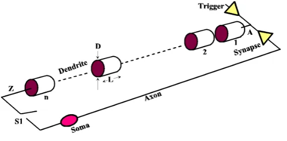
Figure 1. Model of a dendritic path (S1 is a simulation switch to close the loop).
length in a scalable model, but here each segment is assigned a fixed diameter D = 1 × 10⁻⁴ cm, and length L = 0.1 cm.
Consider a single segment. To facilitate a computerized analysis, realistic parameters are assumed as in Table 1. These parameters are only estimations, but provide a reasonable neural pulse.
Table 2 summarizes equations for computing electrical parameters from physical parameters.
A given segment has the circuit model shown in Figure 2. Series resistance R1 is high, roughly 200 M be-cause the low cross sectional area. Membrane loss RLOSS1 is fairly high, about 106 M, because a membrane is basically extremely thin and is slightly conductive Table 3 lists the parameters used in this model.
This model is piecewise linear in that sodium current is triggered to begin when nodal voltage is −55 mV, but is cut off when voltage reaches +40 mV. Potassium current is also triggered at −55 mV but is not cut until vol-tage falls back to −90 mV. These properties were simulated using controlled volvol-tage sources in WinSpice to create hysteresis loops, the outputs of which drive inputs to controlled current sources. Details are published elsewhere [3].
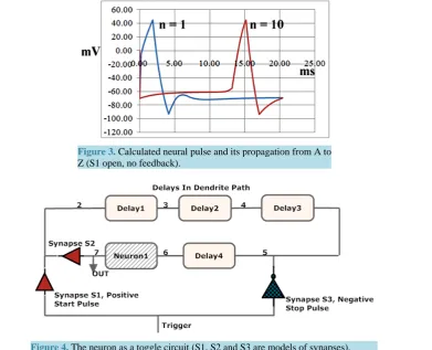
Under this model a pulse appears as in Figure 3. This is reasonably close to what is physically observed ex-perimentally. A pulse in segment 1 soon triggers a pulse in segment 2 when membrane potential reaches −55 mV. Pulses propagate by triggering new identical pulses in resting adjacent segments, appearing to propagate without attenuation or dispersion. After about 15 ms in this model a pulse appears in segment n = 10, which is a distance of 1 cm.
There are several interesting features of such neural pulses. For instance, it is found by simulation that when a pulse reaches an unterminated end of a dendrite, it disappears. But if it encounters a capacitive load of sufficient magnitude, as it would at the central body of a neuron, it is reflected, giving a back propagation. Back propagat-ing pulses sometimes encounter an approachpropagat-ing pulse, and when they collide, both pulses are annihilated. This cuts the rate of arriving pulses in half.
4. A Natural Toggle Element
A neuron whose output synapses back to its own input is capable of cycling a single pulse indefinitely, as has been studied by simulation [3]. A single pulse comes from a physically distinctive weak synapse, or alternatively, via a special circuit that converts a pulse burst into a single pulse.
Any given neuron that feeds back on itself can serve as a toggle, delivering either a rest potential, or a stream of regular neural pulses. Combinational logic also could be used to implement a toggle, but at the expense of ex-tra neurons.
Membrane Capacitance 1 uF/cm2
Membrane Conductance 0.3 mS/cm2
Internal Resistivity ρ 15.7 Ω-cm
Table 2. Equations.
L = 1 mm = 0.1 cm;
D = 1 u = 1.0 e-4 cm;
ACS = π(D/2)2;
R1 = ρL/ACS =15.7 L/ACS Ω;
ASIDE = π DL;
C1 = 1 uF/cm2 ASIDE;
RLOSS1 = 1/(0.3 e-3 ASIDE) Ω;
INa1 = 0. 06725 mA/cm2 ASIDE;
IK = 0.0304 mA/cm2 ASIDE
Table 3. Simulation parameters.
R1 = 200 M
C1 = 31.4 pF
RLOSS1 = 106 M
INa1 = 2.11 nA
IK1 = 0.955 nA
Figure 2. Circuit model of a segment.
Synapses S1, S2 are excitatory synapses modeled with positive charge injection. Synapse S3 is an inhibitory synapse modeled with negative charge injection. The plan is to apply a trigger simultaneously to both synapses S1 and S3 to achieve a toggle neuron.
Figure 3. Calculated neural pulse and its propagation from A to Z (S1 open, no feedback).
Figure 4. The neuron as a toggle circuit (S1, S2 and S3 are models of synapses).
circuit is easily converted into a set-clear latch, if needed, although clearing is not logically reversible. Toggling is logically reversible with advantages because information is not destroyed. Note that the rate of pulse cycling can be reduced, if desired, by changing the length of the delay path, or alternately by changing ionic conditions to modify delay properties.
Synapse S2, which closes the loop, is modeled with WinSpice code as in Table 4.
This simulates a synapse between a termination on an axon and a receptor on a dendrite. Node 3 is the input; node 2 is the output. The input between nodes 3 and 0, is referenced to a rest voltage of −70 mV, applied at node 1 in this subcircuit. In addition, a load resistor is used to represent a realistic receptor at the output, and is placed between node 2 and node 1.
5. Controlled Toggling
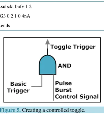
A controlled toggle is one that toggles if and only if one or more control signals are true. A controlled toggle may be implemented as in Figure 5 with the aid of a neural AND gate [3]-[5].
Controlled toggles possess computational possibilities, and may be important to mental processing. In partic-ular, controlled toggling has capability for massively parallel computing, and could serve for the prioritization of mental images and recalls. Logical reversibility and efficiency in controlled toggles are well known advantages [4].
6. Method of Triggering
Triggering depends on charging membrane capacitance from rest (−70 mV) up to a threshold at −55 mV. Trig-gering in this simulation stems from a given source with an amplitude of 1 V and a pulse width of 0.4 ms for ex-citatory, and similarly for inhibitory pulses. Longer triggers are more effective but were unnecessary in this work. Voltage pulses were converted into a nanoampere-range current pulse using a transconductance element.
[image:5.595.190.413.86.213.2].subckt bufv 1 2
G3 0 2 1 0 4nA
[image:6.595.213.382.205.391.2].ends
Figure 5. Creating a controlled toggle.
A negative charge injection to node 5 conducts with attenuation to all other nodes and helps to stop cycling pulses no matter where they are. The negative charge injector has WinSpice code as in Table 6.
Since input voltage (Node 1) to this generator is 1 V, 0.4 ms, this amounts to 25 nA, 0.4 ms from the current source. The pulse is made negative by the order of the outputs at nodes 0, 2 which is reversed to 2, 0 in the vol-tage-controlled current source (G3).
The system of triggering in the given toggle element depends on positive charge injection at one point and simultaneous negative charge injection at another well-chosen point in the loop. Pulse cycling will not start if negative injection is applied too close to the positive pulse point. For instance, cycling pulses will not stop in this circuit if negative injection is applied to nodes 3, 4 or 7 in Figure 4, but on and off toggling occurs normally if negative injection is applied to Nodes 5 or 6.
7. Simulation Results
A combination of events controls pulses in a recursive neuron. Concerning magnitude of the positive trigger pulse, appropriate triggering was found to occur from roughly 2 nS to 5 nS. Below 2 nS a pulse could not be triggered because voltage did not build up to a threshold for triggering; above about 5 nA a single narrow pulse occurred, but would not propagate. This is because the peak at +40 mV was reached too fast, which did not al-low time enough for capacitance in the next segment to charge up to its −55 mV threshold.
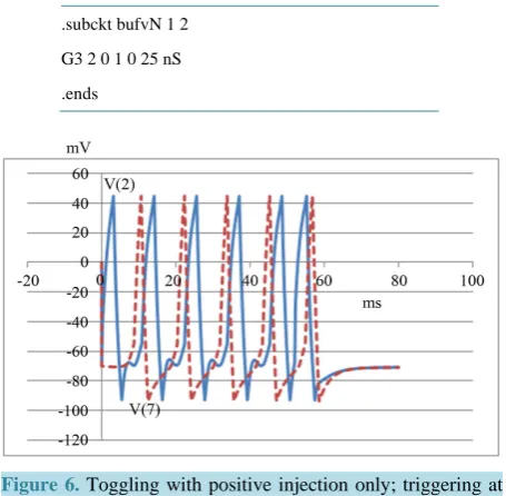
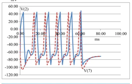
It may be noted that if the negative injection is totally removed from the simulation, this circuit continues to function as a toggle element under certain conditions (Refer to Figure 6).
Here a pulse train (Node 2 in Figure 4, solid blue line) is triggered at zero. Another trigger at about 52 ms rises up to interfere with the output pulse burst (Node 7 in Figure 4, dashed red line) and prevents further prop-agation of pulses.
Table 6. Synapse (negative charge injection).
.subckt bufvN 1 2
G3 2 0 1 0 25 nS
[image:7.595.185.413.99.322.2].ends
Figure 6. Toggling with positive injection only; triggering at zero and 52 ms.
Toggling to false occurs if a cycling pulse arrives while positive injection is occurring. Voltage is then forced to rise too fast; as a result the pulse then begins to fall before the next segment can charge to a triggering thre-shold. The net result is that there is not enough charge transferred to the next segment (labeled Delay1 in Figure 4) to cause it to trigger. Pulse cycling thus stops.
When using negative injection (representing an inhibitory synapse), the delays between triggers for toggling are far less critical. Using a 25 nA negative pulse, toggling worked at all tested trigger delays in the range 20 to 80 ms (Refer to Figure 7).
Here a circulating pulse train is triggered at zero. A significant negative charge is injected after 60 ms that eventually stops all pulses from cycling, including the original pulse, as well as the new pulse at 60 ms. The solid blue line is the waveform at the point of triggering, Node 1 in Figure 4; the dashed red line is the output pulse burst, Node 7.
This article has been limited to a single neuron working as a toggle element. Clearly there are many neurons in a human brain, about 100 billion (1011) and even more potential synapses, about 100 trillion (1014). A large number of other Boolean gates are available in a neuron, some quite novel. Boolean methods are available simply by defining false to be rest, and true to be a pulse stream. An overview for non experts of neural elements, circuits and systems, and how they might support brain operations is readily available [5].
8. Conclusions
This article aims to offer a fresh point of view. Decades old simulations of neurons and neural membranes are re-considered from an electrical perspective, as opposed to a chemical perspective. If you are a neuroscientist, you see neural membranes as mainly passing molecules and ions back and forth. This chemical point of view is quite popular but hinders an understanding of the brain as a system.
Understanding a system demands a circuits and systems point of view. Beyond molecules, a brain is obvious-ly a working complexity of circuits. There is no reason to suspect that a brain violates even the smallest aspect of circuit theory or, for that matter, any known principle of physics. So when explaining a brain, circuits and systems theory is without question most relevant.
Figure 7. Toggling with positive and negative injection; trig-gering at zero and 60 ms.
A neural system is quite unlike a solid state system: A neural system depends on voltage pulses, and so it is very different from level sensitive logic. Nevertheless, Boolean logic is relevant, simply by defining true or false to be pulses, or no pulses.
This article has focused on a single element, a toggle element based on a single neuron. A toggle element, when triggered, moves its output from true to false, or from false to true. Triggering is accomplished by a novel combination of positive and negative charge injection. Triggering results in a single pulse that cycles about a loop formed when an axon of a neuron synapses (connects) back to one of its own dendrites. Single pulses are assumed to be available from a weak synapse, or alternately, from a specialized neural circuit.
A simulation is presented above, and it delineates the behavior of a particular recursive neuron working as a toggle switch. Controlled toggles are created by applying an AND gate to the trigger signal. A controlled toggle changes state only if one or more controlling signals are all true. Networks of controlled toggles are known to be capable of massively parallel computing, and may be important for complex brain operations such as memory recall editing.
Controlled toggles are logically reversible, and to some extent may be physically reversible, with implications for energy conservation. Indeed, by avoiding arbitrary resets and clears in which information is lost forever, fewer calories are dissipated during computations.
For example, it has been estimated that a human brain uses only about 6 watts, roughly that of a dim light bulb, and apparently does so without regard to the level of mental effort. Brain operations are important to engi-neers who might learn from the human brain, famous for ample computing with low power dissipation.
Finally, this article considers a realistic model of a recursive neuron with its promise for energy efficiency and massive computing. The analysis above is the first step toward shedding light on what has been a shadowy area dominated by biologists and neuroscientists who usually do not focus on electrical circuits and systems.
References
[1] Hodgkin, A.L. and Huxley, A.F. (1952) A Quantitative Description of Membrane Current and Its Application to Con-duction and Excitation in Nerve. The Journal of Physiology, 177, 500-544.
[2] Eckert, J.P. (1953) A Survey of Digital Computer Memory Systems. Proc. IRE, October.
[3] Burger, J.R. (2013) Brain Theory from A Circuits and Systems Perspective—How Electrical Science Explains Neuro- Circuits, Neuro-Systems, and Qubits. Springer, New York, Appendix A. http://dx.doi.org/10.1007/978-1-4614-6412-9
[4] Burger, J.R. (2009) Human Memory Modeled with Standard Analog and Digital Circuits: Inspiration for Man-Made Computers. John Wiley & Sons, Hoboken. http://dx.doi.org/10.1002/9780470464250
[5] Burger, J.R. (2014) The Synthesis of a Neural System to Explain Consciousness: Neural Circuits, Neural Systems and Wakefulness for Non-Specialists. Luminare Press, Eugene.