Modular Design Approach for Development of Electrical, Electronic, and
Software System Architectures for Multiple Product Platforms
Gary Rushton Visteon Corporation
Systems Engineering Technical Specialist 17000 Rotunda Drive
Dearborn, MI 48120
PH: (313) 755-2402, FAX: (313) 755-1485 E-mail: [email protected]
Armen Zakarian
University of Michigan – Dearborn Department of Industrial and Manufacturing
System Engineering Dearborn, MI 48128-1491
PH: (313) 593-5244, FAX: (313) 593-3692 E-mail: [email protected]
Tigran Grigoryan
University of Michigan – Dearborn
Department of Industrial and Manufacturing System Engineering Dearborn, MI 48128-1491
.
ABSTRACT
Modular systems provide the ability to achieve product variety through the combination and standardization of components. Modular design approaches used in the development of electrical, electronic, and software (EES) systems allow sharing of architectures/modules between different product lines. Modular products provide economies of scale, reduced development time, reduced order lead-time, and easier product diagnostics, maintenance and repair. In this paper, new optimization algorithms and software tools are presented that allow EES system design engineers to develop architectures/modules that can be shared across product platforms (for OEMs) and across OEMs (for suppliers). Approaches presented in this paper use matrix clustering and graph based techniques. The application of the approach is illustrated with an example from the automotive industry on the development of a modular EES system that can be shared across multiple vehicle platforms.
INTRODUCTION
presented a methodology for development of modular products while considering product cost and performance. The product modularity problem was represented with a graph, while the module components of a product set were determined by a heuristic approach. Huang and Kusiak (1998) also presented a matrix representation of the modularity problem. A decomposition approach was used to determine modules for different products. Zakarian and Rushton (2001) presented a methodology that combines the system modeling, integration analysis, and optimization techniques for development of modular electrical, electronic, and software (EES) systems. A new clustering technique was developed to identify clusters in the incidence matrix, group the functions, and create EES system modules. The ability to produce a variety of systems through the combination of modular components is a meaningful benefit of modularity. Other potential benefits of modularity include economies of scale, reduced order lead-time, easier product diagnostics, maintenance and repair, and decoupling of tasks. In this paper, new approaches are presented that allow vehicle system design engineers to develop modular architectures/modules that can be shared across product platforms (for OEMs) and across OEMs (for suppliers). The methodology presented in this paper uses matrix clustering and graph based techniques. The System Architecture (SA) Builder software tool presented in this paper allows system design experts to identify multiple product configurations in the generic system requirements model and build a low cost EES architecture that can support multiple configurations. SA Builder identifies an optimal system architecture for given product/system features and feature take rates by grouping (integrating) system functions into physical modules and determining the best possible tradeoffs between system overhead, give away, and wiring costs. SA Builder is written in C++ and can support development of EES system architectures with up to 20,000 functions. Also in this paper, a new approach is presented that allows system developers to identify common modules in EES architectures that can be shared across multiple vehicle platforms.
DEVELOPMENT OF COMMON SYSTEM ARCHITECTURES
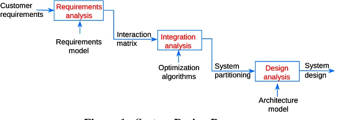
In this section, we present the approach that allows system design engineers to determine low cost EES architectures in multi option product development environments using modular design concepts. The overall design approach is shown in Figure 1 (Zakarian and Rushton 2001).
Customer requirements
Interaction matrix
System partitioning
System design Requirements
model
Optimization algorithms
Architecture model Customer
requirements
Interaction matrix
System partitioning
System design Requirements
model
Optimization algorithms
[image:2.612.135.485.532.656.2]Architecture model
Figure 1 - System Design Process
Requirements analysis
Integration analysis
Design analysis Requirements
analysis
Integration analysis
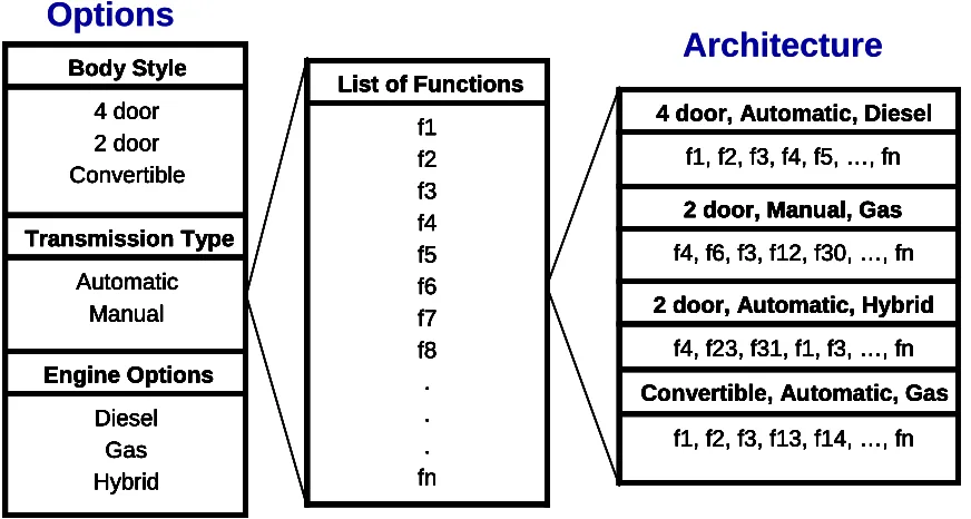
System modeling is used to develop a functional requirements model for a system. The system requirements model defines the interfaces (interactions) between system functional elements (primitives) to support functions of various product configurations. From this functional requirements model, the system design engineer may capture the requirements of multiple product configurations (see Figures 2 and 3). For example, three different configurations could be as follows: 1) four-door body style, automatic transmission, and diesel engine; 2) two-door body style, automatic transmission and hybrid engine and 3) convertible body style, automatic transmission and gas engine. It is clear that some of the functions of the EES architectures that support the above configurations are mutually exclusive. For example, the EES architecture that supports a two-door body style configuration may not have some of the functions that are required for the EES architectures that support a four door or convertible body style configuration. Once the requirements of various vehicle configurations are captured and the interfaces among the functional elements that support all these different configurations are identified, a function-function interaction (incidence) matrix of the interfaces is developed (see Figure 4). Each row (column) in the interaction matrix corresponds to a function (primitive process or PSPEC), and each non-zero entry in the matrix represents an interaction (data flow) between the functions (PSPEC's). Clustering techniques and optimization algorithms can then be used to identify a low cost EES architecture that supports all three vehicle configurations. The objective of the clustering algorithm is to determine an optimal (low cost) common EES system architecture for given features and feature take rates by grouping (integrating) system functions into physical modules and determining the best possible tradeoffs between system overhead, give away, and wiring costs.
Diesel Gas Hybrid Engine Options Automatic Manual Transmission Type 4 door 2 door Convertible Body Style Diesel Gas Hybrid Engine Options Automatic Manual Transmission Type 4 door 2 door Convertible Body Style f1 f2 f3 f4 f5 f6 f7 f8 . . . fn
List of Functions
f1 f2 f3 f4 f5 f6 f7 f8 . . . fn
List of Functions
f1, f2, f3, f13, f14, …, fn Convertible, Automatic, Gas
f4, f23, f31, f1, f3, …, fn 2 door, Automatic, Hybrid
f4, f6, f3, f12, f30, …, fn 2 door, Manual, Gas f1, f2, f3, f4, f5, …, fn 4 door, Automatic, Diesel
f1, f2, f3, f13, f14, …, fn Convertible, Automatic, Gas
f4, f23, f31, f1, f3, …, fn 2 door, Automatic, Hybrid
f4, f6, f3, f12, f30, …, fn 2 door, Manual, Gas f1, f2, f3, f4, f5, …, fn 4 door, Automatic, Diesel
Options
Architecture
Diesel Gas Hybrid Engine Options Automatic Manual Transmission Type 4 door 2 door Convertible Body Style Diesel Gas Hybrid Engine Options Automatic Manual Transmission Type 4 door 2 door Convertible Body Style f1 f2 f3 f4 f5 f6 f7 f8 . . . fnList of Functions
f1 f2 f3 f4 f5 f6 f7 f8 . . . fn
List of Functions
f1, f2, f3, f13, f14, …, fn Convertible, Automatic, Gas
f4, f23, f31, f1, f3, …, fn 2 door, Automatic, Hybrid
f4, f6, f3, f12, f30, …, fn 2 door, Manual, Gas f1, f2, f3, f4, f5, …, fn 4 door, Automatic, Diesel
f1, f2, f3, f13, f14, …, fn Convertible, Automatic, Gas
f4, f23, f31, f1, f3, …, fn 2 door, Automatic, Hybrid
f4, f6, f3, f12, f30, …, fn 2 door, Manual, Gas f1, f2, f3, f4, f5, …, fn 4 door, Automatic, Diesel
Diesel Gas Hybrid Engine Options Automatic Manual Transmission Type 4 door 2 door Convertible Body Style Diesel Gas Hybrid Engine Options Automatic Manual Transmission Type 4 door 2 door Convertible Body Style f1 f2 f3 f4 f5 f6 f7 f8 . . . fn
List of Functions
f1 f2 f3 f4 f5 f6 f7 f8 . . . fn
List of Functions
f1, f2, f3, f13, f14, …, fn Convertible, Automatic, Gas
f4, f23, f31, f1, f3, …, fn 2 door, Automatic, Hybrid
f4, f6, f3, f12, f30, …, fn 2 door, Manual, Gas f1, f2, f3, f4, f5, …, fn 4 door, Automatic, Diesel
f1, f2, f3, f13, f14, …, fn Convertible, Automatic, Gas
f4, f23, f31, f1, f3, …, fn 2 door, Automatic, Hybrid
f4, f6, f3, f12, f30, …, fn 2 door, Manual, Gas f1, f2, f3, f4, f5, …, fn 4 door, Automatic, Diesel
Options
[image:3.612.89.525.397.630.2]Architecture
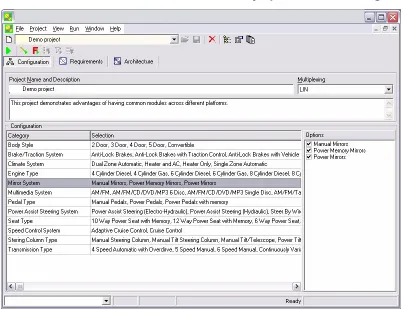
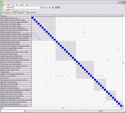
Figure 3 - SA builder Software Interface for Selecting Various Vehicle Configurations SA builder software presented in this paper allows the system design experts to import the requirements model into a database; and select constraints for the various vehicle configurations (see Figure 3). Once the requirements for each vehicle configuration are identified the SA builder software tool automatically builds a function – function interaction matrix (see Figure 4). A function - function interaction matrix [aij] is shown in Figure 4 and includes integer, as well as “blank” entries, where an integer entry indicates the information, material or energy link (data flow) between functions i and j, and the direction of the link (flow) is from j to i. The integer also indicates the number of signals or flows sent from function j to function i. One may see that the matrix in Figure 4 is not binary but weighted.
Figure 4 - Function – Function Interaction Matrix
Figure 5 - Common EES Architecture Matrix
Next, we present a review on different clustering techniques and briefly explain the approach of the optimization algorithms used in the SA Builder software tool.
Cluster Analysis Techniques
Traditional clustering algorithms can be classified into two main categories: hierarchical and partitional methods. Partitional methods create a unique partition of objects or data sets while hierarchical methods produce several nested partitions of objects.
Hierarchical clustering techniques construct tree structures reflecting the underlying patterns in a given data set. The trees obtained by this clustering method are called dendograms and are typically binary. A dendogram consists of several layers of nodes representing different clusters and are typically used to highlight the similarity between clusters. From the dendogram data analysis, different partitions can be built by cutting the tree horizontally using similarity values. The two most commonly used hierarchical clustering approaches are single link and complete link methods (Jain and Dubes 1988, Sneath and Sokal 1973).
Partitional methods create a single partition of points. Approaches in partitional clustering include error square clustering (Cheng and Tong 1991), clustering based graph theory (Tarjan 1972), and density estimation clustering. Error square clustering methods minimize the square error for a fixed number of clusters. Graph based clustering methods examine graph structure, for example using spanning tree method, to identify and remove inconsistent edges of the graph and determine strongly connected components.
Several algorithms and mathematical models have been developed for clustering binary matrices. Most of the mathematical models, i.e., p–median, generalized p–median (Kusiak 2000), require calculations of similarity distances between columns (rows) of the interaction matrix. Other algorithms, i.e., similarity coefficient method (McAuley 1972), rank order clustering algorithms (King 1980), and cluster identification algorithms (Kusiak and Chow 1987) use matrix row and column swapping techniques to obtain clusters in the binary matrix.
Incidence matrices of vehicle system models are large in size (greater than 1,000 rows/columns) and may have binary and non-binary structures. Most of the clustering techniques developed in the literature are primarily designed for clustering binary matrices. Furthermore, algorithms presented in the literature are designed for decomposing binary matrices into mutually separable clusters. System level interaction matrices are large and practically impossible to decompose into mutually separable clusters. In other words, for large matrices, like the ones developed in this research, bottleneck elements (functions) will always exist. An element (entry xij = integer number) is considered a bottleneck, when it does not allow the decomposition of the function – function interaction matrix into mutually separable clusters.
The SA Builder software presented in this paper uses a new clustering algorithm and cost optimization techniques for development of low cost, modular architectures that can be shared across various product platforms. The algorithms can be used for clustering both binary and non-binary (weighted) matrices. The clustering algorithm identifies clusters in the n × n
incidence matrix. For the function - function incidence matrix, the algorithm first creates n
EES Architecture Development Around Common Modules
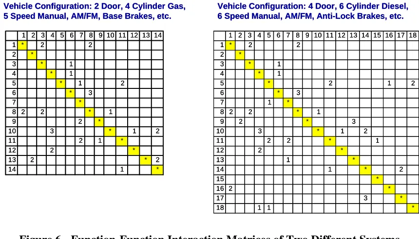
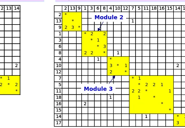
In this section we present an approach that allows system design engineers to identify common modules between EES architectures that support various vehicle platforms (configurations). These common modules are then used in developing optimal low cost EES architectures for each product platform (configuration). Using a system design process similar to that shown in Figure 1, one may develop a requirements model for various vehicle configurations and construct a function – function interaction matrix for each configuration (refer to Figure 4). Once the interaction matrices for the various vehicle configurations are constructed, clustering and graph based techniques may be used to identify common modules (chunks) in the incidence matrices. For example, Figure 6 represents the Interaction matrices of two different requirements models with 14 and 18 functions, respectively. Using clustering and graph based optimization techniques, one may find two clusters that are identical (common) in both incidence matrices (i.e., EES architectures). As shown in Figure 7 clusters (modules) 2 and 3 are in both matrices and have the same structure. Once common modules are identified, one can further cluster matrices in Figure 7 to obtain a final EES architecture (see Figure 8). One may see that in both clustered matrices in Figure 8, the structure of modules 2 and 3 are identical.
1 2 3 4 5 6 7 8 9 10 11 12 13 14 1 2 3 4 5 6 7 8 9 10 11 12 13 14 15 16 17 18
1 * 2 2 1 * 2 2
2 * 2 *
3 * 1 3 * 1
4 * 1 4 * 1
5 * 1 2 5 * 2 1
6 * 3 6 * 3
7 * 7 1 *
8 2 2 * 1 8 2 2 * 1
9 2 * 9 2 * 3
10 3 * 1 2 10 3 * 1 2
11 2 1 * 11 2 2 * 1
12 2 * 12 2 *
13 2 * 2 13 1 *
14 1 * 14 1 * 2
15 *
16 2 *
17 3 *
18 1 1 *
Vehicle Configuration: 2 Door, 4 Cylinder Gas, 5 Speed Manual, AM/FM, Base Brakes, etc.
Vehicle Configuration: 4 Door, 6 Cylinder Diesel, 6 Speed Manual, AM/FM, Anti-Lock Brakes, etc.
[image:8.612.91.521.329.575.2]2 2
2 5 7 9 1 3 6 8 4 10 12 11 13 14 2 5 7 9 1 3 6 8 4 10 12 11 13 14 15 16 17 18
2 * 1 2 *
5 * 1 2 5 * 2 1 2
7 * 7 1 *
9 3 2 * 9 2 * 3
1 * 2 2 1 * 2 2
3 * 1 3 * 1
6 * 3 6 * 3
8 2 2 * 1 8 2 2 * 1
4 1 * 4 1 *
10 3 * 1 2 10 3 * 1 2
12 2 * 12 2 *
11 2 1 * 11 2 2 * 1
13 2 * 2 13 1 *
14 1 * 14 1 * 2
15 *
16 2 *
17 3 *
18 1 1 *
Module 2
Module 3
Module 2
Module 3 Vehicle Configuration: 2 Door, 4 Cylinder Gas,
5 Speed Manual, AM/FM, Base Brakes, etc.
Vehicle Configuration: 4 Door, 6 Cylinder Diesel, 6 Speed Manual, AM/FM, Anti-Lock Brakes, etc.
2 5 7 9 1 3 6 8 4 10 12 11 13 14 2 5 7 9 1 3 6 8 4 10 12 11 13 14 15 16 17 18
2 * 1 2 *
5 * 1 2 5 * 2 1 2
7 * 7 1 *
9 3 2 * 9 2 * 3
1 * 2 2 1 * 2 2
3 * 1 3 * 1
6 * 3 6 * 3
8 2 2 * 1 8 2 2 * 1
4 1 * 4 1 *
10 3 * 1 2 10 3 * 1 2
12 2 * 12 2 *
11 2 1 * 11 2 2 * 1
13 2 * 2 13 1 *
14 1 * 14 1 * 2
15 *
16 2 *
17 3 *
18 1 1 *
Module 2
Module 3
Module 2
Module 3 Vehicle Configuration: 2 Door, 4 Cylinder Gas,
5 Speed Manual, AM/FM, Base Brakes, etc.
[image:9.612.228.511.74.295.2]Vehicle Configuration: 4 Door, 6 Cylinder Diesel, 6 Speed Manual, AM/FM, Anti-Lock Brakes, etc.
Figure 7 - EES Architecture Matrices with Two Common Modules
5 11 9 1 3 6 8 4 10 12 2 13 14 2 13 9 1 3 6 8 4 10 12 7 5 11 18 16 15 14 17
5 * 2 2 *
11 * 1 13 * 1
9 3 * 9 2 3 *
1 * 2 2 1 * 2 2
3 * 1 3 * 1
6 * 3 6 * 3
8 2 2 * 1 8 2 2 * 1
4 1 * 4 1 *
10 3 * 1 2 10 3 * 1 2
12 2 * 12 2 *
2 * 1 7 * 1
13 2 * 2 5 * 2 2 1
14 1 * 11 2 2 * 1
18 1 1 *
16 2 *
15 *
14 1 * 2
17 3 *
Module 2
Module 3 Module 3
Module 2 Vehicle Configuration: 2 Door, 4 Cylinder Gas,
5 Speed Manual, AM/FM, Base Brakes, etc.
Vehicle Configuration: 4 Door, 6 Cylinder Diesel, 6 Speed Manual, AM/FM, Anti-Lock Brakes, etc.
Figure 8 - Clustered EES Architecture Matrices with Two Common Modules
CONCLUSION
[image:9.612.199.496.359.565.2]were presented that allow EES system design engineers to develop modular architectures/modules that can be shared across vehicle platforms (for OEMs) and across OEMs (for suppliers). Approaches presented in this paper used matrix clustering and graph based techniques. The application of the approach was illustrated with an example from the automotive industry
REFERENCES
Birnbaum, P. H., (1977), “Assessment of Alternative Measurements Forms in Academic Interdisciplinary Research Projects”, Management Science, Vol. 24, pp. 272-284.
Cheng, H. D. and Tong, C. (1991), “Clustering Analyzer”, IEEE Transactions on Circuits and
Systems, Vol. 38, No. 1, pp. 124 - 128.
Jain, A. K. and Dubes, R. C., “Algorithms for Clustering Data”, Englewood Cliffs, New Jersey, Prentice Hall, 1988.
King, J. R. (1980), “Machine-Component Group Formation in Production Flow Analysis: An Approach Using a Rank Order Clustering Algorithm”, International Journal of Production
Research, vol. 18, no. 2, pp. 213-232.
Kusiak, A. (2000), “Computational Intelligent in Design and Manufacturing”, Wiley, New York, NY.
Kusiak, A. and Chow, W. S. (1987), “Efficient Solving of the Group Technology Problem”,
Journal of Manufacturing Systems, vol. 6, no. 2, pp. 117-124.
Kusiak, A. and Chow, W. (1988), “Decomposition of Manufacturing Systems,” IEEE Journal of
Robotics and Automation, Vol. 4, No. 5, pp. 457-471.
Kusiak, A. and Huang, C. C. (1996), “Development of Modular Products”, IEEE Transactions
on Components, Packaging, and Manufacturing Technology – Part A, vol. 19, no. 4, pp.
523-538.
Kusiak, A. and Huang, C. C. (1998), “Modularity in Design of Products and Systems”, IEEE
Transactions on Systems, Man, and Cybernetics-Part A: Systems and Humans, vol. 28, no. 1,
pp. 66-77.
Mahajan, V. and Jain, A. K. (1978), “An Approach to Normative Segmentation”, Journal of
Market Research, Vol. 15, 338-345.
McAuley, J. (1972), “Machine Grouping for Efficient Production”, The Production Engineer, February, pp. 53-57.
Ng, S. M. (1991), “Bond Energy, Rectilinear Distance and Worse-case Bound for the Group Technology Problem,” J. of Operations Research, Vol. 42, No. 7, pp. 571-578.
Ni, L. M. and Jain, A. K. (1985), “A VLSI Systolic Architecture for Pattern Clustering”. IEEE
Transactions on Pattern Analysis and Machine Intelligence, Vol. 7, pp. 80-89.
O'Grady, P. (1999), “The Age of Modularity: Using the New World of Modular Products to Revolutionize Your Corporation”, Wiley, New York, NY.
Pimmler, T. U. and Eppinger, S. D. (1994), “Integration Analysis of Product Decomposition”,
Design Theory and Methodology – DTM, DE-vol. 68, ASME.
Sneat, P. H. and Sokal, R. R., “Numerical Taxonomy. San Francisco”, CA. W. H. Freeman, 1973.
Tambouratzis, G. (2002), “Improving the Clustering Performance of the Scanning n-Tuple Method by Using Self Supervised Algorithms to Introduce Subclasses,” IEEE Transactions
on Pattern Analysis and Machine Intelligence, Vol. 24, No. 6, pp. 722-733.
Tarjan, R. (1972), “Depth-First Search and Linear Graph Algorithms”, SIAM Journal of
Computing, vol. 1, no. 2, pp. 146-160.
Ulrich, K. and Tung, K. (1991), “Fundamentals of Product Modularity”, DE-vol. 39, Issues in
Design Manufacture/Integration, ASME.
CONTACT
Gary Rushton has over 18 years of commercial and military electrical/electronic systems engineering experience. He has an MS in Automotive Systems Engineering from the University of Michigan. He is currently working as an electrical/electronic/software systems engineer specialist with Visteon Corporation. As an engineer with Visteon Corporation, he has worked on audio software, subsystem product development/design, diagnostics, vehicle system architectures, and cockpit system design. Previously, with General Dynamics, he worked on avionics systems for the F-16 and vetronics systems for the Abrams M1A2 tank. He has published several papers in journals sponsored by IEEE, INCOSE, and SAE. He also holds several patents. ([email protected]).
Armen Zakarian received his B.S. degree in mechanical engineering from Yerevan Polytechnic University, Yerevan, Armenia, his M.S. degree in industrial and systems engineering from the University of Southern California, Los Angeles, California and his Ph.D. degree in industrial engineering from the University of Iowa, Iowa City, Iowa, in 1997. He is an Assistant Professor of Industrial and Manufacturing Systems Engineering at the University of Michigan - Dearborn. His research interests are in development of integrated products and system, process modeling and analysis and manufacturing system. He has published papers in journals sponsored by ASME, IEEE and IIE societies. ([email protected]).