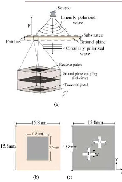
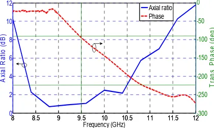
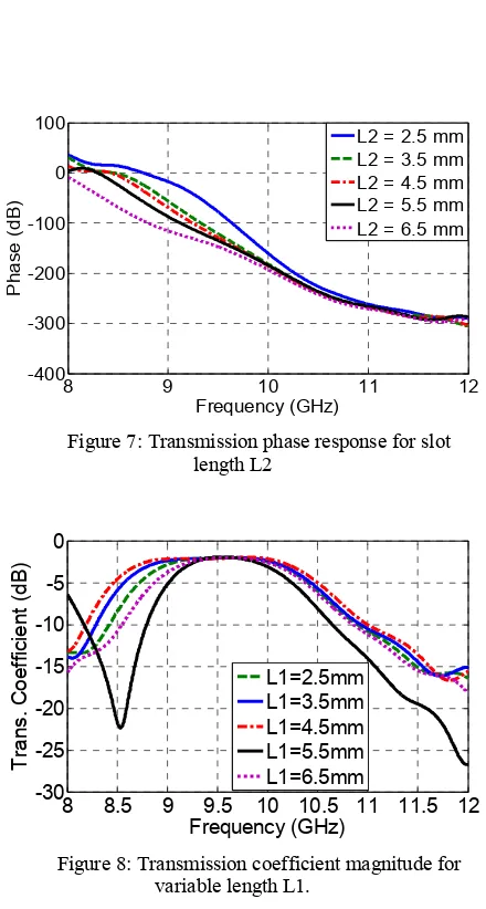
A circularly polarized aperture coupled patch element for flat lens antennas
Full text
Figure
Related documents
Starting from the left edge of the game screen search for the first point with color value equal to that of the strip (yellow with some allowed variance). This point marks
Furthermore, we induce two types of constrained policies: CAPOMDP LG using learning gain as the immediate reward for improving students’ learning performance, and CAPOMDP Time us-
Since genes which modify or suppress the effect of A” on color show no corresponding effect on its lethal action or its tendency to produce adi- posity, and those
The scope of this exercise is to furnish opinion on the following: a) Setbacks to be left from the Raja Kaluve ( Nala ). b) Regular set back based on the balance land area
The silence region is characterized by the absence of any signal characteristics, lowest energy compared to unvoiced and voiced speech segments, relatively more number
The binding energy shifts in the SXPS Al 2 p and Ta 4 f core levels and AES 共 Al–O 兲 and 共 Ta–O 兲 peaks with alloy composition have been attributed to the combination
Figure 5.12 Multicyclic four-point bending test of composite coupon: (a) & (b) Normalized resistance change & strain increase VS number of cycles for six CNT sheets
The proposed framework is compared with other learning-based equalization schemes, namely C-ELM, CRBF, CMRAN, k-nearest neighbor (k-NN) [88], back propagation (BP) neural
