Design and Implementation of an Embedded Ball-beam
Controller Using PID Algorithm
Mustafa Saad
*, Mohammad Khalallah
Department of Control Engineering, College of Electronic Technology, Bani-walid, Libya
Copyright©2017 by authors, all rights reserved. Authors agree that this article remains permanently open access under the terms of the Creative Commons Attribution License 4.0 International License
Abstract
Ball and beam system is found in most laboratories of control systems engineering due to its simplicity and easiness in construction and control theoretically. The system consists of a motor attached with a beam at the center and a ball, which is placed on the top of beam. The problem with this system, is in the time of an electrical control signal is applied to the motor, the beam can be tilted about its horizontal axis and the ball will roll on the top of the beam. Therefore, if the system cannot be controlled properly, the ball may fall down from the beam. In this paper, PID controller Algorithm based on Arduino microcontroller which depends on the feedback signal is used to control the ball position using linear potentiometer position sensor. MATLAB software program has been used to plot the system response by observing the ball position for a predefined amount of time. The controller parameters have been tuned using trial and error method, tested for different set point tracking and for disturbance rejection in order to obtain a good system characteristic.Keywords
Ball and Beam System, Hardware Model, Embedded PID, Arduino1. Introduction
The control of unstable systems is an important task in control engineering. Since these systems are considered to be dangerous if they were unstable, these systems can only be studied in laboratories. The ball and beam system which is also called "ball on beam balancer" is basically related to a real system problem such as horizontal stability of an airplane during landing or in turbulent air flow. The fundamental application of this system can be seen in many industrial applications such as precise position control in assembly lines in some factories such as water purification factories. The ball and beam system is very easy to understand, and many control techniques can be studied on this system to cover many classical control design methods.
This system is common feedback control system, due mostly to its simplicity in construction, and its use in learning for applying control to stabilize an unstable system. This system is unstable and needs to be stabilized. There are many features of using ball and beam system. One of these features is that it shows how the controller works and how it reacts to disturbance. Another feature is that it is inexpensive and mechanically simple for construction.
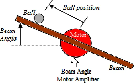
[image:1.595.305.541.488.633.2]The ball and beam system can be categorized into two configurations. The first configuration is shown in Figure 1, in this type the beam is supported in the middle, and it rotates against its central axis. Most ball and beam systems use this type of configuration. This type of configuration is normally called as ‘Ball and Beam Balancer’. This type has the advantage of easiness of building and the simplicity of the mathematical model.
Figure 1. Beam supported at the center
that relatively small motor can be used due to the existing of gear box [1].
Figure 2. Beam supported at both side
There are many of control strategies and methods in controlling the position of ball in the ball-beam system such as a robotic ball balancing beam [2], ball and beam balancer control using microcontroller [3] application of a LabVIEW for real-time control of ball and beam system [4], Design and implementation of ball and beam system using PID controller [5], Design and Implementation a Ball Balancing System for Control Theory Course [6].
2. Model Implementation
There are many conditions have to be considered when the designing of ball and beam balancer model has to be started, such as length of the beam, weight, material and size of the ball that will be used. Also, a good choice for the components is essential to make sure that the system works properly. So, the system model can be categorized into two parts; the mechanical part and the electrical part.
2.1.The Mechanical Part of the System
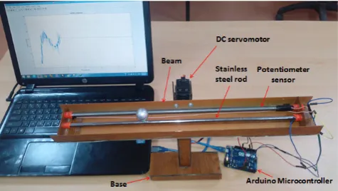
The beam is made from an aluminum, and has a rectangular shape with a length of 35 cm, width of 5 cm, and depth of 2 cm to make the body of the beam and the path of the ball. Aluminum was chosen due to its lightness. For the ball and beam system, a base is needed for the system to be stable, holding the actuator, and also for preventing the model from vibrating. The base is made of iron steel, due to its rigid, and heavy material. The upper part of the base is designed appropriately to hold the actuator.
2.2.The Electrical Part of the System
The electrical part consists of Linear potentiometer. DC servo motor. Arduino Leonardo.
A resistive wire potentiometer is chosen in this paper as a position sensor which has a good distance detection. Resistive wire position sensor is a rod with 31 cm long that is coiled with a resistive wire. One end of the wire is connected with a source of 5 Volt, and the other is connected to the ground. This rod associated with another stainless steel rod to make rail for the ball to roll on it. A metal ball is needed to conduct between the resistive wire rod and the stainless steel rod. The stainless steel rod will be connected to the microcontroller to give the position of the ball depending on its position on the sensor.
Servo motors are DC motors equipped with a servo mechanism for precise control of angular position. Where, the servo motors usually have a rotation limit from 0° to 180° and it require only PWM signal to start working. The PWM signal depends on the sensor reading from the resistive position sensor. When the sensor detects the position of the ball, the microcontroller will send a PWM signal to the servomotor which in turn will rotate to a certain angle to make the ball move.
Arduino Leonardo microcontroller is an electronic board that contains Atmega328 microcontroller, designed for electronic control applications. Arduino can be programmed by using Arduino C. This board is used in this research due to its inexpensive hardware, simple programming environment for beginners and yet flexible enough for advanced users
With regard to the ball, a metal ball is used for the purpose of conducting between the resistive wire position sensor and the stainless steel rod.
Since the mechanical part has been designed and an appropriate components have been selected The prototype model of the system is shown in Figure 3.
[image:2.595.304.542.485.619.2]Figure 4. Ball and beam system circuit connection
3. PID Controller Design
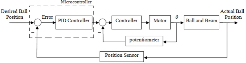
The PID controller is a well-known industrial feedback control algorithm, which can be designed by non-model based methods [7]. Figure 5 shows the block diagram of this approach for controlling the ball and beam system. In this system an embedded PID controller algorithm has to be designed to control the ball position which is the outer loop of the block diagram by processing the error difference between the desired and actual ball position. While the inner loop is the loop for the DC servo motor, which include its own controller to control the motor angle by processing the error between the desired angle and the motor angle which measured by rotary potentiometer. Since the motor is attached with the beam, the beam angle can be controlled by controlling the motor angle. The ball and beam subsystem, independent to the motor, is an unstable system; therefore, the PID control gains should control and stabilize the system.
Figure 5. Block diagram of the ball and beam PID control system
The mathematical equation of the PID controller may be expressed in various ways, but a general formula is:
PIDoutput = Kp∗Error + Ki∗ ∫0tError+ KddErrordt (1) where Kp, Ki, and Kd, all non-negative, denote the coefficients for the proportional, integral, and derivative terms, respectively.
The proportional term deals with present values of the error. For example, if the error is large and positive, the control output will be proportionately large and positive. Proportional control alone will always have an error between the set point and the actual value, because it requires the error to generate the proportional response; so if there is no error, there is no response.
[image:3.595.84.509.449.559.2]The derivative term accounts for possible future trends of the error, based on its current rate of change. It is sometimes called "anticipatory control" as it is effectively seeking to reduce the effect of the error by exerting a control influence generated by the rate of error change. The more rapid the change, the greater the controlling or dampening effect.
Equation (1) which is continuous time PID controller can be approximated to the equivalent discrete time PID controller. Where, the Integral term is approximated into the sum of two values of error, the present error, and the previous error. Also, the derivative term is reformulated into the difference between the mentioned errors.
PIDOutput= Kp∗Error + Ki∗(Error + Previos Error) + Kd∗(Error−Previos Error) (2)
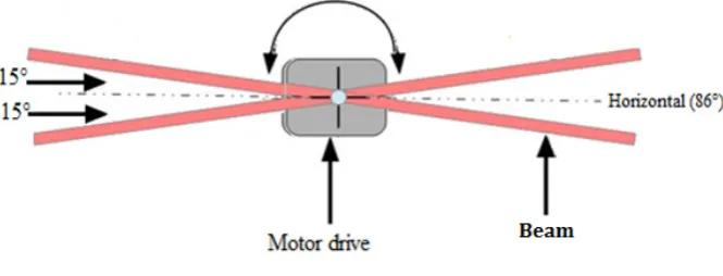
[image:4.595.133.466.308.435.2]PID controller is designed for this ball and beam balancer system due to the instability of the system as an open loop system. There are various tuning methods that can be used to tune the PID controller parameters Kp, Ki, and Kd. In this paper, the tuning method that has been used is the "Trail and error" method. The values are chosen due to some mathematical calculations, which depend on the programming of the PID controller. To do these calculation, two things in the programming must be known. First thing is that the maximum tilting degree of the beam is ±15°. This means that the beam will tilt by a maximum of 15° to the left or to the right. The second thing is that the servomotor input equals the sum of the motor angle, that will make the beam horizontal with the output of the PID. In this project the horizontal angle of the beam is set to 86°, as well as, the error equals to zero, the servomotor will always be fixed at 86°.Which indicates that, the PID output equal to zero. Figure 6 shows the beam rotating limits.
Figure 6. Beam rotation limits
To choose the controller parameters Kp, Ki and Kd values, assume that the error increased from 5 cm to 6 cm. This means that, the present error equals to 6 cm, and the previous error equals to 5 cm. Also assume that PID_Output equals to 15°. By substituting these value in equation (2).
PID_Output = Kp∗6 + Ki∗(6 + 5) + Kd∗(6−5) = 15 Let Ki to be 0.2, and for simplicity, let Kp= Kd= K.
Hence;
K = 1.8
According to the previous calculations, the values of Kp= 1.8, Ki= 0.2, and Kd= 1.8 are used as starting point for the PID controller tuning.
4. Test the Designed System and
Modification
The designed system is tested to ensure that the controller can stabilize the ball position at any desired position. If it is not, repeat the process until success is exceeded by modification of the program.
During the test of the ball and beam system, there have been many problems which need to be solved. The first one is that the servomotor angle was very large. The solution is using gears to reduce the angle, but the problem is that the servomotor is a solid state device. Due to this, a modification has been done in the program code
to adjust the beam angle instead of adjusting the gear of the motor as shown in equation (3).
ServoOutput = horizontal angle + (PID_Output/3) (3) Where horizontal angle is an offset angle that makes the beam horizontal, which the microcontroller servomotor library will automatically turn the desired angle value into the needed voltage for the servomotor to reach that angle. The factor (1/3) has no unit, this means that it does not effect on the unit of the PID_Output, which is an angle, thus, the equation is balanced.
the beam is very small. When the beam is tilted from the horizontal position to put the ball at desired position, the velocity of the ball is too high, which means there is no friction between the ball and resistive wire to stop the ball from rolling. As a result, the system could not stabilize the ball at the desired position. Figure 7 shows the first attempt to stabilize the ball at the desired position of 14 cm.
Figure 7. Ball position response without covering the ball with aluminum
From Figure 7, it can be seen that the system cannot be stabilized at the desired set point. Even though, the controller parameters have been tuned using trial and error method. The system tried to stabilize the ball at the desired position between the time of 10 s. and 13 s. But due to the smoothness of the ball, the ball kept rolling all the time. To overcome this problem, the applied solution is to increase the friction between the ball and the beam by enveloping the ball with aluminum foil.
5. Real Time System Results
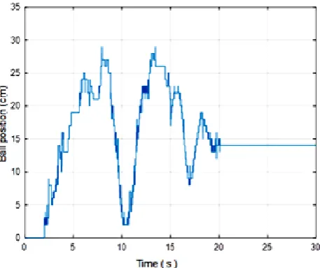
[image:5.595.309.540.80.269.2]This section demonstrates the results of a real time plotting of ball and beam balancer system, by using the PID controller with trial and error method. MATLAB software is used to plot the output response of the system. The desired value of ball position on the beam is set to be 14 cm, this set point can be changed at any desired position by changing it in the program. By substituting the values of the controller parameters with Kp= 1.8, Ki= 0.2, and Kd= 1.8. Figure 8 shows the output response of the ball position. It's clear that the system oscillates about the set point, which is 14 cm. In this case, the system is considered to be marginally stable. Therefore, these values of the controller parameters can't stabilize the ball at the desired position. Due to this problem, a tuning to the PID controller parameters is needed.
Figure 8. Ball position response with Kp=1.8, Ki=0.2, Kd=1.8
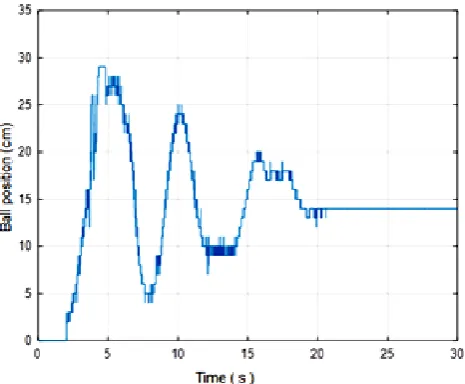
[image:5.595.59.293.185.379.2]During trial and error, it has been noticed that the most effective controller parameter on the system stability is the integral term. Therefore, the integral term is set to zero (Ki= 0) to make the system stable, with the same values of Kp and Kd. Figure 9 shows the real time plotting of ball position with Kp= 1.8, Ki = 0 and Kd= 1.8 Exterminating the integral term helped in stabilizing the system with zero steady state error. However, the transient response has a high overshoot, almost 100%, with high oscillation, and the settling time is approximately 18 s. In order to improve the overshoot and the settling time, the controller parameters Kp and Kd have to be decreased.
Figure 9. Ball position response with Kp=1.8, Ki=0, Kd=1.8
[image:5.595.309.538.451.643.2]overshoot is still a problem, since it is almost 100%overshoot. The proportional term still has to be decreased to reduce the overshoot. In contrast, the derivative term has to be increased to improve the transient response.
Figure 10. Ball position response with Kp=1, Ki=0, Kd=0.75
Figure 11 shows the output response of the ball position with the new values of Kp= 0.85, Ki= 0, and Kd= 1.1. These changes caused the system to be much better in terms of overshoot, which is reduced by 50% approximately, and the settling time, which is approximately 8 s.
Figure 11. Ball position response withKp=0.85,Ki=0, Kd=1.1
To test the system accuracy, the set point has been changed to 10 cm and 20 cm, as shown in Figure 12 and Figure 13 respectively with same values of the controller parameters Kp= 0.85, Ki= 0, and Kd= 1.1.
Figure 12. Ball position response for set point 10 cm
Figure 13. Ball position response for set point 20 cm
For both cases, the steady state error is zero, the overshoot is very nearly to 50%. The difference is that for the settling time. For set point of 10 cm settling time is approximately 5.5 s. while for set point of 20 cm settling time is approximately 8 s.
[image:6.595.307.540.79.271.2] [image:6.595.60.293.142.334.2] [image:6.595.307.540.301.500.2] [image:6.595.61.293.436.629.2]Figure 14. Block diagram of ball and beam balancer under effect of disturbance
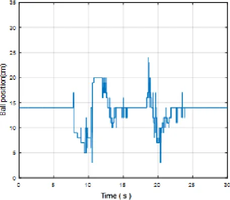
To show the ability of the controller for the disturbance rejection that acting on the system, a force has been applied on the ball, to roll it from its desired position and see whether the controlled system can return the ball to its desired position or not. When the ball at the desired position (14 cm) on the beam, there were two forces have been applied on the ball at different times as an external disturbance. The real time plot of ball position under effecting of these forces is shown in Figure 15.
Figure 15. Real time plot for the system under effect of disturbance From the real time plot of the system under effect of disturbance, it can be seen that, the system was under effect of disturbance at two different times. The first time between (8 s. and 14 s.) and the second time of the disturbance effecting between (18 s. and 24 s.). The controller has the ability to stabilize the system again and return the ball to its desired position in few of seconds. Hence, the disturbance has been rejected.
6. Conclusions
This paper has four objectives achieved which are, a real
time model of ball and beam system has been developed and completely designed, PID controller algorithm of the hardware system using Arduino C language has been designed, the output response of the ball position using MATLAB software has been obtained and finally, the controller parameters had been tuned from the experimental results.
Regarding the ball, it should be chosen properly. Firstly, the mass of the ball must be light enough to move the motor, and heavy enough to make appropriate weight on the position sensor to give a good reading. Secondly, ball friction is small to allow the ball rolling, and large for stopping the ball while the beam in horizontal position.
The main contributions of this project are the algorithm that has been used as starting up for the PID controller parameters. Another contribution, was adjusting the beam angle which is the output of the servo motor in the program code as proposed in equation (3), instead of adjusting the gearbox of the servo motor.
By using trial and error tuning method and with the help of proposed equation (2) the best values of the PID controller parameters are Kp=0.85, Ki=0, and Kd=1.1 that gave the best response in terms of both transient response and steady state response.
For the PID parameters, the integral term caused the system to be oscillated; due to the mechanism of the integral term in the PID controller, which is adding error to the previous error. This means that when the ball reaches the desired position, the motor angle is not in the horizontal position, which will cause the ball to roll away from the set point. Therefore, the integral term was canceled and the proposed controller became two terms PD controller rather than three terms PID controller. In addition, the force that accelerates the ball as it rolls on the beam comes from the component of the gravity that acts parallel to the beam. As a result, there is no need for integral term for step and ramp input due to the dynamic of the model.
[image:7.595.119.482.84.233.2] [image:7.595.64.293.376.575.2]accuracy for the set point tracking.
The performance of the system controlled is considered in presence of an external disturbance and the results illustrated that the proposed PD controller performed satisfactorily in the rejection of disturbance. Hence, it can be conclude that the robustness of the proposed controller is investigated.
REFERENCES
[1] M. F. Rahmat, H. Wahid, and N. A. Wahab, “Application of intelligent controller in a ball and beam control system,” International journal on smart sensing and intelligent systems, vol. 3, pp. 45-60, 2010.
[2] Jeff Lieberman, “A robotic ball balancing beam," B.Sc. Physics, Massachusetts Institute of Technology, 2004.
[3] Nadiah Binti Ismail, “Ball and beam balancer control using microcontroller,” M. Sc. Thesis, UTM, Malaysia, 2009. [4] Basil Hamed, “Application of a LabVIEW for Real-Time
Control of Ball and Beam System,” IACSIT, Vol.2, No.4, pp. 401-407, August 2010.
[5] A. Taifour Ali, Ahmed A. M., Almahdi H. A., Osama A. Taha, A. Naseraldeen A. , “Design and implementation of ball and beam system using pid controller,” Automatic control and information sciences, Vol. 3, No. 1, pp. 1-4, 2017.
[6] Zhen Gao, Sahan Wijesinghe, Thushan Pathinathanpillai, Eric Dyer, Ishwar Singh, “Design and implementation a ball balancing system for control theory course,” IJMEC, Vol. 5(17), pp. 2363-2374, Oct. 2015.