Application of Injector-Volume Ratio Values in the Development of a
Fuel Injection Controller
Mas Fawzi
a*, Norrizal Mustaffa
b, Mohd Faisal Hushim
cand Shahrul Azmir Osman
dAutomotive Research Group, Center for Energy and Industrial Environment Studies, Faculty of Mechanical and Manufacturing Engineering, Universiti Tun Hussein Onn Malaysia, 86400 Parit
Raja, Batu Pahat, Johor, Malaysia.
a[email protected]*, b[email protected], c[email protected], d[email protected]
Keywords: Fuel injection, Signal controller, Injector-volume ratio
Abstract: The primary function of an electronic control unit (ECU) of an engine is to calculate the amount of fuel to be delivered into the combustion chamber. The injection duration and duty cycle of the injector will be based on several sensors whose signals the ECU will process to ensure the best engine running condition. However, to study new injection and combustion strategies, where such operation is unavailable in standard ECU, a custom-built fuel injection control system need to be made. This paper describes the development of a fuel injector signal controller, which is being used for internal combustion engine experiment or for the evaluation of any fuel injector static flow rate. Herewith a new term Injector-Volume Ratio (IVR) was introduced to assist the development process. Using the custom-built fuel injection controller, the static flow rate of an injector for a single cylinder 125cc motorcycle engine was determined in accordance to SAEJ1832. From the experiment, the IVR value is proven useful in choosing the right size of a fuel injector to fit any specified engine displacement of a spark ignition engine.
Introduction
The main function of an electronic control unit (ECU) of an engine is to control the fuel injectors. The injection duration and duty cycle were computed and corrected from several inputs, such as air temperature, throttle position, manifold pressure, lambda sensor and etc. [1,2]. There are also other methods that utilize a pre-programmed lookup table as a source of input as well as for correction factors. In doing research for internal combustion engine, a custom-built fuel injector control system is needed to produce injection duration and duty cycle that correspond to any scenarios of study, such as lean combustion, multi-stage injection and etc. Such type of operation is normally unavailable in standard ECU, but is necessary for research purpose. This paper shall describe the development concept of a fuel injector control system.
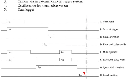
An example of a signal timing diagram is presented in Fig.1. This timing setup is being used by the author in the works related to gas-jet ignition with two-stage injection using a constant volume chamber [3,4]. The signals begin from a user input (A) and ends with a spark ignition (H). The main reference of this setup is the spark ignition timing (H), where in actual engine happens near top dead center (TDC). Since the spark ignition requires capacitive/inductive charging, the igniter coil is fed with a signal (G) a few milliseconds prior to the spark ignition event. The length of the charging should be sufficient to generate enough energy in spark form to initiate a flame kernel for the combustion. Either signal C or D is generated for single injection studies. The end of the injection timings should make allowance for injector needle/pintle magnetic delay and movement delay. For multi injection studies, signal timing E or F was used, where second pulse is optimally set with the spark ignition timing (H) to produce the gas-jet ignition.
Single-shot Controller
input voltage in the input detector. This generated signal duration is relatively long and its purpose is just to generate a 5V square wave to feed the signal processor. It will eliminate most inconsistencies associated with the act of pressing a push button by any user, such as double-push or intermittent-push, allowing for jitter-free trigger signal.
The signal from the input detector is then fed into a signal processor. The signal processor is responsible for creating new signals to meet any output criteria. The signal processing involves three sub operations: setting the output pulse width, setting the output signal delay with respect to the input signal, and producing two signal pulses for multi injection when necessary. All signals leaving the processor are conditioned to ensure the following characteristics: valid TTL signals, and low signal noise. Leaving the conditioner, the signals are sent to the following equipments:
1. Fuel injector via an injector driver 2. Spark igniter via an igniter coil
3. Camera via an external camera trigger system 4. Oscilloscope for signal observation
5. Data logger
t0 A. User input
tst B. Schmitt trigger
ts1 C. Single injection
ts1 D. Extended pulse width
tm1 tm2 E. Multi injection
tm1 tm2 F. Extended pulse width
tg0 G. Igniter coil charging
[image:2.595.82.511.239.506.2]tign H. Spark ignition
Fig.1 Signal timing diagram for gas-jet ignition with two-stage injection
Fig. 2 Single-shot fuel injector controller signal flow diagram
Injector-Volume Ratio
The timing circuit of this fuel injection controller was designed to satisfy an actual spark ignition (SI) engine operating conditions from an equivalence ratio of 0.7 (lean) to 1.2 (rich). For this purpose a chart was made to to provide a guideline in choosing the right size of fuel injector to fit
User input Input detector
Signal processor
Signal output conditioner Pulse width
Delay
No of pulses
Injector driver
Igniter coil
Injector
Spark Igniter
Camera
Osciloscope Camera
trigger
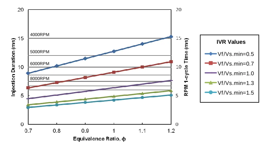
[image:2.595.90.477.544.692.2]any specified engine displacement. Figure 3 shows a chart of injection duration (ms) against equivalence ratio for normal engine operating condition. A new term “Injector-Volume Ratio” (IVR) was introduced and plotted on the graph. The IVR is described as in Equation 1, where Vf is
the injector static flow rate in cc/min and Vs is the engine swept volume in cc.
Injector-volume ratio, IVR = Vf / (Vs.min) (1)
The term IVR itself is independent of the engine speed. However, on the same figure, there are horizontal lines that indicate time of each cycle at engine speeds from 3000 to 8000 RPM. These lines are included in the figure to show that the injection duration should be lower than time available in each cycle at any engine speed. For example, an engine operating with a maximum speed of 8000 RPM should use IVR larger than 1.3, whereas another engine operating at a maximum speed of 5000 RPM may able to use a minimum value of IVR = 1.0.
[image:3.595.88.509.386.615.2]From the given term, IVR of 0.5 represents a low static flow rate injector coupled with a large cylinder displacement volume. On the other hand, IVR value of 1.5 represents a high static flow rate injector coupled with a relatively low cylinder displacement volume. For example, for IVR = 1.0, if a cylinder size is 200 cc, then the fuel injector static flow rate would be 200 cc/min; whereas if a cylinder size is 350 cc, then the injector static flow rate would be 350 cc/min. Besides the use during new engine design stage, the IVR value is also useful when an engine is rebored to a larger displacement, which raises an important question: Is it necessary to change the fuel injector to a higher flow rate? Because there is a significant difference between IVR = 0.5 and 1.5 in terms of the injection duration.
Fig. 3 Injector-Volume Ratio
The IVR values and the plot shown in Fig.3, were used in this work to decide on the range of the injection duration. From the figure, by following this guided values of IVR, the fuel injection signal duration can be limited from 2 to 15 ms. By obtaining this information, appropriate values of R-C timing circuit can be applied to enable those operating signal durations. The values of R-C timing circuits were chosen from the SN74221 Dual Monostable Multivibrators datasheet [5]. In this work, the value of IVR=1.0 was chosen. Such value represents an SI engine operating up to 7000 RPM, which gives an injection duration of less than 10 ms. Thus, taken from the data sheet the appropriate values of Cext would be 1uF, and the Rext should be set by a 20kΩ potentiometer.
0 5 10 15 20
0.7 0.8 0.9 1 1.1 1.2
In
je
c
ti
o
n
D
u
ra
ti
o
n
(
m
s
)
Equivalence Ratio, ɸ
Vf /Vs.min=0.5
Vf /Vs.min=0.7
Vf /Vs.min=1.0
Vf /Vs.min=1.3
Vf /Vs.min=1.5 4000RPM
5000RPM 6000RPM 8000RPM
Fuel Injection Test
[image:4.595.96.495.237.453.2]Next, the completed circuit was assembled and tested in a prototype fuel injector test apparatus. Some modifications were made to the signal fed to the injector so that it was able to perform static flow rate test in accordance with the SAE Standard Practice SAEJ1832 [6]. An image of a test apparatus along with a diagram of the fuel injector flow rate measurement is shown in Fig. 4. For this experiment a fuel injector for 125cc Honda motorcycle was tested. During this test, the fuel injector dynamic flow Qd at a rated pressure for a given pulse width (PW) was measured. From the dynamic flow data, the static flow rate, Qs of the injector was determined. The rated value of the injector static flow rate provides vital information in controlling the amount of fuel injected at a specific engine-operating map by designating a correct PW.
Fig. 4 Fuel injector test apparatus
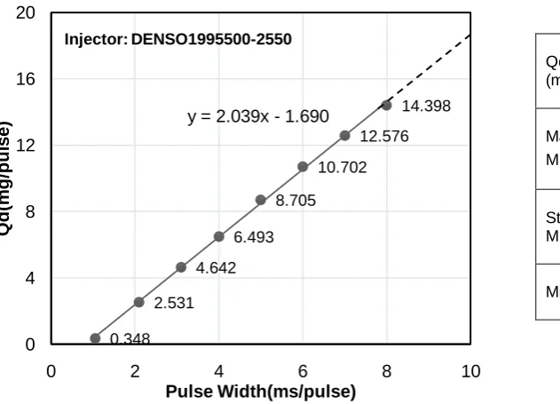
Fig. 5 Injector static flow rate test result
0.348 2.531
4.642 6.493
8.705 10.702
12.576 14.398 y = 2.039x - 1.690
0 4 8 12 16 20
0 2 4 6 8 10
Q
d
(m
g
/p
u
ls
e
)
Pulse Width(ms/pulse)
Injector: DENSO1995500-2550
Qd at 100% IDC
(mg/pulse) 18.7
Mass flow rate at 0.3
MPa, m (g/s) 1.87
Static flow rate at 0.3
MPa, Qs (cc/min) 149.6
Minimum PW (ms) 1.0 Fuel tank
Fuel flow
Pump injector Fuel Pressure regulator Oscillo
scope Fuel injection controller
Fuel Injector
Gasoline tank with submersible electric fuel pump
Fuel Injection Controller box
[image:4.595.70.386.513.740.2]As shown in Fig. 4, the liquid fuel was pressurized by in-tank electric fuel pump and its pressure was regulated at 0.3 MPa. The injector controller was preset with fixed injection period at 10 ms/pulse. The weight of the fuel injected for 1,000 pulses were collected using a beaker and then was measured using an electronic balance. The procedure was repeated for each PW of 1, 2, 3, 4, 5, 6, 7, and 8 ms/pulse. The PW and the injection period signaled to the injector were affirmed using a digital oscilloscope. From the measurements, a graph of fuel dynamic flow, Qd (mg/pulse) versus injector pulse width, PW (ms/pulse) was plotted as in Fig. 5. From the graph, Qd at PW = 10 ms/pulse were obtained, which corresponds to the injectors dynamic flow at 100% injector duty cycle (IDC). The static flow rates, Qs in cc/min were calculated with fuel density of 0.750 g/cm3 (measured). It is found that the static flow rate of this injector is 149.6 cc/min. Using Eq.1, the IVR for this fuel injector-engine configuration is calculated to be 1.197, which theoretically suggests by Fig.3 that the injector should be able to deliver enough fuel for high load ( =1.2) operation up to 10000 RPM.
Conclusions
From this work, the following conclusions can be made:
1. A fuel injection signal controller that has been successfully developed for single-shot experiments can also be used for fuel injector static flow rate test.
2. The injector-volume ratio (IVR) term introduced in this work has provided a very useful guideline in choosing the right size of a fuel injector to fit any specified engine displacement of a spark ignition engine.
3. The validity of the IVR value has been experimentally tested using a commercially available single cylinder 125cc fuel injection motorcycle engine.
Acknowledgement
The authors duly acknowledge the Universiti Tun Hussein Onn Malaysia for the financial support under the Short Term Grant scheme vot.1290, the University of Tokushima, Japan for the technical support, and Mr. Saharudin Bolong for his contribution to this project.
References
[1] E. Gutie and A. Flo, “Development of the management strategies of the ECU for an internal combustion engine Computer simulation,” vol. 22, pp. 1356–1373, 2008.
[2] S. Mallik, N. Ekere, C. Best, and R. Bhatti, “Investigation of thermal management materials for automotive electronic control units,” Appl. Therm. Eng., vol. 31, no. 2–3, pp. 355–362, 2011.
[3] M.F.M. Ali, Y. Kidoguchi, Y. Oka, and T. Kaida, “Improvement of Combustion of CNG Engine using CNG Direct Injection and Gas-jet Ignition Method,” SAE Tech. Paper, 20119132, 2011.
[4] M.F.M. Ali, Y. Kidoguchi and Y. Nada, “Effect of Gas-jet Ignition Technique on the Extension of CNG Lean Combustion Limit, Applied Mechanics and Materials,” Vol.315, pp.288--292, 2013.
[5] Datasheet, “SN54221, SN54LS221, SN74221, SN74LS221 Dual Monostable Multivibrators with Schmitt-Trigger Inputs,” Texas Instruments Incorporated, 2004.