DESIGN STUDY OF OUTER ROTOR FIELD EXCITATION FLUX SWITCHING MOTOR FOR ELECTRIC VEHICLES
NOR HASNATI BINTI ABDULL PATAS
A project report submitted in partial fulfillment of the award of the Degree of Master of Electric and Electronic Engineering
Faculty of Electric and Electronic Engineering Universiti Tun Hussein Onn
iii
ABSTRACT
Flux switching machines (FSMs) that consist of all flux sources in the stator have been
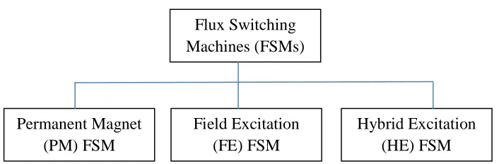
developed in recent years. They can be categorized into three groups that are Permanent
magnet (PM) FSM, field excitation (FE) FSM and hybrid excitation (HE) FSM. Among
these FSMs, the FEFSM offers advantages of low cost, simple construction and variables
flux control capabilities suitable for various performances. In this project is design study
of outer-rotor field-excitation flux switching motor (FEFSM) with a topology of 12-slot
and 10-pole configuration (12S-10P) with all active parts are located on the stator for
electric vehicle application as a low-cost of non-Permanent Magnet (PM) machine. The
performance of the proposed motor on the initial design and improved design are analysed
based on 2-D Finite element analysis (FEA). The performance of the improvement design
shows that the maximum torque is obtained 118.2165 Nm which is greater than the initial
ABSTRAK
v
TABLE OF CONTENTS
ACKNOWLEDGEMENTS ii
TABLE OF CONTENTS v
LIST OF TABLES viii
LIST OF FIGURES ix
LIST OF SYMBOLS AND ABBREVIATIONS xiii
CHAPTER 1 INTRODUCTION
1
1.1 Introduction 1
1.2 Problem Statement 2
1.3 Objectives 4
1.4 Scopes 4
CHAPTER 2 LITERATURE REVIEW 5
2.1 Background 5
2.2 Specifications of Flux Switching Machine (FSM) 5
2.3 Permanent Magnet Flux Switching Machine
(PMFSM) 6
2.4 Hybrid Excitation Flux Switching Machine
(HEFSM) 8
2.5 Field Excitation Flux Switching Machine
CHAPTER 3 METHODOLOGY 14
3.1 Initial Design for 12S – 10P 17
3.1.1 Geometry Editor 15
3.1.2 JMAG Designer 24
3.2 Improvement Design for 12S-10P 29
3.3 Design parameter and procedures for improvement
Of 12S-10P 32
CHAPTER 4 RESULT AND PERMANCES 39
4.1 Initial Design of 12S-10P Outer Rotor FEFSM 39
4.1.1 FEC Flux linkage at various FEC Current 42
4.1.2 Flux strengthening 43
4.1.3 Cogging torque characteristic with no load 44
4.1.4 Flux line of FEC at no load condition 44
4.1.5 Flux distribution 47
4.1.6 Torque versus Je at various Ja 49
4.1.7 Torque and power versus speed
characteristics 50
4.2 Final improvement design for Outer rotor FEFSM 51
4.2.1 Load analysis of the final improvement
design 52
4.2.2 Torque and power versus speed 54
4.2.3 Flux line flow 55
4.3 Summary of Initial and Improvement design of 57
vii
CHAPTER 5 CONCLUSION 59
5.1 Conclusion 59
5.2 Future Works 60
LIST OF TABLES
3.1 The design parameter for the proposed ORFEFSM 17 3.2 Initial and final design improvement of 12S-10P FEFSM 31 4.1 Initial and final design improvement parameters of
ix
LIST OF FIGURES
2.1 Classification of flux switching machine (FSMs) 6 2.2 Operation principle at two typical rotor positions for
outer rotor 7
2.3 Principle operation of PMFSM 8
2.4 Principle operation of ORHEFSM (a) θe = 0º (b) θe = 180º
more excitation, (c) θe = 0º (b) θe = 180º less excitation 9
2.5 1-phase 8S-4P FEFSM 11
2.6 3-phase 12S-8P segmental rotor 11
2.7 3-phase 24S-10P FEFSM 12
2.8 Principle operation of FEFSM (a) θe=0° and (b) θe=180° flux moves from stator to rotor (c) θe=0° and (d) θe=180°
flux moves from rotor to stator 13
3.1 Initial proposed design of Outer Rotor of 12S-10P FEFSM 15 3.2 Work flow of experiment implementation for Geometry
Editor 16
3.3 Design initial parameter defined as D1 – D9 17
3.4 Sketch the rotor at the layout 18
3.5 Create a region of rotor 18
3.6 Mirror duplication of rotor and radial duplication of 10P
of rotor 19
3.7 Draw a fraction of Stator 19
3.8 Create a region of Stator 20
3.9 Mirror duplication of Stator 20
3.10 Radial duplication of Stator 21
3.11 Draw half of Armature Coil 21
3.13 Mirror duplication and radial duplication of armature coil 22
3.14 Draw a fraction of FE Coil 23
3.15 Create a region of FE Coil 23
3.16 Mirror duplication of FE Coil 24
3.17 Mirror duplication and radial duplication of FE Coil 24 3.18 Work Flow of experiment implementation for JMAG
Designer 25
3.19 Circuit Implementation 26
3.20 Circuit Implementation for U,V and W Phase 26
3.21 The armature coil number for U phase 27
3.22 The armature coil number for V phase 27
3.23 The armature coil number for W phase 28
3.24 Direction of current for FE Coils Counter Clockwise 28
3.25 Direction of current for FE Coils 29
3.26 Design parameters of Final Improvement of 12S-10P
Outer Rotor 30
3.27 Main machine dimensions of the Final Improvement
design 12S-10P ORFEFSM 31
3.28 Torque versus stator radius D1 [mm] 33
3.29 Torque versus rotor pole depth , D2 33
3.30 Torque versus rotor pole width, D3 34
3.31 Torque versus FEC Slot Depth D6 34
3.32 Torque versus FEC slot width D7 35
3.33 Torque versus armature coils depth D8 35
3.34 Torque versus armature coils width D9 36
3.35 General flow of the design methodology 37
3.36 Simplified design of original 12S-10P Outer Rotor
FEFSM (a) initial design (b) improvement design 38 4.1 Initial separate coil setting for armature coil test and
FE Coil (12S-10P) 39
xi
4.3 Flux linkage of coil 1, 4, 7 and 10 41
4.4 Flux linkage of coil 3, 6, 9 and 12 41
4.5 All Flux linkage of phase U, V and W 42
4.6 U Phase flux linkage at various DC FEC Current density 43
4.7 JE Flux Strengthening 43
4.8 Cogging Torque of the proposed initial ORFEFSM 44 4.9 Flux Lines of the initial design of 12S-10P from FEC ,
Je=10 A/mm2 45
4.10 Flux Lines of the initial design of 12S-10P from FEC ,
Je=20 A/mm2 46
4.11 Flux Lines of the initial design of 12S-10P from FEC ,
Je=30 A/mm2 46
4.12 Flux Distribution of Je=10A/mm2 47
4.13 Flux Distribution of Je=20A/mm2 48
4.14 Flux Distribution of Je=30A/mm2 48
4.15 Torque Je at various Je of the initial design Outer
rotor FEFSM 49
4.16 Instantaneous torque profile at Ja = 30 Arms/mm2,
Je = 30A/mm2 50
4.17 Torque and Power versus speed characteristic of the initial
design FEFSM Outer Rotor 51
4.18 Instantaneous torque profile at Ja = 30 Arms/mm2 ,
Je = 30 Arms/mm2 53
4.19 Torque versus Je at various Ja 54
4.20 Characteristics Torque versus FEC current density,
Je characteristic 55
4.21 Flow of the flux 55
4.22 Ja = 30Arms/mm2, Je = 10A/mm2, T = 47.6613Nm 56
4.23 Ja = 30Arms/mm2, Je = 30A/mm2, T = 118.216N 57
4.24 Torque versus Je at maximum Ja 58
LIST OF SYMBOLS AND ABREVIATIONS
PMFSM Permanent Magnet Flux Switching Machine FEFSM Field Excitation Flux Switching Machine HEFSM Hybrid Excitation Flux Switching Machine
Nd Neodymium
Dy Dysprosium
Tb Terbium
CO2 Carbon dioxide
A.C Alternate Current
D.C Direct Current
Ja Armature Current Density
CHAPTER 1
INTRODUCTION
1.1 Introduction
The flux switching motor has three distinctive features that make its operation substantially different to that of conventional two phases short pitched switched reluctance motors and other fully pitched motors. Excitation current is supplied to both the field and armature windings constantly throughout the operation of the motor for either rotor alignment position. The field winding is excited constantly with unipolar direct current that does not require switching. The switching of the current direction in the armature winding controls the orientation of the resultant stator flux and therefore to which stator poles the rotor is attracted.
Flux switching machine can be categorized into three groups that are permanent magnet (PM) FSMs , field excitation (FE) FSMs and hybrid excitation (HE) FSMs. Both PMFSM and FEFSM has only PM and field excitation coil (FEC), respectively as their main flux sources, while HEFSM combines both PM and FECs. Among these FSMs, the FEFSM offers advantages of low cost, simple construction and variable flux control capabilities suitable for various performances. [1].
polarity of the current in the armature winding. The flux switching motor is unusual in using this principle for an electric motor.
The Outer rotor type has been the topic of much interest and research. In application with high torque requirement an Outer rotor design has several advantages compared to an inner rotor one [2].Regarding the inner rotor design, the air gap radius is limited by the space needed for the coils inside the stator and furthermore by the cooling inside the housing surrounding the laminations. The outer rotor design has the benefits that coil and cooling can be placed near the shaft, increasing the possible air gap radius [2].
1.2 Problem Statement
With increase in world population, demands toward vehicles for personal transportation have increased dramatically in the past decade. However, one of the serious problems associated with ever-increasing use of personal vehicles is the inevitable emissions which contribute to global warming. The conventional internal combustion engine (ICE) vehicles are the main contributors to this problem. According to the report in 2008 [3], seven per cent of global carbon dioxide (CO2) emissions in
year 2000 come from vehicles. The global road transport emissions are expected to keep rising proportional with the economic growth and it is projected to double by the year 2050. Because some environmental problems, such as the greenhouse effects are directly related to vehicle emissions, government agencies and organizations have developed more stringent standards for fuel consumption and emissions.
3
When using the DC motor it has many disadvantages. The overwhelming disadvantages to DC brushed machines (both series wound and other types) are the brushes themselves.Brushes ride on the commutator of the motor’s armature (the part of the motor that turns) and form a rotary switch that switches high currents to various sections of the armature coils. The mechanical nature of this rotary switching of high power produces considerable electrical arcing and also mechanical wear of the carbon brushes and the copper segments of the commutator. This arcing can ignite flammable vapors if they are present around the motor. Although this condition is generally unlikely, the possibility of such ignition usually excludes brushed motors from commercially manufactured vehicles. In contrast, an AC induction motor, which has no brushes, completely eliminates this risk.
In other circumstances, an increase in annual usage of rare-earth magnet have increased the price of rare-earth metals not only Neodymium (Nd) but also Dysprosium
(Dy) and Terbium (Tb) which are indispensable to provide the rare-earth magnet with
high coercivity as the additives. According to the report released by Mineral Resource Information Centre affiliated to Japan Oil, Gas and Metals National Corporation, a future prospect was summarized such that the production amount of Nd2Fe14B would
reach at 1,500 tons only in HEV applications in 2011 and the corresponding usage of 70 tons Dysprosium would be serious problem from the viewpoints of cost, security and undersupply. Therefore, the continuous research and development of permanent magnet machines with less or no rare-earth materials would be very important.
1.3 Objectives
The objectives of this project is
i) To design the Outer Rotor Field Excitation Flux Switching Motor for
Electrical Vehicles application with 12S-10P
ii) To analyse the performances of the design motor under no load, load, torque
and power
iii) To improve the initial design 12S-10P until the target performances are
achieved.
1.4 Scopes
i) This project is design by using JMAG Design Version 13.0 software.
ii) The designed is target power and torque is setting respectively 10kW and 78Nm/80kg for improvement design.
CHAPTER 2
LITERATUTRE REVIEW
2.1 Background
The concept of flux switching permanent magnet (FSPM) has published in the 1950s. Over the last ten years, many novel and new FSMs topologies have been developed for various applications, ranging from low cost domestic appliances, automotive, wind power, aerospace, and etc [6].
2.2 Classifications of Flux Switching Machine (FSM)
Fig. 2.1: Classification of flux switching machine (FSMs)
2.3 Permanent Magnet Flux Switching Machine (PMFSM)
The permanent magnet flux-switching machines (PMFSM) have a short history and have been studied for several decades. And is a relatively new category of electric machines. The basic model of PMFSM was described in [7], where Rauch and Johnson proposed a new type of motor with permanent magnets placed in the stator. Generally, such machines have a salient pole rotor and the PMs which are housed in the stator.
The PMFSM is very similar to the doubly salient permanent magnet (DSPM) machine or to the flux reversal machine (FRM) [8] [9].
However, conventional PMFSMs have a relatively poor flux weakening performance due to constant magnetic flux that required armature winding current control to operate in the flux weakening region. By applying negative d-axis current, the PM flux can be counteracted hence reducing the magnetic flux density. However, the disadvantages of increase in copper loss which significantly reduce the efficiency, and possible irreversible demagnetization of the PM are difficult to overcome. To provide further attractive characteristics, a new structure of 12S-10P PMFSM with additional field excitation coil (FEC) has been proposed [10].
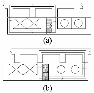
The basic operation principle of the outer-rotor PMFS machine is illustrated as in Fig 2.2. The upper part is the laminated rotor similar to that of the SR machine. The lower part is the stator, where the PM and the armature winding are located. The PM is inset between two stator poles, and establishes a self-excited flux with a fixed direction within itself. In Figure 2.2 (a), the two rotor poles align with the two stator teeth which
7
[image:18.595.245.399.223.375.2]are embraced by a concentrated winding coil. The PM flux which is linked in the coil goes out of the coil and into the rotor pole. When the rotor moves to the left, the rotor pole leaves the current stator pole and aligns with the next stator tooth which belongs to the same coil, as shown in Figure 2.2 (b). As the rotor moves, both the magnitude and polarities of the flux-linkage in the windings will vary accordingly [11].
Fig. 2.2 : Operation principle at two typical rotor positions for outer rotor
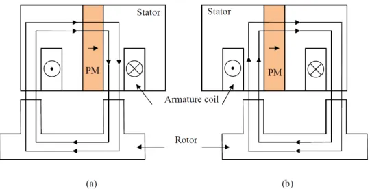
Fig. 2.3: Principle operation of PMFSM
2.4 Hybrid Excitation Flux Switching Machine (HEFSM)
Hybrid excitation flux switching machines (HEFSMs) are those which utilize primary excitation by PMs as well as DC FEC as a secondary source. Conventionally, PMFSMs can be operated beyond base speed in the flux weakening region by means of controlling the armature winding current. By applying negative d-axis current, the PM flux can be counteracted but with the disadvantage of increase in copper loss and thereby reducing the efficiency, reduced power capability, and also possible irreversible demagnetization of the PMs. Thus, HEFSM is an alternative option where the advantages of both PM machines and DC FEC synchronous machines are combined. As such HEFSMs have the potential to improve flux weakening performance, power and torque density, variable flux capability, and efficiency which have been researched extensively over many years [12].However, Hybrid Excitation FSM has more complicated design compare than permanent magnet FSM and Field Excitation FSM.
The inner stator consists of the armature windings, followed by the FECs in the middle layer, while the PMs are placed in outer stator as discussed in [13] [14]. However, the machine has low torque density and long end winding for the DC FECs, which overlaps the armature windings, and increase copper loss.
9
[image:20.595.199.461.385.613.2]shown in the upper part, while the stator that consists of PMs, FECs, and armature coils are located in the lower part. The PM and FEC are placed between two stator poles to generate excitation fluxes that create the term of “hybrid excitation flux”. Fig. 2.4 (a) and (b) demonstrate the flux generated by PM and FEC flow from the stator into the rotor and from the rotor into the stator, respectively, to produce a complete one flux cycle. The combined flux generated by PM and FEC established more excitation fluxes that are required to produce higher torque of the motor. When the rotor moves to the right, the rotor pole goes to the next stator tooth, hence switching the magnitude and polarities of the flux linkage. The flux does not rotate but shifts clockwise and counter clockwise in direction with each armature current reversal. According to Figs. 2.4 (c) and (d), only the PM flux flows from the stator into the rotor and from the rotor into the stator, respectively, while the FEC flux is only circulating on its particular winding slots. This condition establishes less excitation flux and generates less torque [15].
2.5 Field Excitation Flux Switching Machine (FEFSM)
The concept of the FEFSM involves changing the polarity of the flux linking with the armature coil windings, with respect to the rotor position. The design principle is explained in [16], and the single-phase 8S-4P FEFSM has achieved higher output power density and much higher efficiency when compared with the induction machine (IM). However, the 1-phase FEFSMs suffer with problems of low starting torque, large torque ripple, fixed rotating direction, and overlapped windings between armature coil and FEC.
To improve the performances, a 3-phase 12S-8P with segmental rotor and 24S-10P FEFSMs have been developed as shown in Figs. 2.6 and 2.7, respectively. For 12S-
11
[image:22.595.241.407.109.282.2]
Fig. 2.5: 1-phase 8S-4P FEFSM.
[image:22.595.232.403.352.528.2]Fig. 2.7: 3-phase 24S-10P FEFSM
13
Fig. 2.8: Principle operation of FEFSM (a) θe=0° and (b) θe=180° flux moves from stator to rotor (c) θe=0° and (d) θe=180° flux moves from rotor to stator
Overview of various FSM, design and performance features, various machine topologies, variable flux capability as well as their relationships with doubly-salient PM machines and flux reversal PM machines are also been discussed in [20]. The advantages of FSM compared than Induction Motor, Synchronous motor, Switch reluctance motor are listed below
i. Simple and robust rotor structure suitable for high speed applications ii. Easy to manage magnet temperature rise as all active parts are located in
the stator.
iii. Flux focusing / low cost ferrite magnets can also be used.
CHAPTER 3
METHODOLOGY
3.1 Initial Design for 12S-10P
15
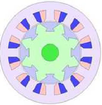
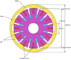
Fig. 3.1:Initial proposed design of Outer Rotor of 12S-10P FEFSM
3.1.1 Geometry Editor
The design requirements, restrictions and specifications for proposed ORFEFSM is 12 slot and 10 poles. The corresponding electrical restrictions armature coils current is 360A respectively, while the limit of both armature current density, Ja and FEC current
Fig. 3.2: Work flow of experiment implementation for Geometry Editor
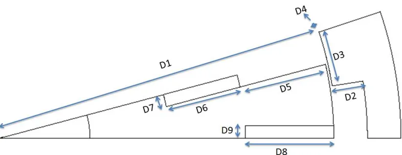
In this design study, the motor parameters are divided into two groups, namely, those related to stator iron core and rotor iron core. On the stator iron core part, it is divided into two components which are the FEC slot shape and armature slot shape. The rotor parameters involved are the stator radius (D1), rotor pole depth (D2), and rotor pole
arc width (D3). The distance between airgap and rotor is (D4),Air slot (D5), while for
the FEC slot parameters are FEC slot depth and FEC slot width, (D6) and (D7)
respectively. Finally, the armature coil parameters are armature coil slot depth (D8) and
the armature coil slot width (D9). The motor design parameters, from D1 to D9 are
17
[image:28.595.119.530.117.276.2]Fig. 3.3: Design initial parameter defined as D1 – D9
Table 3.1 : The Design Parameter for the proposed ORFEFSM
Parameter Description Initial
D1 Stator radius 111
D2 Rotor Pole depth (mm) 9.2
D3 Rotor pole arc width ( ˚ ) 11
D4 Distance between airgap and rotor (mm) 0.8
D5 Air slot (mm) 30
D6 FEC slot depth (mm) 25
D7 FEC slot width (mm) 4.125
D8 Armature coil slot depth (mm) 29
D9 Armature coil slot width (mm) 4.125
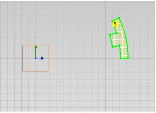
Fig. 3.4: Sketch the rotor at the layout
The other part of the rotor can be finish by using the toolbar at the geometry editor software. Then create the region as shown Fig. 3.5.
Fig. 3.5: Create a region of rotor
[image:29.595.191.461.424.613.2]19
Fig. 3.6:Mirror duplication of rotor and radial duplication of 10P of rotor
For the stator design, initially determine the parameters of the stator. Draw 90 ˚/half of the stator slot as shown in Fig.3.7.
[image:30.595.189.462.440.628.2]Repeat the step of rotor drawing to complete the stator drawing structures. Refer Fig. 3.8
Fig. 3.8:Create a region of Stator
[image:31.595.174.455.368.558.2]21
Fig. 3.10:Radial duplication of Stator
After that, to complete the drawing of armature coil by referring to Fig. 3.11 until Fig 3.13 respectively.
[image:32.595.183.455.427.554.2]Fig. 3.12: Create a region of Armature Coil
Fig. 3.13:Mirror duplication and radial duplication of armature coil
[image:33.595.189.435.302.530.2]23
Fig. 3.14:Draw a fraction of FE Coil
[image:34.595.193.446.333.512.2]Fig. 3.16: Mirror duplication of FE Coil
Fig. 3.17:Mirror duplication and radial duplication of FE Coil
3.1.2 JMAG Designer
[image:35.595.198.444.319.547.2]61
REFERENCES
[1] S. Erwan, "Investigation on Flux Characteristics of Field Exicitation Flux Switching Machine with Single FEC Polarity," Procedia Technology 8C, pp. 561-567, 2013.
[2] D. Martin and W. D. Rik, "Comparison of Outer and Inner Rotor Switched Reluctance Machines," IEEE PEDS, 2007.
[3] J.King, "The King Review of low carbon cars of low carbon cars-Part II: recommendations for action," March 2008. [Online]. Available: www.hm-treasury.gov.uk/king.
[4] S. Niku, Introduction to Robotics: Analysis, Control Application 2nd Edition, 280: John Wiley & Sons, Inc, 2011.
[5] R. S. Carrow, Electrician's technical references : Variable frequency drives, 45: Delmar Thomson Learning, 2001.
[6] Z.Q Zhu and J.T Chen, "Advanced Flux switching Permanent Magnet Brushless Machines," IEEE Transactions on Magnetics , vol. 46, no. 6, June 2010.
[7] Rauch SE and Johnson LJ, "Design principles of flux switching alternators," AIEEE
Trans, vol. 74III, pp. 1261-1268, Jan 1955.
[8] C. W. S. A. N. I. Boldea, "Design of a three-phase flux," EMPS, vol. 27, pp. 849-863, 1999.
[9] R.P. Deodhar, S.Andersson, I.Boldea and T.J.E Miller, "The flux reversal machine : A new brushless doubly-salient permanent-magnet machine," IEEE Trans. Ind
Appl, vol. 33, no. 4, pp. 925-934, Jul/Aug 1997.
Coil," Journal of Electrical System, pp. 425-432, 2012.
[11] W.Fei, P.C.K Luk, J.Shen and Y.Wang, "A Novel Outer-Rotor Permanent-Magnet Flux-Switching Machine for urban electric vehicle propulsion," IEEE International
Conference on Power Electronics Systems and Applications, pp. 1-6, May 2009.
[12] Y.Amara, L.Vido, M.Gabsi, E.Hoang, M.Lecrivain and F.Chabot, "Hybrid Excitation Synchronous Machines: Energy Efficient Solution for Vehicle Propulsion," IEEE Vehicle Power and Propulsion Conference, pp. 1-6, Sept. 2006.
[13] Y.Liao, F.Liang and T.A Lipo, "A novel permanent magnet motor with doubly salient structure," Proc. Conf. Rec. IEEE IAS Annual Meeting, vol. 31, no. 5, p. 308–314, October 1992.
[14] Chau, K.T, Ming Cheng, Chan and C.C, "Nonlinear magnetic circuit analysis for a novel stator doubly fed doubly salient machine," IEEE Trans. Magnetics, vol. 38, no. 5, p. 2382–2384, Sep. 2002.
[15] M.Z Ahmad, E.Sulaiman, Z.A. Haron and T.Kosaka, "Impact of rotor pole number on the characteristics of outer rotor hybrid excitation flux switching motor for In wheel Drive EV," Procedia technology , pp. 581-588, 2013.
[16] B. JF, "Design of high-power density and relatively high efficiency flux-switching motor," IEEE Trans. Energy Convers, pp. 416-424, JUNE 2006.
[17] M. B. A. A. Zuhu A, "A wound field three phase flux switch motor with all excitation sources on the stator," IEEE Trans Ind. Appl, pp. 2363 - 2371, Nov 2010.
[18] Chen J.T, Zhu, Z.Q, Iwasaki S. and R. Deodhar, "Low Cost flux switching brushless AC machines," Proc IEEE Vehicle Power and Propulsion Conf, Sept 2010.
[19] C.Pollock, H.Pollock, R. Barron, R.Sutton, J.Coles, D.Moule and A.Court, "Flux-switching motors for automotive applications," IEEE Trans. Ind. Appl., pp. 1177-1184, Sep/Oct 2006.
[20] Z. Zhu, "Switched flux permanent magnet machines: Innovation continues," Proc