Parametric Study on Anti-Vortex Film Cooling Hole Arrangements
Kamil Abdullah
1, a *, Hazim Fadli Aminnuddin
2,aand Akmal Nizam Mohammed
3,a1
Center for Energy and Industrial Environmental Studies Faculty of Mechanical and Manufacturing
Universiti Tun Hussein Onn Malaysia 86400 Parit Raja, Johor MALAYSIA
a
[email protected], [email protected], [email protected] Keywords: anti-vortex film cooling, counter rotating vortex pair, film cooling effectiveness
Abstract. Film cooling has been extensively used to provide thermal protection for the external
surface of the gas turbine blades. Numerous number of film cooling holes designs and arrangements have been introduced. The main motivation of these designs and arrangements are to reduce the lift-off effect cause by the counter rotating vortices (CRVP) produce by cylindrical cooling hole. One of the efforts is the introduction of newly found anti-vortex film cooling design. The present study focuses on anti-vortex holes arrangement consists of a main hole and pair of smaller holes. All three holes share a common inlet with the outlet of the smaller holes varies base on it relative position towards the main hole. Three anti-vortex holes arrangements have been considered; downstream anti-vortex hole arrangement (DAV), lateral anti-vortex hole arrangement (LAV), and upstream anti-vortex hole arrangement (UAV). In addition, a single hole (SH) film cooling has also been considered as the baseline. The investigation make used of ANSYS CFX software ver. 14. The investigations are made through Reynolds Average Navier Stokes analyses with the application of shear k-ε turbulence model. The results show that the anti-vortex designs produce significant improvement in term of film cooling effectiveness and distribution. The LAV arrangement shows the best film cooling effectiveness distribution among all considered cases and is consistent for all blowing ratios (BR). The results also unveil the formation of new vortex pair on both side of the primary hole CRVP. Interaction between the new vortices and the main CRVP structure reduce the lift off explaining the increased lateral film effectiveness.
Introduction
Gas turbine has become one of the main power resources especially to the aeronautics and industrial sectors. The manufactures are competing to produce higher efficiency gas turbine. One of the most common routes to increase the efficiency of gas turbines is by increasing the turbine inlet temperature. The modern gas turbine often operates at a very high temperature which exceeds the limits of the gas turbine components operating temperature. This high temperature will reduce the life span of turbine components especially the rotor and stator blade which have a direct contact with the hot flow stream. To enable turbine components to operate at this high temperature, sophisticated cooling system is required which includes film cooling.
information on the effects of geometrical parameters on the aerodynamic and thermal characteristics of the film cooling. Figure 1 shows the considered geometrical arrangements considered in the present study.
Literature Review
[image:2.595.61.279.131.275.2]The modern gas turbine operates at the temperature of 1600K, which exceeds the metallurgical limit of the gas turbines components material. This high temperature will expose the turbine components especially the stator and rotor blades to extreme thermal stresses. By exceeding their metallurgical limits, the durability of a turbine components are significantly compromised, decreasing its life by 50% with a 10˚C increase in temperature above the design operational limit [1].One way to sustain the turbines blade is by the implementation of film cooling. The film cooling technique is now becoming a standard method to provide thermal protection to the turbine blade. As the coolant injected, it will provide a protective layer to the surface; reducing the surface temperature. However, the method brings together a new set of problem. As the coolant and the hot gas mainstream intersect, it produces a complex vortex system which has been studied by Kelso et al. [2]. One of these vortices is the counter-rotating vortex pair (CRVP). The formation of CRVP is known to has enormous effects on the film cooling performance [3]. The previous studies proved that the formation of CRVP will reduces the film cooling effectiveness as the vortex pair pulls hot stream gas into the near wall region. In order to surpass this problem, fan-shaped hole has been introduced. This shaped hole is designed to have a larger exit area expected to reduce the jet momentum at the exit hence hindering the formation of CRVP. Extensive study on shaped film cooling hole has been conducted by Goldstein et al. [4]. The study reveals that the enlargement of the hole exits does not only reduce the exiting jet momentum but also alter the vortices structure of the jets. In a quest for higher cooling performances and lower manufacturing costs, compound angle injection has been introduced. The difference between the compound angle and normal film cooling hole is, the hole exit will not be parallel to the mainstream flow direction, instead it will be inclined to associated compound angle. Schmidt et al. [5] performed studies on film cooling effectiveness and heat transfer distribution for a row of round and shaped film cooling holes with compound angle orientation to mainstream. The compound angle cases have been observed to be superior in terms of film cooling effectiveness at all blowing ratio. However, among all the considered cases, shaped hole producing better-quality film cooling effectiveness mainly due to better coolant distribution in the lateral direction and at near the hole. Heidmann et al. [6] have proposed new cooling hole design namely anti-vortex film cooling hole. The anti-vortex cooling hole consists of single hole which accompanied with two sister holes. These two sister holes are expected to produce their own vortices which will neutralize the vortices produced by the main hole. It is reported that the lift off effect triggered by the CRVP of the main hole is reduced. Consequently, it improves the film effectiveness compared to a standard hole case for the same blowing ratios. Dhungel et al. [7] further confirm the superiority of the anti-vortex cooling hole by investigating it performance four different blowing ratios. The results indicate better downstream and lateral film coverage leads to improved overall film cooling effectiveness. Schulz et al. [8] have done the experimental investigations of an anti-vortex film cooling geometry under low and high turbulence conditions. Similar observations have been reported as the previous results [6, 7]. It is suggested that the new hole design reduces the jet exit momentum, preventing jet detachment leads to significant improvement in film cooling effectiveness.
Figure 1: Considered Arrangements of Anti-Vortex Film Cooling Hole
Methodology
Computational Domains. The present study focuses to investigate the effect of anti-vortex
hole arrangements involving three
arrangements; a) upstream anti-vortex hole arrangement (UAV), b) lateral anti-vortex hole arrangement (LAV), and c) downstream anti-vortex hole arrangement (DAV). On top of the aforementioned cases, a cylindrical film cooling case has also been considered as a baseline case. Figure 2 shows the computational domain involved in the present study together with the geometrical details. The computational domain consists of main film cooling hole inclined at θ = 35° toward the main stream direction. The main hole accompanied with three different sets of sister hole; UAV, LAV and DAV. The distance between the main hole center and the sister hole center is at 1D in the lateral direction for all configurations, meanwhile 1D to the upstream and 1D to the downstream for UAV and DAV arrangements respectively in the mainstream direction. The LAV configuration has the same center line in the mainstream directions as the single hole. Prior to the analyses, mesh dependency test has been carried out to ensure the accuracy of the numerical procedure. All of the models consist of nodes number not less than 33000.
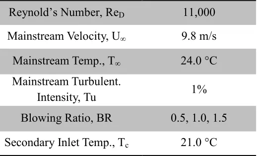
Numerical Setup. The present numerical investigations were carried out through ANSYS CFX software. Reynolds Average Navier Stokes analysis has been applied with the employment of k-ɛ turbulence model. The boundary conditions applied in the present study make used most of the one in the work of Schulz et al. [5] as shown in Table 1. The secondary mass flow rate for the anti-vortex hole have been determine with the assumption that all the cooling holes to have the same blowing ratio and the sum of the required mass flow rate of each hole have been applied at the secondary inlet of the computational domain.
Result and Discussion
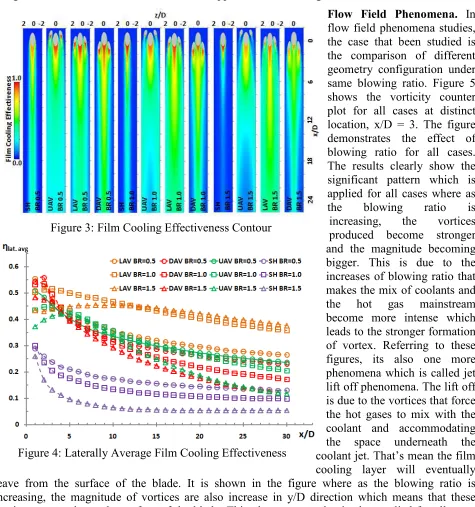
Film Cooling Effectiveness. Figure 3 demonstrates the film cooling effectiveness distribution contour for all cases in for blowing ratio, BR = 0.5,1.0 and 1.5.. All figures are shown in z/D vs x/D axis. In general, the anti-vortex design shows a significant improvement compared to the single hole design. One reason for this particular result is due to the neutralization of main hole CRVP by the additional holes vortices. However, among anti-vortex design, Lateral Anti-Vortex (LAV) shows the best coverage for all blowing ratio proposed. The distribution of film cooling for LAV design is in uniformly order. Differ from LAV, UAV and DAV design which the film cooling layer only focused either in the sideway or only for centerline. Focusing on blowing ratio, all cases except LAV case show a distinct pattern of distribution where as the blowing ratio is increasing, the area of distribution decreases. Meanwhile for LAV case, the results promotes that the area of distribution is constant with the effectiveness increases. Figure 4 proves this particular result where it shows the topology of lateral average film cooling effectiveness across the x/D. The graph shows that the
Reynold’s Number, ReD 11,000
Mainstream Velocity, U∞ 9.8 m/s
Mainstream Temp., T∞ 24.0 °C
Mainstream Turbulent.
Intensity, Tu 1%
Blowing Ratio, BR 0.5, 1.0, 1.5
[image:3.595.286.545.414.571.2]Secondary Inlet Temp., Tc 21.0 °C
Table 1: Details on the Boundary Condition Figure 2: Geometrical Details of the
Computational Domain
highest effectiveness is produced by LAV design. Meanwhile the UAV and DAV designs show no significant differences except DAV produces better effectiveness at the near exit hole region. In comparison for single hole and anti-vortex designs, this graph clearly shows that the anti-vortex design demonstrate much more effective and applied for all blowing ratio.
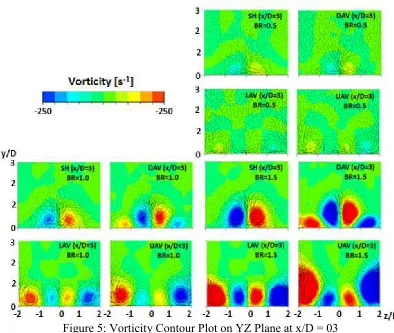
Flow Field Phenomena. In flow field phenomena studies, the case that been studied is the comparison of different geometry configuration under same blowing ratio. Figure 5 shows the vorticity counter plot for all cases at distinct location, x/D = 3. The figure demonstrates the effect of blowing ratio for all cases. The results clearly show the significant pattern which is applied for all cases where as
the blowing ratio is
increasing, the vortices produced become stronger and the magnitude becoming bigger. This is due to the increases of blowing ratio that makes the mix of coolants and the hot gas mainstream become more intense which leads to the stronger formation of vortex. Referring to these figures, its also one more phenomena which is called jet lift off phenomena. The lift off is due to the vortices that force the hot gases to mix with the coolant and accommodating the space underneath the coolant jet. That’s mean the film cooling layer will eventually leave from the surface of the blade. It is shown in the figure where as the blowing ratio is increasing, the magnitude of vortices are also increase in y/D direction which means that these vortices start to leave the surface of the blade. This phenomenon also is also applied for all cases studied.
Conclusion
The present study involved an numerical investigation of an anti-vortex cooling hole design. This numerical investigation is made used of ANSYS CFX ver. 14. RANS – Reynolds Averaged Navier Stokes has been used for the simulation involving the Reynolds number, Re = 11000, blowing ratio BR = 0.5,1, 1.5 and also four different film cooling hole design; Single hole, Upstream anti-vortex, Downstream anti-vortex and Lateral anti-vortex. Conclusions of the present study are as follows:
i. All results show the significant improvement of film cooling effectiveness distribution of anti-vortex design in comparison with the single hole design.
[image:4.595.63.538.125.632.2]Figure 4: Laterally Average Film Cooling Effectiveness Figure 3: Film Cooling Effectiveness Contour
ii. In comparison of anti-vortex cooling hole design, Lateral Anti-Vortex (LAV) shows the best effectiveness and it is also consistent in all number of blowing ratio.
iii. As the blowing ratio increased, the formation of vortices is also become stronger and bigger. iv. Due to the increased of blowing ratio, the magnitude of vortices are also increased that
[image:5.595.97.491.150.483.2]eventually leads to the jet lift off phenomenon.
Figure 5: Vorticity Contour Plot on YZ Plane at x/D = 03
References
[1] Han, J.C., Dutta, S., & Ekkad, S.V., 2000, “Gas Turbines Heat Transfer and Cooling Technology,” New York: Taylor and Francis.
[2] Kelso, R.M., Lim, T.T., Perry A.E., 1996, ‚‘‘An Experimental Study of Round Jets in Cross-Flow“ Journal of Fluid Mechanics, Vol. 306, pp: 111-144.
[3] Mizukami, S., Teramoto, S. & Nagashima, T., 2007. “Numerical Study on the Three-Dimensional Flow Structure Around a Film Cooling Hole,” Proceeding of International Gas Turbine Congress 2007, Tokyo, Japan, pp. 2007-TS-111.
[4] Goldstein, R.J., Eckert, E.R.G., Burggraf, F., 1974, “Effects of Hole Geometry and Density on Three-Dimensional Film Cooling,” International Journal of Heat and Mass Transfer, Vol. 17, pp. 559-607.
[5] Schmidt, D. L., Sen, B., Bogard, D. G., 1996, “Film Cooling With Compound Angle Holes: Adiabatic Effectiveness,” Journal of Turbomachinery, 118/807.
[6] Heidmann, J.D., & Ekkad, S.V. (2008). “A Novel Anti-Vortex Turbine Film-cooling Hole Concept.” Journal of Turbomachinery, Vol. 131, pp. 021007-1.
[7] Dhungel, A., Lu, Y., Phillips, W., Ekkad, S.V., Heidmann, J., 2009, “Film Cooling From a Row of Holes Supplemented With Anti-Vortex Holes.” Journal of Turbomachinery, Vol. 131, pp. 021007-1.
[8] Schulz, S., Maier, S., Bons, J.P., 2012. “An Experimental Investigation of An Anti-Vortex Film Cooling Geometry Under Low and High Turbulence Conditions,” Proceeding of ASME Turbo Expo 2012, pp. GT2012-69237.