Advanced Technique to Improve Dynamic Response of a
Direct Torque Controlled Induction Motor
Alekya N, Mohan B
II/II M. Tech, Department of Electrical and Electronics Engineering P.V.P. Siddhartha Institute of Technology, Vijayawada, Andhra Pradesh, India
Asst. Professor, Department of Electrical and Electronics Engineering P.V.P. Siddhartha Institute of Technology, Vijayawada, Andhra Pradesh, India
Abstract- Direct torque control based on space vector modulation (SVM-DTC) preserve DTC transient merits, furthermore, produce better quality steady-state performance in a wide speed range. The SVM-DTC system based on input-output linearization technique for induction machine drives is developed in this paper. A sliding-mode observer for estimating flux is introduced. The observer is inherently sensor less because they do not employ the rotor speed adaptation, and thus they are insensitive to speed estimation errors. Moreover, the observer is extremely robust. The simulations of conventional DTC and the proposed control topologies are given and discussed. It is concluded that the proposed control topology outperforms the conventional DTC in reducing torque ripple and parameter robust.
Index Terms- Direct torque control ,Sliding-Mode observer, Input-output Linearization.
I. INTRODUCTION
n high-performance variable-speed drive applications for induction machines, there are two most popular control strategies: field-oriented control (FOC) and direct torque control (DTC) [1,2]. Both of them can decouple the interaction between flux and torque control, and provide good torque response in steady state and transient operation conditions.
Unlike field-oriented control, direct torque control does not require coordinate transformation and any current regulator. It controls flux and torque directly based on their instantaneous errors [3]. In spite of its simplicity, direct torque control is capable of generating fast torque response [4]. In addition, direct torque control minimizes the use of machine parameters [5], so it is very little sensible to the parameters variation.
One of the disadvantages of conventional DTC is high torque ripple [6]. Several techniques have been developed to reduce the torque ripple. One of them is duty ratio control method. In duty ratio control, a selected output voltage vector is applied for a portion of one sampling period, and a zero voltage vector is applied for the rest of the period. The pulse duration of output voltage vector can be determined by a fuzzy logic controller [7]. In [8], torque-ripple minimum condition during one sampling period is obtained from instantaneous torque variation equations. The pulse duration of output voltage vector is determined by the torque-ripple minimum condition. These improvements can
greatly reduce the torque ripple, but they increase the complexity of DTC algorithm. An alternative method to reduce the ripples is based on space vector modulation (SVM) technique [9,10]. At each cycle period, a preview technique is used to obtain the voltage space vector required to exactly compensate the flux and torque errors. The required voltage space vector can be synthesized using SVM technique. The torque ripple for this SVM-DTC is significantly improved.
An approach for conventional DTC flux estimation is based on the voltage model integrators. The pure integrator has the following drawbacks. 1) input dc offset leads the output into saturation limit; 2) initial condition error produces a constant output dc offset; and 3) it is very sensitive to stator-resistance identification, especially at low speeds. Usually, adaptive observers employ the time-variable full order IM model to estimate the flux. At least one equation of the model contains a speed-dependent term, and the observer must always be speed adaptive. In most cases, the rotor speed calculation is the last step of the estimation process. Thus, the estimated speed is always affected by cumulative errors, noises, and time delays. This in accurate speed estimation is feed back to the adaptive flux observer and then the accuracy of flux and speed estimator may progressively worsen. Undesirable effects, such as limit cycles, higher noise sensitivity, or delays may occur and deteriorate the system overall performances, especially at very low stator frequencies, where the fundamental excitation is low. A solution for this is to use non adaptive observers. A distinct approach for sensor less flux estimation is based on full-order sliding-mode observers (SMOs). The sliding mode control theory presents promising features: disturbances rejection, strong robustness to parameter deviations, system order reduction [11]. Solutions using speed-adaptive SMOs are proposed in [12, 13]. These observers use sliding mode surfaces that combine the stator-current errors within the flux estimation. They are speed adaptive, with the aforementioned disadvantages. Accurate model parameters are required, especially in low-speed operation; therefore, online parameter identification is employed. In this paper, SVM-DTC scheme based on input output linearization technique for induction machine drives is developed. Furthermore, a sliding-mode observer is used to estimate flux is introduced. The observer is inherently sensor less because it does not employ the rotor speed adaptation, and thus they are insensitive to speed estimation errors. Moreover, the observer is extremely robust. Simulation results with a sensor
less direct-torque-controlled (DTC) IM drive using the observer prove the estimation accuracy, robustness, and high-dynamic performance in wide speed range. It is shown that the observer is able to sustain accurate very low-speed operation.
The remainder of this paper is organized as follows. The proposed SVM-DTC principle based on input-output linearization technique is described in Section II. In Section III, a sliding-mode observer for estimating flux is introduced. Simulation results of the proposed scheme are given and discussed in Section IV. Finally, conclusions are summarized in Section V
II.
SVM-DTC BASED ON INPUT-OUTPUT
LINEARIZATION
Under assumption of linearity of the magnetic circuit neglecting the iron loss, a three-phase IM model in a stationary D-Q axes reference with stator currents and flux are assumed as state variables, is expressed by:
iD = -[1/α(Rs/Ls+Rr/ Lr)] iD -ωm.iQ+[Rr/( αLsLr)].ΨD
+ [ωm/ α Ls]. ΨQ+ [1/ α Ls].uD
(1)iQ=-[1/α(Rs/Ls+Rr/Lars)] iQ +ωm.iD+[Rr/( αLsLr)].ΨQ
- [ωm/ α Ls]. ΨD+[1/ α Ls].uQ
(2)Ψ
D= u
D- R
s.i
D (3)ΨQ= uQ- Rs.iQ
(4)where
ΨD
,ΨQ
,u
D ,u
Q ,i
D ,i
Qare respectively the d-q axes of the stator flux, stator voltage and stator current vectorcomponents,ωm
is the rotor electrical angular speed, Ls, Lr, Lm are the stator, rotor, and magnetizing inductances, respectively,α=1-(Lm
2/LsLr)
and Rs, Rrare the stator androtor resistances, respectively.
Also, the motor mechanical equation is
T
o=T
L+Bω+J.
(5)
where,
ω
is the rotor mechanical angular speed, TL is the motor load torque, J is moment of inertia, B is factor of friction coefficient and Te is the motor generated torque which is defined by: [image:2.612.319.567.58.249.2]T
e=
p
n
Ψs
*
i
s =
p
n (
ΨD
i
Q-
ΨQ
i
D)
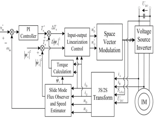
(6) where, pn is the number of pole pairs.Fig 1: The block diagram of the DTC-SVM system
Unlike field-oriented control, direct torque control does not require coordinate transformation and any current regulator. It controls flux and torque directly based on their instantaneous errors. In spite of its simplicity, direct torque control is capable of generating fast torque response. In addition, direct torque control minimizes the use of machine parameters, so it is very little sensible to the parameters variation. However, there is only one voltage vector can be selected to minimizes the torque error and flux error in one sampling period and normal voltage source inverter can only provide six voltage vector. So it is impossible to minimizes the torque error and flux error. The SVM principle based on the switching between two adjacent active vectors and a zero vector during one switching period can synthesize arbitrary voltage vector, which can overcome the drawback of conventional DTC. The proposed DTC-SVM system based on feedback linearization is illustrated in fig.1.
The DTC-SVM scheme is developed based on the IM torque and the square of stator flux modulus as the system outputs; stator voltage components defined as system control inputs and stator currents as measurable state variables.
Define the controller objectives e1 and e2 as
e1=
T
o-T
oref (7)e2=
| Ψs
2|-| Ψsref
2|
(8) From (1-6),=
p
n(
.iQ+ ΨD.-
.iD- ΨQ.)
=
p
n[ c(ΨD.iQ- ΨQ.iD) + ωm(ΨD.iD+ ΨQ.iQ)
- (ωr/αLs) | Ψs
2| + ( iQ- ΨQ/ αLs) uD*
-(iQ- ΨD/ αLs) uQ*]
(9)|
Ψ
|
(
Ψ
Ψ
)
ΨD.uD*+ ΨQ.uQ*)
Equations (9) and (10) in the form is
(
) (
)
+D
(
)
(11)
where,
g1=
p
n[c(ΨD.iQ- ΨQ.iD) + ωm(ΨD.iD+ ΨQ.iQ)- (ωr/αLs) | Ψs
2|]
g2=2Rs(ΨD.iQ+ ΨQ.iD)
[
Ψ
Ψ
α
Ψ
Ψ
α
]
Using the IM model,
Ψ
α
α
Ψ
(12)
Linking (9-12),
α
)
p
n (ΨdΨD-
ΨqΨQ)
=
α
).
p
n(ΨΨS) (13)
=
α
).
p
n| Ψr|| Ψs|. Cos (Ψ
Ψ
)
From (13), D is a nonsingular matrix since the inner product of stator flux vector and rotor flux vector can not be physically zero. Based on input-output feedback linearizing, the following control inputs are introduced:
(
) (
)
(14)
where, ux, uy are the auxiliary control inputs and are defined
based on the pole placement concept of the linear control systems so that
(15)
Where c1 and c2 are positive constants.
The SVM unit receives the D-Q components of thereference voltage vector uD and uQ*in a stator flux reference frame as inputs and generates the inverter’s command signals.The reference voltage vector uref=uD +j.uQ*derived from (14) can be produced by adding two adjacent active vectorsuk(uk,αk) and
uk+1(uk+1,αk+1),(αk+1=αk+π/3)and, if necessary, a zero vector
u0(000) or u7(111), which is illustrated in fig. 2.
The duty cycles t1 and t2 for each active vector are the solutions of the complex equation.
√
.
⁄
.
| |
(16)
√
.
⁄
.
| |
(17)where, UDCis the dc-link voltage.
The duty cycle for the zero vectors is the remaining time inside the switching period T.
(18)
Fig.2 synthetically reference voltage vectors
The sequence guarantees that each transistor inside the inverter switches once and only once during the SVM switching period. A strict control of the switching frequency can be achieved by this approach. Fig.3 shows the command signals for the inverter when the vectors u1(100) or u2(110)and zero vectors u0(000) or
u7(111) are applied.
Fig.3 SVM voltage vector timing
III. SLIDING-MODESTATORFLUXOBSERVER
The IM state model with stator-flux ψs and rotor-flux ψras state variables, in arbitrary reference frame rotating with angular speed ωe is given by
[
]
(19)
(
]
Where, Ts= Ls/Rs, Tr= Lr/Rr.
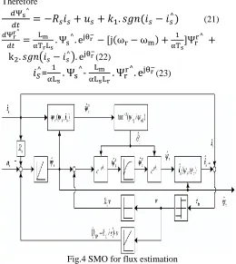
A. SMO for Flux Estimation
The full-order SMO for flux estimation is shown in Fig. 4, where the basic SMO solution has k1I = 0. It is a sensor less
Therefore
(21)
(
)
(22) [image:4.612.34.294.62.353.2]=
-
(23)
Fig.4 SMO for flux estimation
where, ωris the rotor-flux speed, k1, k2 are the observer gains, and “ˆ” marks estimated variables or parameters.
Apparently, (22) employs the speed. In fact, there is no need, neither for ωm, nor for ωr, since in rotor-flux reference, the imaginary component of (22) is zero and its real component is
+ Re (
(24)
The coordinate transformations require the angle
where r in stator reference is
(
.
)
(25)An SMO gain with rotor-speed-dependent imaginary Components may be used
K=
=[
]
(26)wherek1r, k1i, k2r, k2i are constants determined in simulation
such that the observer is fast and stable. The ωmin (26) can be either the estimated speed , or the reference speed
.
From noise considerations, is employed.
B. Speed Estimation
The rotor speed ωm depends on the rotor-flux speed
=
or equivalent
= [
|
|
|
|
=
(27)
where,
is given by (25).
The derivative estimation (27) gives fast estimation and compact computation. However, the estimation accuracy is based on the
accuracy of r
(25) estimation, which depends on s
and electromagnetic parameters. The derivative method is sensitive to noise via measured signals,
i.e., the current is.
The rotor speed estimation
is given by
,
| | (28)Where, is the slip frequency, is the estimated electromagnetic torque.
IV. SIMULATIONSANDDISCUSSIONS
[image:4.612.313.577.364.513.2]To verify the SVM-DTC scheme based on input-output linearization and sliding-mode observer, simulations are performed in this section. The parameters of the induction motor used in simulation research are as follows
TABLE I. PARAMETERS OF INDUCTION MOTOR
Rated power PN(kW) 3
Rated voltage UN(V) 380
Rated voltage IN(A) 6.8
Rated frequency (Hz) 50
Magnetic pole pairs pn 2
Rated speed(rpm) 1420
Stators inductance Ls(H) 0.086
Rotor inductance Lr (H) 0.086
Mutual inductance Lm (H) 0.243
Stator resistance Rs (Ω) 1.635
Rotor resistance Rr (Ω) 1.9
Stator flux linkage ψs (Web) 0.8
Fig.5 flux along Q-axix and D-axis
Fig.6 2-phase flux linkages of
Fig.7 2-phase flux linkages of
Fig.8 Current
Fig.9 Speed of induction motor
Fig.10 Torque developed
V. CONCLUSION
A new SVM-DTC scheme based on input-output line arization has been presented in this paper. By analyzing the torque wave forms, it shows that the SVM-DTC scheme based on input – output linearization can reduce torque ripples obviously .Simulations has been carried out. The simulation results verify that the SVM-DTC scheme based on input-output linearization achieves a reduction of torque ripple. The slide-mode observer can estimate stator flux well and truly even though there is exaggerated parameter variation. The speed estimation method is still validate very low-speed.
REFERENCES
[1] D.Casadei,F. Profumo,A.Tani,“FOCandDTC:twoviable schemes for induction motors torque control”,IEEE Trans. PowerElectron,Vol.17,2002,pp.779–787.
[2] L.H.Hoang,“Comparisonof field-orientedcontrol and direct torquecontrol forinductionmotordrives”,in:Conference
RecordingsofIEEE34thIASAnnualMeeting,vol.2,1999, pp.1245–1252. [3] P.Vas,SensorlessVectorandDirectTorqueControl,firsted.,
OxfordUniversityPress,NewYork, 1998,pp.505–526.
[4] P.Tiitinen, M.Surandra,“The nextgenerationmotorcontrol method,DTCdirecttorquecontrol,in:Proceedings onPower Electronics”,
Drives and Energy Systems for IndustrialGrowth,vol.1,1996,pp.37–43. [5] T.G. Habetler, D.M. Divan, “Control strategies for direct
torquecontrolusing discrete pulsemodulation”,IEEETrans. Ind.Appl,vol.27,1991, pp.893–901.
[6] D.Casadei, G.Grandi,G.Serra,A.Tani,“Effectsoffluxand torquehysteresisbandamplitudeindirecttorquecontro lof inductionmachines”,in:20thInternationalConference on IndustrialElectronicsControlandInstrumentation(IECON), vol. 1, 1994,pp. 299–304.
[7] S.Mir,M.E.Elbuluk,“Precisiontorquecontrolininverter-fed induction machines usingfuzzylogic”,in:Proceedings of the
26thIEEEPowerElectronicsSpecialistsConference (PESC), vol. 1, 1995,pp. 396–401.
[8] J.K.Kang,S.K.Sul,“New directtorquecontrolof induction motorforminimum torque rippleandconstantswitching frequency”, IEEE Trans. Ind. Appl.vol.35, 1999, pp.1076–1082
[9] T.G. Habetler, F. Perfume, M. Pastorally, L.M. Tolbert, “Directtorquecontrolof inductionmachinesusingspace vector modulation”,
IEEETrans.Ind.Appl.Vol.28, 1992,pp 1045–1053.
[10] Y.S.Lai, J.H.Chen,“Anewapproachtodirecttorque control of inductionmotor
drives for constant inverter
switchingfrequencyandtorqueripplereduction”,IEEETrans.Energy Convers.Vol.16, 2001,pp.220–227.
[11] V. Utkin, J. Guldner, andJ. Shi, SlidingMode Control Electro- mechanicalSystems.NewYork:Taylor&Francis, 1999.
[12] M. Tursini, R. Petrella, and F.Parasiliti, “Adaptive sliding-mode observer for speed-sensorlesscontrol of inductionmotors,”IEEETrans.Ind.Appl.,vol.36, no. 5,pp. 1380– 1387,Sep./Oct.2000.
[13] Z.Yan,C.Jin,andV.I.Utkin,“Sensorlesssliding-mode controlof inductionmotors,”IEEETrans.Ind.Electron.,vol.47,no.6,pp.1286–
1297,Dec.2000.
AUTHORS
N.Alekya received the B. Tech degree in Electrical and Electronics Engineering from V.R.Siddhartha Engineering College in the year 2010 and pursuing M. Tech in Power Systems Engineering from PV.P Siddhartha Institute of Technology Vijayawada.. Her research interests include Power Systems, Power Systems Deregulation, HVDC, FACTS and Power
Electronics and Drives.