ISSN 2250-3153
Analysis of variation of Cutting Forces With Respect to
Rake and Shear Angle
Siraj Ilyas Khany1, Mohammed Ayazuddin2, Khaja Iqbal Khan3, Syed Ahmed Irfanuddin4
Mechanical Engineering, MUFFAKHAM JHA COLLEGE OF ENGINNERING AND TECHNOLOGY,HYDERABAD
Abstract – Metal machining process is one of the
fundamental areas where manufacturing industry
prospers.Themajor parameters that control the quality of the job within the tolerance limits are speed, feed and depth of cut and other process parameters that affect the machining. In this paper an effort has been made to study the effect of rake angle on cutting forces for a single point cutting tool. Different experiments are carried out to identify the variation in cutting force with the variation in rake angle.
Keywords: Rake Angle, cutting forces, dynamometer, merchants circle analysis, Profile projector
I. INTRODUCTION
T
he modern world demands high productivity tomeet the ever growing demand, an increase in productivity requires involvement of all production operations, activation of all the available manufacturing facilities. In order to involve all the technological operations, optimum technological processes, optimum tool selection, suitable combination of tool-workpiece material and determination of optimum cutting variables and tool geometry must be considered. The tool geometry has an important factor on cutting forces and cutting forces are essential sources of information about productive machining. … [1]
The amplitude and frequency of cutting forces and torque are used in calculating the required power as well optimal planning of individual machining operations based on physical constraints. During cutting process, the cutting tool penetrates into the workpiece due to the relative motion between tool and workpiece. The cutting forces are measured by the dynamometers designed for different working principles on a measuring plane in the Cartesian coordinate system.
In this study, the influence of rake angle and shear angle on the cutting force is investigated. The experiments are carried out on a lathe and cutting force
components are measured in the process using a dynamometer.
A. Rake Angle
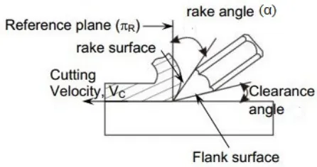
Rake Angle (α), the angle between the tool face and the plane normal to the surface of the cut through the tool cutting edge .Rake angle is a parameter used in various cutting and machining processes, describing the angle of the cutting face relative to the work. There are two rake angles, namely the back rake angle and side rake angle, both of which help to guide chip flow. Depending on the direction of the slope on the tool they are defined as positive, negative, and zero rake angles. … [1]
Figure (1): Rake angle of a single point cutting tool in action
[image:1.612.340.563.433.551.2]ISSN 2250-3153
resulting in higher temperatures yet it improves the surface finish. … [1]
A zero rake angle tool is the easiest to manufacture, but has tendency to a larger crater wear when compared to positive rake angle as the chip slides over the rake face. Recommended rake angles can vary depending on the material being cut, tool material, depth of cut, cutting speed, machine, and setup. Rake angles for drilling, milling, or sawing are often different. … [1]
Figure (2): Types of Rake angle on single point tool
B. Cutting ForceComponents:
In orthogonal cutting, the total cutting force (Fc) is conveniently resolved into two components in the horizontal and vertical direction, which can be directly measured using a force measuring device called a dynamometer. Also a small radial force will generate in zdirection which are shown in figure (3). … [1]
Figure (3): cutting components
II. WORK MATERIAL, CUTTING TOOL and
METHOD:
AISI 1018 steel has been used as the work piece material to conduct all the experiments. These type of materials are
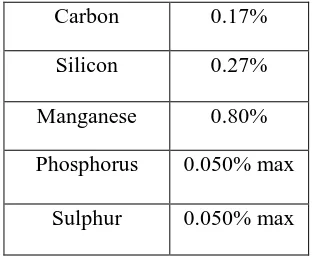
extensively used in the industrial applications. Samples were prepared from cylindrical bar with diameter of 25mm, prior to the experiments the specimens were turned with 1 mm cutting depth in order to remove the outer layer, which could appear discontinuous or unexpected hardening distribution due to theirextrusion production process. The chemical composition and mechanical properties of the selected work piece material are listed in table (1)
Table (1): Main Composition of AISI 1018 steel
Carbon 0.17%
Silicon 0.27%
Manganese 0.80%
Phosphorus 0.050% max
Sulphur 0.050% max
Table (2): Properties of AISI 1018 steel
Finish Bright Drawn
Yield Strength (MPa)
340-600
Tensile Strength (MPa)
430-750
Elongation % 12 min
Hardness (HB) 120-220
[image:2.612.35.296.200.320.2] [image:2.612.375.531.219.349.2] [image:2.612.362.547.396.540.2] [image:2.612.52.274.508.632.2]ISSN 2250-3153
Figure (4): Tool Geometry of single point cutting tool
Figure (5): Measurement of rake angle using profile projector
The various tool rake angles are: 0O, 5O, 10O, 17O, 18O, 20O, 25Oand a constant clearance angle was used. While turning a ductile material by a sharp tool, the continuous chip would flow over the tool’s rake surface and in the direction apparently perpendicular to the principal cutting edge. Practically, the chip may not flow along the orthogonal plane but this assumption is made for an ideal case.
The experiment were carried out by the use of lathe, dynamometer , and a couple of tools each having different rake angle ground on the rake face .The shear angle wasestimated by keeping the depth of cut (t) , feed (ƒ), and speed (N in RPM) constant and subsequently measuring chip thickness(tc). In order to measure the forces generated while machining, a dynamometer was used and the cutting force components were measured.
Here the side rake angle, end cutting angle, side cutting angle, end clearance angle, side clearance angle
arekept constant. The work piece for each experiment
would have the same diameter (25mm) and a constant machining length. The experimental setup is shown in figure (6) and figure (7);
Figure (6): Experimental setup
Figure (7): work piece and tool placed in setup along with dynamometre
III. RESULTS AND DISCUSSIONS
[image:3.612.52.278.54.435.2] [image:3.612.90.274.58.170.2] [image:3.612.327.585.142.284.2] [image:3.612.326.602.309.506.2]ISSN 2250-3153
Table no. (3): Comparison of experimental and
theoretical data
Here,
Shear angle is estimated using therelation,
Φ =Tan
-1(
𝟏𝟏−𝐫𝐫𝐫𝐫𝐫𝐫𝐫𝐫𝐫𝐫𝐫𝐫𝐫𝐫𝐫𝐫𝐫𝐫𝐫𝐫)
Where,
r is chip thickness ratio and α is rake angle
Variation of experimental cutting forces, Fy in particular with respect to rake angle is illustrated in the graph shown in figure (8);
Figure (8): graph showing variation of cutting force (Fc) with respect to rake angle
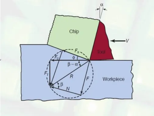
The theoretical approach to calculate cutting forces is given by merchant’sforce analysis. Pictorially the merchant’s circle is shown in figure 9…[5]
Figure (9): Merchant’s circle for Force Cutting Analysis
From the figure (8) it is evident that
𝑭𝑭
𝒄𝒄𝐫𝐫𝐫𝐫𝐫𝐫
(
𝜷𝜷 − 𝜶𝜶
) =
𝑭𝑭
𝒕𝒕𝐫𝐫𝐫𝐫𝐫𝐫
(
𝜷𝜷 − 𝜶𝜶
)
Therefore,
Fc= Ft cot(β-α)
010 20 30 40 50 60 70
0 5 10 15 20
cit
tin
g
for
ce
in
n
ew
ton
s
rake angle in degrees
[image:4.612.324.577.68.263.2] [image:4.612.31.267.187.360.2] [image:4.612.330.583.368.559.2]ISSN 2250-3153
Using the above equation the theoretical cutting force is calculated and the corresponding values are tabulated in table no (3) above. A comparison between theoretical cutting force and experimental cutting force is shown in
figure (9). Here the β value is assumed to be 45°.
IV. CONCLUSION
The cutting forces are also calculated using merchant’s force analysis and the values were compared with experimental results. From the table and graph it is observed that the theoretical and experimental results are in good agreement with a standard deviation of 5-10%, which may be attributed to the inherent variability of parameters of machining, materials,vibrations, atmosphere, and operator’s skill etc.
Further a decreasing pattern of cutting force initially up to an angle of18O is observed, beyond which there is an increase in cutting force. This could be due to increase in vibrations of the tool as the tool nose becomes weaker due to increase in positive rake angle.
V. ACKNOWLEDMENTS
We are thankful to the management of MUFFAKHAM JHA COLLEGE OF ENGINEERING AND TECHNOLOGY, Hyderabad and the technical staff for supporting this research work and preparation of specimens and testing etc.
VI. REFERENCES
1.
Effect of Rake Angles on Cutting Forces for ASingle Point Cutting Tool Pradeesh A. ; Mubeer M.; Nanda kishore; Muhammed Ansar ; Mohammed Manzoor T. ; Muhammed Raees M.
© 2016, IRJET, ISO 9001:2008 Certified Journal, Volume: 03 Issue: 05 | May-2016
2.
Lontos Experimental investigation of the effectof cutting depth, tool rake angle and workpiece material type on the main cutting force during a turning process. Proceedings of the 3rd International Conference on Manufacturing Engineering (ICMEN), 1-3 October 2008
3.
Mustafa Gunay, IhsanKorkut, ErsanAslan,UlviSekerExperimental investigation of the effect of cutting tool rake angle on main cutting force, Journal of Materials Processing Technology. 2005,166, 44–49.
4.
Tugrul O¨ zel ,Tsu-Kong Hsu, ErolZeren. Effectsof cutting edge geometry, workpiece hardness, feed rate and cutting speed on surface roughness and forces in finish turning of hardened AISI H13 steel, International Journal of Advanced Manufacturing Technology. 2005, 25, 262–269.
5.
HaciSaglam, FarukUnsacar, SuleymanYaldiz.Investigation of the effect of rake angle and approaching angle on main cutting force and tool tip temperature, International Journal of Machine Tools & Manufacture.2006, 46, 132– 14
6.
Effect of rake angles and material properties onchip formation Kundan Kumar Singh, Mayank joshi, Anurag Bahuguna, Rajesh Pant ISSN: 2319-5967 ISO 9001:2008 Certified International Journal of Engineering Science and Innovative Technology (IJESIT) Volume 3, Issue 6, November 2014