Iris Recognition for Personal Identification
MOHAMAD RAMLI, Nurul Akmar; KAMARUDIN, Muhammad Saufi and JORET, Ariffuddin Faculty of Electrical and Electronic Engineering
UNIVERSITI TUN HUSSEIN ONN MALAYSIA, Parit Raja, 86400, Batu Pahat, Johor, Malaysia
SUZUKI, Ichiro ICEE Conferences Secretariat
Mashiki, Ginowan City, Okinawa 123-4567, Japan
Abstract
A biometric system provides special and automatic identification of an individual based on characteristics and unique features showed by individuals. This paper examines the developing automated iris recognition for personal identification in order to verify both uniqueness of the human iris and also its performance as a biometric based on Hu invariant moment. The iris recognition system consists of the iris acquisition system and iris authentication algorithm. The algorithm of the processing for the iris recognition is also able to localize the pupil region and circular iris, occluding eyelashes and eyelids, and reflections. The system performed with a test on 108 images resulted on false accept rates (FAR) and false rejected rates (FRR). The performance measured which was stored in the database scored 0% each for FRR and FAR since the Hu invariance moments had matched perfectly. Therefore, iris recognition is shown to be an accurate and reliable biometric technology.
Keywords: Biometric, iris recognition, iris authentication algorithm, Hu invariance moments
1 INTRODUCTION
Biometrics’ system such as iris, fingerprint, signature and facial provides special and automatics identifications of an individual based on a characteristics and unique feature showed by individual. This paper examines automated iris recognition as a biometrically based technology for personal identification and verification. Iris recognition has received increasing attention due to its high reliability and accuracy. Most commercial iris recognition systems use patented algorithms developed by Cambridge researcher, John Daugman[1],[2]. These algorithms are able to produce perfect recognition rates.
As a physiological biometric, iris recognition aims to identify persons using iris characteristics of human eyes. Recently, iris recognition has received increasing attention due to its high reliability. Iris recognition combines pattern recognition, computer vision and statistics. It can serve as a living password that one need not to remember but always carries along. Iris recognition for personal identification is a system that can read an iris pattern and identify individual through the comparison with other template stored in
database
.
Iris recognition can be done by image processing.Image processing technique can be used to extract the iris pattern from a digitised image of the eyes. From the mathematical function, these biometrics templates can represent the unique information of an iris. This allows comparison to be made between templates. To use the iris recognition system, the subject eye is first photographed and then a template is created for their iris region. The template is then compares against all users in the system. If the template matching is found, the user is identified and access is granted. If no match is found, the subject remains unidentified.
In this paper, iris recognition algorithm using Hu invariant moment is proposed. To test the program, CASIA (Chinese Academy of Sciences Institute of Automation) iris database version 1.0 [3], which consist of 108 classes with 7 samples from each class, total of 756 images has been used but for this paper only one image from each class which total 108 images has been used. The histogram equalization, the filter and the Canny edge detection [4] were used in iris recognition process to compensate the partial unaccounted appearance in iris. Hu invariant moment is applied for recognize the iris. The iris recognition with 320x280 pixels were used as input data.
2
2. THE IRIS AUTHENTICATION ALGORITHMBefore iris performance can be done, iris
authentication algorithm must be performed. Figure 1.0
show the iris authentication algorithm composed of five systematic steps which are histogram equalization, filter, Canny edge detection, Hu moment and template matching.
Figure 1.0 : The Iris Authentication Algorithm
2.1 Histogram Equalization
Histogram equalization assigns the intensity values of pixels in the input image such that the output image contains a uniform distribution of intensities. It improves contrast and the goal of histogram equalization is to obtain a uniform histogram. This technique is used on a whole image.
Histogram equalization composed of three steps as following;
Step 1: The histogram formation regarding the brightness values of the original image. Step 2 : The new intensity calculation for each
intensity levels.
Step 3 : The previous intensity values is replaced with the new intensity values.
Equation (1) show the new intensity values are
calculated for each intensity level and Figure 2.0
demonstrate the iris image at before and after the histogram procedure
i i
N P I i h() max
(1)
h(i) : The new intensity value
Imax : The maximum intensity level (256)
Pi : Total number of pixel
Ni : The accumulation histogram of input image
(a) (b)
(c) (d)
Figure 2.0: The Histogram Equalization
Figure 2.0 (a) and(b) show the iris image and the
histogram obtained from the CASIA iris database while (c)
and(d) are the result generated by applying Equation (1)
2.2 The Filter
The filter is applied to eliminate the noise of the image. The filter also show the elimination of those iris image components which might generate possible errors in identifying the iris because of the unaccounted appearances such as eye lashes and eyelids.
(a) (b) Figure 3.0: The Process of Filter
Figure 3.0 (a) shows the histogram equalization image while (b) being filtered. As a result, Figure 3.0 (b)
which passed through the filter to rid of the eyelash and the eyelid is generally left.
2.3 The Canny Edge Detection
The edge of iris image takes an intensity image as its input, and returns a binary image of the same size as image, with 1's where the function finds edges in image and 0's elsewhere. The Canny method finds edges by looking for local maxima of the gradient of the iris image. The Canny edge detects strong and weak edges, and includes the weak edges in the output only if they are connected to strong edges. This method is therefore less likely than the others to be fooled by noise, and more likely to detect true weak edges.
(a) (b)
Figure 4.0: The Procedures of Canny Edges Detection
Figure 4.0 shows the iris image by considering the Canny edge detection. The Figure 4.0 shows the original iris image Figure 4.0 (a) before it used Canny edge detection while the iris image (b) is the result after passed through the edge detection.
2.4 The Invariant Moment
Equation (2) show the discrete version of the Cartesian moment for an iris image consisting of pixels P(x,y) while the equation (3) define as the total mass of the
image where m00is the zero order moment. For the center of
mass are given by equation (4) and (5). Two dimensional centralized moment is given by equation (6).
Iris Recognition for Personal Identification
MOHAMAD RAMLI, Nurul Akmar; KAMARUDIN, Muhammad Saufi and JORET, Ariffuddin Faculty of Electrical and Electronic Engineering
UNIVERSITI TUN HUSSEIN ONN MALAYSIA, Parit Raja, 86400, Batu Pahat, Johor, Malaysia
SUZUKI, Ichiro ICEE Conferences Secretariat
Mashiki, Ginowan City, Okinawa 123-4567, Japan
Abstract
A biometric system provides special and automatic identification of an individual based on characteristics and unique features showed by individuals. This paper examines the developing automated iris recognition for personal identification in order to verify both uniqueness of the human iris and also its performance as a biometric based on Hu invariant moment. The iris recognition system consists of the iris acquisition system and iris authentication algorithm. The algorithm of the processing for the iris recognition is also able to localize the pupil region and circular iris, occluding eyelashes and eyelids, and reflections. The system performed with a test on 108 images resulted on false accept rates (FAR) and false rejected rates (FRR). The performance measured which was stored in the database scored 0% each for FRR and FAR since the Hu invariance moments had matched perfectly. Therefore, iris recognition is shown to be an accurate and reliable biometric technology.
Keywords: Biometric, iris recognition, iris authentication algorithm, Hu invariance moments
1 INTRODUCTION
Biometrics’ system such as iris, fingerprint, signature and facial provides special and automatics identifications of an individual based on a characteristics and unique feature showed by individual. This paper examines automated iris recognition as a biometrically based technology for personal identification and verification. Iris recognition has received increasing attention due to its high reliability and accuracy. Most commercial iris recognition systems use patented algorithms developed by Cambridge researcher, John Daugman[1],[2]. These algorithms are able to produce perfect recognition rates.
As a physiological biometric, iris recognition aims to identify persons using iris characteristics of human eyes. Recently, iris recognition has received increasing attention due to its high reliability. Iris recognition combines pattern recognition, computer vision and statistics. It can serve as a living password that one need not to remember but always carries along. Iris recognition for personal identification is a system that can read an iris pattern and identify individual through the comparison with other template stored in
database
.
Iris recognition can be done by image processing.Image processing technique can be used to extract the iris pattern from a digitised image of the eyes. From the mathematical function, these biometrics templates can represent the unique information of an iris. This allows comparison to be made between templates. To use the iris recognition system, the subject eye is first photographed and then a template is created for their iris region. The template is then compares against all users in the system. If the template matching is found, the user is identified and access is granted. If no match is found, the subject remains unidentified.
In this paper, iris recognition algorithm using Hu invariant moment is proposed. To test the program, CASIA (Chinese Academy of Sciences Institute of Automation) iris database version 1.0 [3], which consist of 108 classes with 7 samples from each class, total of 756 images has been used but for this paper only one image from each class which total 108 images has been used. The histogram equalization, the filter and the Canny edge detection [4] were used in iris recognition process to compensate the partial unaccounted appearance in iris. Hu invariant moment is applied for recognize the iris. The iris recognition with 320x280 pixels were used as input data.
2. THE IRIS AUTHENTICATION ALGORITHM
Before iris performance can be done, iris
authentication algorithm must be performed. Figure 1.0
show the iris authentication algorithm composed of five systematic steps which are histogram equalization, filter, Canny edge detection, Hu moment and template matching.
Figure 1.0 : The Iris Authentication Algorithm
2.1 Histogram Equalization
Histogram equalization assigns the intensity values of pixels in the input image such that the output image contains a uniform distribution of intensities. It improves contrast and the goal of histogram equalization is to obtain a uniform histogram. This technique is used on a whole image.
Histogram equalization composed of three steps as following;
Step 1: The histogram formation regarding the brightness values of the original image. Step 2 : The new intensity calculation for each
intensity levels.
Step 3 : The previous intensity values is replaced with the new intensity values.
Equation (1) show the new intensity values are
calculated for each intensity level and Figure 2.0
demonstrate the iris image at before and after the histogram procedure
i i
N P I i h() max
(1)
h(i) : The new intensity value
Imax : The maximum intensity level (256)
Pi : Total number of pixel
Ni : The accumulation histogram of input image
(a) (b)
(c) (d)
Figure 2.0: The Histogram Equalization
Figure 2.0 (a) and(b) show the iris image and the
histogram obtained from the CASIA iris database while (c)
and(d) are the result generated by applying Equation (1)
2.2 The Filter
The filter is applied to eliminate the noise of the image. The filter also show the elimination of those iris image components which might generate possible errors in identifying the iris because of the unaccounted appearances such as eye lashes and eyelids.
(a) (b) Figure 3.0: The Process of Filter
Figure 3.0 (a) shows the histogram equalization image while (b) being filtered. As a result, Figure 3.0 (b)
which passed through the filter to rid of the eyelash and the eyelid is generally left.
2.3 The Canny Edge Detection
The edge of iris image takes an intensity image as its input, and returns a binary image of the same size as image, with 1's where the function finds edges in image and 0's elsewhere. The Canny method finds edges by looking for local maxima of the gradient of the iris image. The Canny edge detects strong and weak edges, and includes the weak edges in the output only if they are connected to strong edges. This method is therefore less likely than the others to be fooled by noise, and more likely to detect true weak edges.
(a) (b)
Figure 4.0: The Procedures of Canny Edges Detection
Figure 4.0 shows the iris image by considering the Canny edge detection. The Figure 4.0 shows the original iris image Figure 4.0 (a) before it used Canny edge detection while the iris image (b) is the result after passed through the edge detection.
2.4 The Invariant Moment
Equation (2) show the discrete version of the Cartesian moment for an iris image consisting of pixels P(x,y) while the equation (3) define as the total mass of the
image where m00is the zero order moment. For the center of
¦¦
M x N y xy q p pq x y P m1 1 (2)
¦¦
M x N y xy P m 1 1 00 (3) 00 10 m m x (4) 00 01 m m y (5)¦¦
M x N y xy q ppq x x y y P
n
1 1 (6)
The definition of central moment can be defined as below, as defined in [6]:
20
n = The abscissa variance
02
n = The ordinate variance
11
n = Covariance of ordinate and abscissa
12
n = Distribution intensity towards the right side compared
to the left side of abscissa
21
n = Distribution intensity towards the upper side compared
to the lower side in ordinate 30
n = The abscissa skew intensity
03
n = The ordinate skew intensity
The normalization moment divides the central moment into a certain size of values and this sizing grants the invariant characteristic [26] as shown in equation (7).
oo s
pq
pq n
n
u where 1
2
q p s
(7)
In this paper, Hu invariance moment [13] was extracted by applying equation (7). It was used for the iris recognition algorithm. Hu invariance moment is constituted of level 2 and 3 central moment as demonstrated in equation (8).
02 20
1 u u
I 11 2 2 02 20
2 (u u ) 4u
I 2 03 21 2 12 30
3 (u 3u ) (3n n )
I 2 03 21 2 12 30
4 (u u ) (n n )
I (8)
] ) ( ) ( 3 [ ) )( 3 ( } ) ( 3 ) )[( )( 3 ( 2 30 21 2 12 30 03 21 03 21 2 03 21 2 12 30 12 30 12 30 5 u u u u u u n n u u u u u u u u I )] )( ( 4 ) ( ) )[(
( 20 02 30 12 2 21 03 2 11 30 12 21 03
6 u u u u u u u u u u u
I ] ) ( ) ( 3 [ ) )( 3 ( ] ) ( 3 ) )[( )( 3 ( 2 03 21 2 12 30 03 21 12 30 2 03 21 2 12 30 12 30 03 21 7 u u u u u u u u u u u u u u u u I
Hu moment defined in equation (8) can be explained as followings, according to [6];
1
I
= The sum of horizontal and vertical directed variance, more distributed towards horizontal and vertical axes and the values are enlarged.2
I
= The co-variance value of vertical and horizontal axes when the variance intensity of vertical axis and horizontal axis is similar.3
I
= The result emphasizing the values inclined to left or right and upper or lower axes.4
I
= The result emphasizing the values counterbalancing toleft or right and upper or lower axes.
5
I
,I
6,I
7= The extraction of values invariant against size, rotation and location.2.5 Template Matching
The template matching was generally based on the minimum error calculation. This is an algorithm searching for the data which it is distance value between the Hu invariance moments of the iris image is below the certain value for Hu invariance moment embedded within the database and authentication. The most minimum error from the database when the author compared with the original iris is belongs to the right subject. From the minimum error calculation, the process of identification process can be performed.
3. EXPERIMENT AND RESULTS
3.1 Iris Recognition Database
The performance of proposed algorithm was measured by using the Chinese Academy of Sciences (CASIA) iris database. This is composed of images of 108 different eyes but the author only used 100 samples where 8 more samples defined as not recognized. These images are 320x280 8-bit bitmapped imaged (.bmp).
3.2 Iris Performance
From five steps above, the iris performance can be performed and seen. The matching sequence of the Hu invariance moments stored in iris database and those moments of input iris was selected as the iris recognition technique. The input iris was authenticated as the valid iris if the distance between the stored and input was below the certain value.
The performance measurement of the iris recognition algorithm based on the 100 samples scored 0% each for FRR and FAR since the Hu invariance moments had matched perfectly. In this paper, the iris recognition was executed with the iris data collected from the iris recognition software stored in the database and the iris image. Therefore, those irises with any changes occurring in the iris image were the input to the data.
The experiment has been done to test the program. By using 100 samples of user iris image, the test has confirmed the successful of the author program. By using template matching, each time the tested user iris image does
4
fit the data; it will contribute a success to the author’s program. After 100 of experiment have been done, the author has achieved 100% of success of the author program. Test result shows that iris recognition is the most reliable and secured biometric recognition
3.3 Identification
At this procedure, main program compare the taken picture with the database to verify. To test the program, CASIA (Chinese Academy of Sciences Institute of Automation) iris database version 1.0, which consists of 108 iris images have been used. The entire iris image deputizes by unique number from 1 until 108. To test the program only 100 samples of iris image will know as recognize user and stored in the database while another 8 samples of iris image will be categorized as unknown user.
For the categorized of recognize user, the program will verified the iris image and it will sent a command to give access and identify the user. For this project if the recognition of iris is successful, it will show the number of subject and the message box that show the user has been recognized. Figure 5.0 show the recognition result for the recognized user.
[image:3.595.110.287.84.225.2]Figure 5.0: Recognition Result for User Iris Image No. 23
Figure 5.0 showed the recognized iris image. The author assumed the sample of iris image as an entered user iris image. After the author pressed the ‘run’ button, the program start calculated the iris image, compared the image with the database and recognized the image by showing the correct number of subject.
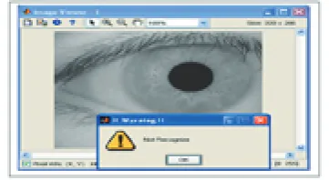
Figure 6.0: Recognition Result for Unknown User Iris Image
The author also tested the program for an unrecognized user by using 8 samples of iris image. The author assumed the 8 sample of iris image as an unrecognized user by not stored their iris data into the database. When the author entered the unknown iris image and pressed the ‘run’ button, the program cannot identify the image. If access is not granted by the main program it send a command to the program and the program will prompt user to ‘Warning-Not Recognized’ through the MATLAB
command. Figure 6.0 show the result of unknown user.
3.4 Iris Recognition Rate
The iris recognition system proposed in this paper was running in Matlab 7.0 and the computer specification used for this experiments was Intel Celeron with processors 1.5 GHz powered by 760 MB RAM. The time needed for iris recognition was approximately 3 seconds. The searching period tended to change with respect to the amount of database. There were total 100 numbers of irises stored in the database for this experiment.
4.0 CONCLUSIONS
This paper has presented iris recognition for personal identification system, which was tested using the database of greyscale eye images in order to verify the claimed performance of iris recognition technology.
An automatic segmentation algorithm was presented, which would localise the iris region from an eye image and isolate eyelid, eyelash and reflection areas by using moment invariant technique. Automatic segmentation was achieved through the use of the canny edge detector for localising the iris and pupil regions while was also employed to perform the segmentation on the basis different intensities of an image.
Matching is a final part in the iris recognition system. On matching part, it consist a template matching which used False Acceptance Rate (FAR) and False Rejection Rate (FRR) technique to match the user iris image with the database.
In this report, FAR and FRR are calculated after acquiring 100 images from 108 users. The results presented have shown that segmentation can be the most difficult stage of iris recognition because its success is dependent on the imaging quality of eye images. After removing undesired area the successful rate increased up to 100 %.
¦¦
M x N y xy q p pq x y P m1 1 (2)
¦¦
M x N y xy P m 1 1 00 (3) 00 10 m m x (4) 00 01 m m y (5)¦¦
M x N y xy q ppq x x y y P
n
1 1 (6)
The definition of central moment can be defined as below, as defined in [6]:
20
n = The abscissa variance
02
n = The ordinate variance
11
n = Covariance of ordinate and abscissa
12
n = Distribution intensity towards the right side compared
to the left side of abscissa
21
n = Distribution intensity towards the upper side compared
to the lower side in ordinate 30
n = The abscissa skew intensity
03
n = The ordinate skew intensity
The normalization moment divides the central moment into a certain size of values and this sizing grants the invariant characteristic [26] as shown in equation (7).
oo s
pq
pq n
n
u where 1
2
q p s
(7)
In this paper, Hu invariance moment [13] was extracted by applying equation (7). It was used for the iris recognition algorithm. Hu invariance moment is constituted of level 2 and 3 central moment as demonstrated in equation (8).
02 20
1 u u
I 11 2 2 02 20
2 (u u ) 4u
I 2 03 21 2 12 30
3 (u 3u ) (3n n )
I 2 03 21 2 12 30
4 (u u ) (n n )
I (8)
] ) ( ) ( 3 [ ) )( 3 ( } ) ( 3 ) )[( )( 3 ( 2 30 21 2 12 30 03 21 03 21 2 03 21 2 12 30 12 30 12 30 5 u u u u u u n n u u u u u u u u I )] )( ( 4 ) ( ) )[(
( 20 02 30 12 2 21 03 2 11 30 12 21 03
6 u u u u u u u u u u u
I ] ) ( ) ( 3 [ ) )( 3 ( ] ) ( 3 ) )[( )( 3 ( 2 03 21 2 12 30 03 21 12 30 2 03 21 2 12 30 12 30 03 21 7 u u u u u u u u u u u u u u u u I
Hu moment defined in equation (8) can be explained as followings, according to [6];
1
I
= The sum of horizontal and vertical directed variance, more distributed towards horizontal and vertical axes and the values are enlarged.2
I
= The co-variance value of vertical and horizontal axes when the variance intensity of vertical axis and horizontal axis is similar.3
I
= The result emphasizing the values inclined to left or right and upper or lower axes.4
I
= The result emphasizing the values counterbalancing toleft or right and upper or lower axes.
5
I
,I
6,I
7= The extraction of values invariant against size, rotation and location.2.5 Template Matching
The template matching was generally based on the minimum error calculation. This is an algorithm searching for the data which it is distance value between the Hu invariance moments of the iris image is below the certain value for Hu invariance moment embedded within the database and authentication. The most minimum error from the database when the author compared with the original iris is belongs to the right subject. From the minimum error calculation, the process of identification process can be performed.
3. EXPERIMENT AND RESULTS
3.1 Iris Recognition Database
The performance of proposed algorithm was measured by using the Chinese Academy of Sciences (CASIA) iris database. This is composed of images of 108 different eyes but the author only used 100 samples where 8 more samples defined as not recognized. These images are 320x280 8-bit bitmapped imaged (.bmp).
3.2 Iris Performance
From five steps above, the iris performance can be performed and seen. The matching sequence of the Hu invariance moments stored in iris database and those moments of input iris was selected as the iris recognition technique. The input iris was authenticated as the valid iris if the distance between the stored and input was below the certain value.
The performance measurement of the iris recognition algorithm based on the 100 samples scored 0% each for FRR and FAR since the Hu invariance moments had matched perfectly. In this paper, the iris recognition was executed with the iris data collected from the iris recognition software stored in the database and the iris image. Therefore, those irises with any changes occurring in the iris image were the input to the data.
The experiment has been done to test the program. By using 100 samples of user iris image, the test has confirmed the successful of the author program. By using template matching, each time the tested user iris image does
fit the data; it will contribute a success to the author’s program. After 100 of experiment have been done, the author has achieved 100% of success of the author program. Test result shows that iris recognition is the most reliable and secured biometric recognition
3.3 Identification
At this procedure, main program compare the taken picture with the database to verify. To test the program, CASIA (Chinese Academy of Sciences Institute of Automation) iris database version 1.0, which consists of 108 iris images have been used. The entire iris image deputizes by unique number from 1 until 108. To test the program only 100 samples of iris image will know as recognize user and stored in the database while another 8 samples of iris image will be categorized as unknown user.
For the categorized of recognize user, the program will verified the iris image and it will sent a command to give access and identify the user. For this project if the recognition of iris is successful, it will show the number of subject and the message box that show the user has been recognized. Figure 5.0 show the recognition result for the recognized user.
[image:4.595.71.274.356.451.2]Figure 5.0: Recognition Result for User Iris Image No. 23
[image:4.595.82.263.555.654.2]Figure 5.0 showed the recognized iris image. The author assumed the sample of iris image as an entered user iris image. After the author pressed the ‘run’ button, the program start calculated the iris image, compared the image with the database and recognized the image by showing the correct number of subject.
Figure 6.0: Recognition Result for Unknown User Iris Image
The author also tested the program for an unrecognized user by using 8 samples of iris image. The author assumed the 8 sample of iris image as an unrecognized user by not stored their iris data into the database. When the author entered the unknown iris image and pressed the ‘run’ button, the program cannot identify the image. If access is not granted by the main program it send a command to the program and the program will prompt user to ‘Warning-Not Recognized’ through the MATLAB
command. Figure 6.0 show the result of unknown user.
3.4 Iris Recognition Rate
The iris recognition system proposed in this paper was running in Matlab 7.0 and the computer specification used for this experiments was Intel Celeron with processors 1.5 GHz powered by 760 MB RAM. The time needed for iris recognition was approximately 3 seconds. The searching period tended to change with respect to the amount of database. There were total 100 numbers of irises stored in the database for this experiment.
4.0 CONCLUSIONS
This paper has presented iris recognition for personal identification system, which was tested using the database of greyscale eye images in order to verify the claimed performance of iris recognition technology.
An automatic segmentation algorithm was presented, which would localise the iris region from an eye image and isolate eyelid, eyelash and reflection areas by using moment invariant technique. Automatic segmentation was achieved through the use of the canny edge detector for localising the iris and pupil regions while was also employed to perform the segmentation on the basis different intensities of an image.
Matching is a final part in the iris recognition system. On matching part, it consist a template matching which used False Acceptance Rate (FAR) and False Rejection Rate (FRR) technique to match the user iris image with the database.
In this report, FAR and FRR are calculated after acquiring 100 images from 108 users. The results presented have shown that segmentation can be the most difficult stage of iris recognition because its success is dependent on the imaging quality of eye images. After removing undesired area the successful rate increased up to 100 %.
5
5.0 REFERENCES[1] J. Daugman.(2002) “How iris recognition works. Proceedings of 2002 International Conference on Image Processing”, Vol. 1.
[2] J. Daugman.(1994) Biometric personal identification system based on iris analysis. United States Patent, Patent Number: 5,291,560.
[3] Chinese Academy of Sciences – Institute of
Automation(2003). Database of 756 Greyscale Eye
Images. http://www.sinobiometrics.com Version 1.0. [4] Canny Edge Detection
www.mathworks.com/access/helpdesk/help/toolbox/ima ges/edge.html
[5] Libor Masek, Peter Kovesi.(2003) “MATLAB Source Code for a Biometric Identification System Based on Iris Patterns.” The School of Computer Science and Software Engineering, The University of Western Australia.
[6] Noh J.S, RHEE K.H (2005) “Palmprint Identification Algorithm using Hu Invariant Moments and Otsu
Binarization”. Proceedings of the Fourth Annual ACIS
International Conference on Computer and Information Sciences (ICIS’ 05)
6.0 BIOGRAPHIES
Muhammad Saufi Kamarudin obtained his B. Eng. degree in Electrical Engineering and M. Eng. from Universiti Teknologi Malaysia in 2003 and 2005, respectively. Currently he is a lecturer and researcher in Universiti Tun Hussein Onn Malaysia. His interest areas are high voltage engineering and power systems.
Ariffuddin Joret obtained his B. Eng. degree in Electrical & Electronic Engineering and M. Eng. from Universiti Kebangsaan Malaysia in 2003 and 2006, respectively. Currently he is a lecturer and researcher in Universiti Tun Hussein Onn Malaysia. His interest areas are digital communication and computer engineering.