Capacity Based Multicast Channel Assignment in Wireless
Mesh Network
Anju Singh*, Karan Singh, Sandeep Sharma
School of Information and Communication Technology, Gautam Buddha University, Greater Noida, India Email: *[email protected], [email protected], [email protected]
Received May 2013
ABSTRACT
Wireless mesh networking (WMN) is an emerging technology that enables multihop wireless connectivity to areas where wiring or installing cables is difficult or expensive. Multicast is a form of communication that delivers informa-tion from a source to a group of destinainforma-tions. In a single-channel WMN, all nodes share and communicate with each other via the same channel. In such a network, the throughput capacity of multicast degrades significantly as the net-work size increases. A critical factor that contributes to this rapid degradation is the co-channel interference in sin-gle-channel WMNs. The major advantage of WMN is that power is not the major issue as compare to other wireless network like MANET, Sensor etc. Hence Power can be optimally utilized in WMN to increase throughput and total network efficiency. In this paper, we propose a channel assignment algorithm for multicast based on high channel ca-pacity with minimum interference. This scheme uses all overlapping and non overlapping channel for the channel as-signment. By this scheme we provide better performance in terms of average packet delivery ratio, average throughput and average end to end delay with respect to multichannel multicast channel assignment schemes.
Keywords: WMN; Multicast; Multi Interface; Non Overlapping Channels; Partially Overlapping Channels; SNR
1. Introduction
Wireless mesh network is also known as community wireless networks. It is an emerging technology that sup-ports many important applications such as Internet access provisioning in rural areas, ad hoc networking for emer-gency and disaster recovery, security surveillance, and information services in public transportation systems. Due to its promising technology it is becoming the major ave-nue for the next generation of wireless mobility [7]. The technology enables networking capability where wiring or installing cables are difficult or expensive. Wireless mesh network (WMN) is a new cost effective technology which constructs a resilient, locally networked access to communication infrastructure. This is due to its desirable characteristics multi-hop routing, auto configuration, band-width fairness, low cost, easy deployment, self healing and self organized.
In the recent years, the demand for multicast TV, vid-eo conference and online multicast based games are huge-ly increased. More online programs that could be live soccer match or live performance made the multicast communication more important research topic in WMNs [8]. Some commercial deployments are already working
to provide low-cost connectivity to residents and local businesses. Multicast is a form of communication that delivers information from a source to a group of destina-tions simultaneously in an efficient manner. Important applications of multicast include distribution of financial data, billing records, software, and newspapers; audio/ video conferencing; distance education; IP television; and distributed interactive games. Research on multicast in WMNs has considered mostly networks with a single channel, i.e., all nodes in the network share and commu-nicate with each other via one single channel [4]. The study shows that the throughput capacity of a single- channel WMN degrades significantly as the network size increases.
Traditionally, WMN were equipped with node having a single radio. They were faced with number of limita-tions such as lower throughput and limited use of availa-ble wireless channels [5]. Major issue of wireless net-work is its deployment so WMN are preferred over other wireless network due to its random assignment node and capacity enhanced feature. But, using single channel creates interference like hidden terminal problem and exposed terminal problem. So, this problem can be improved by using multi channel in wireless mesh network.
Multiple channels with multi radio are one of the most
effective approaches to achieve higher throughput. The network throughput in these multichannel systems can be increased multiplicatively at the cost of additional inter-face equipment. The tremendous popularity of wireless networking in recent years has led to the commoditiza-tion of wireless radios whose prices have fallen dramati-cally thanks to technology advances and mass production [6]. Therefore, the idea of multi-interface multi-channel wireless networking is very promising, allowing us to use two or more radios on the same device. The network has n channels, which may either overlap, such that a channel partially shares its frequency spectrum with the adjacent channels, or may be completely separated (non-overlap- ping or orthogonal). Orthogonal channels do not interfere with each other.
This paper focuses on the channel allocation scheme which efficiently utilizes multiple wireless interfaces to achieve better throughput thereby increasing the network capacity. We are using the capacity based channel as-signment in which channel are assigned on the basis of the link which has high capacity and have some channel difference to already assigned channel. On average, a mul-tichannel wireless network at least doubles the through-put, since each node is now in full-duplex mode, being able to transmit and receive simultaneously. Multi-in- terface networks, in return, require efficient channel as-signment (CA) and routing algorithms that can take ad-vantage of multiple channels and multiple interfaces.
2. Related Work
Guokai etal. [1] proposed the channel assignment scheme through Ascending and Heuristic approach. In which in-itially construct the multicast tree using level channel as-signment (LCM) and multichannel multicast (MCM) ap-proach then assign the channels to it. Mesh network in-itially needs to convert in a spanning structure and Tree structure is the least complex structure. So by LCA and MCM form the tree. Level Channel Assignment (LCA) is a method to build a multicast tree. Initially, the nodes obtain their level information [2]. The BFS is used to traverse the whole network. All the nodes are portioned into different levels according to the hop count distances between the source and the nodes. If node a (in level i) and b (in level i + 1) are within each other “s” communi-cation range, then “a” is called the parent of “b”, and “b” is called the child of “a”. Then build a multicast tree based on the node level information. Initially, the source and all the receivers are included in the tree.
Then, for each multireceiver v, if one of its parents is a tree node then connect it with that parent, and stop. Oth-erwise randomly choose one of its parents, say fv, as relay node on the tree, and connect v and fv. Afterwards, we try to find out the relay node for fv recursively. The
process repeats until the entire multireceiver is included in the multicast tree.
The tree nodes decide their channel assignment with the level information.
• The source node (level 0) only uses one interface, which is assigned channel 0. This interface is respon-sible for sending packets to the tree nodes in level 1. • The internal tree node in level i (i ≥ 1) uses two
inter-faces: one is assigned channel i − 1, which is used to receive packets from the upper level; the other is as-signed channel 1, which is used to forward the pack-ets to the tree nodes at level i + 1.
• The leaf in the level i (i ≥ 1) uses two interfaces: one uses channel i − 1 to receive the packets from level i − 1, the other uses channel i to forward the packets to the mesh clients within the communication range that desire to receive the packets.
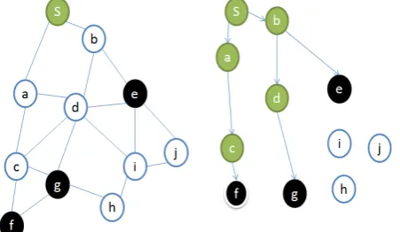
For example in Figure 1, the node s is the source and nodes f, g, e are the multireceiver. In Figure 1 {s, f, g, and e} are included in the multicast tree. Since nodes of g’s parents are tree nodes, it randomly selects d as a par-ent node and connects node g with d. Then choose d’s parent b as a tree node and connect d with b. Since b’s parent s is a tree node connect b with s. Next, we start from multireceiver e. Connect e with its parent node b and stop because b is already connected with tree node s. Similarly the third multireceiver f, connect f with c, c with a and then a with s. Thus the tree construction is completed by connecting all the receivers with the tree.
Multichannel Multicast (MCM) is another approach to construct multicast tree in which the throughput increases effectively [3]. Here the main aim is to minimize the number of relay nodes and hop count distance between source and destination. When all the Nodes are multire-ceiver, the multicast problem becomes the broadcast prob-lem. Broadcast is a special case of multicast. The broad-cast structure in the mesh network is built by the follow-ing steps:
• After the BFS traversal, all the nodes are divided into different levels.
[image:2.595.314.540.583.714.2]
• Delete the edges between any two nodes of the same level, with which we get the elementary communica-tion structure “tree mesh”.
• Identify the minimal number of relay nodes that form the broadcast tree.
Using more relay node means more transmissions in the network. Because the number of available channel is limited, more transmissions would result in more inter-ference and result in more bandwidth cost. Hence, mini-mizing the multicast tree size helps to improve the throughput. The purpose of this step is to identify the relay node for a node that has more than one parent nodes so that the number of relay node is minimal. In broadcast structure unnecessary branches are present if the destinations do not involve all the nodes. Hence, we propose to construct a structure using the MCM Tree Construction algorithm. The goal of the algorithm is to discover the minimal number of relay nodes needed to construct a multicast tree. The search process starts from the bottom to the top.
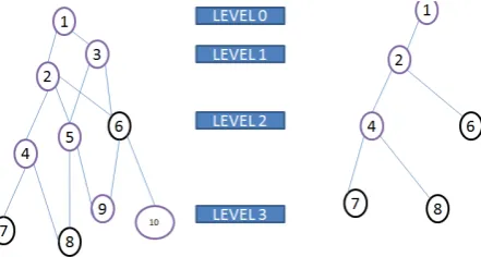
A simple example is shown to explain the process in a tree mesh in Figure 2, where nodes 6, 7, and 8 are the multireceiver. First select node 4 at level 2 because it covers all the multireceiver at level 3. Next select node 2 at level 1, which covers all the multi receivers and the relay node at level 2. By doing these steps finally we get the multicast tree in Figure 2 because it covers all the multireceiver at level 3. Next select node 2 at level 1, which covers all the multi receivers and the relay node at level 2. By doing these steps finally we get the multicast tree in Figure 2.
[image:3.595.65.286.600.718.2]Ascending Approach: In ascending approach from top to down in the tree, the channels are assigned to the Interfaces in the ascending order until the maximum chan-nel Number is reached, then start from chanchan-nel 0 again. Each child node of a parent gets the same channel alloca-tion. This approach avoids the situation that the same Channel is assigned to two nearby links that interfere with each other. The number above the node represents the channel number used for its RI, while the number below the node represents the channel number for its SI. In the algorithm, only the limited orthogonal Channels
Figure 2. Multichannel multicast tree construction.
are used. 802:11b provides 11 channels in American do-main which are 5 MHz apart in frequency. To be totally orthogonal, the frequency should be at least 30 MHz, so 802:11b can offer only three non-overlapping channels. Thus, although the Ascending Channel Allocation is easy to implement, its performance is still constrained by the limited number of orthogonal channels.
Heuristic Approach: In this, utilize all the channels available in band. Interference range decreases with chan-nel separation. If physical distance is short b/w two wire-less links then channel separation should be large. Here, main objective is to minimize the sum of interference area of all transmission. Bigger interference area means bigger chance two transmissions may interfere. When al-locating a channel for relay node u, the channel assign-ment should take a channel that minimizes the sum of the square of the IRs between u and us neighbouring relay nodes, that is, minimize IR 2(uv) where N(u) represents the set of the neighbouring relay nodes of u. This is be-cause the bigger interference area means the bigger chance two transmissions may interfere.
3. Proposed Work
The existing schemes of channel assignment in WMN used the non overlapping channels only and provide im-provement in system performance characteristics like throughput, delay but wasted the limited resource. In the proposed work we will show the use of all available channels.
3.1. System Model
We model a WMN as a graph G (V, E), with nodes V and links E. Assume T ⊆ V is the set of gateways. Each gateway has a high-bandwidth connection to the Internet, and can be viewed as a data source. Let S be the set of data transmission sessions. We define five vectors of variables. The first four are: the vector of data flows f; the vector of multicast throughput r; the vector of link capacities c; and the power assignment vector P. The last one is on channel assignment. We assume that each node is equipped with radio of capacity c. Here Γ represents the set of pre-defined channels in the IEEE 802.11b/g standard.
near about 3 channels amongst 11 available channels of IEEE 802.11 standards are used. But, in our proposed scheme for each transmission we use one of the 11 nels of IEEE 802.11 standard. Now we proposed a chan-nel scheme that is based on chanchan-nel capacity and chanchan-nel separation both. We know that channel correlation coef-ficient is inversely proportional to channel separation and channel interference is directly related to channel corre-lation coefficient. We analyse that if channel capacity is high then it can tolerate some amount of interference. We find that channel capacity not only depends upon the channel separation but also depends on some other fac-tors. So, channel capacity of channel defined by the fol-lowing equation
Where b bandwidth, Gee = Gain, Pe = Power of chan-nel e, Ile = Chanchan-nel correlation coefficient, Pl = power of channel l, Gle = Interference coefficient between channel e and l, σ2 = Noise associated with a link.
C = blog2 (1 + SINRe) (1) Where,
ee e e
1e 1 1e 2 1 e
G P SINR
I P G σ ≠
=
+
∑
(2)So, we observe that my proposed work which is based on channel capacity show that when channel capacity is high, it can tolerate up to a threshold limit of channel interference factor.
3.2. Procedure for Channel Assignment
We are providing the procedure of proposed work in fol-lowing way:
STEP 1 Create mesh network with the help of adja-cencymatrix. Setstackofallchannels.
STEP 2Giventotalno. ofchannelsC thatisdefined inIEEE 802.11 standards.
STEP 3 Now set the parameter for all channels, ac-cordingtoequationnumber 1.
STEP 4UseBFS algorithmfortraversingnodefrom sourcenodetoalldestinationnodes.
STEP 5AssignanychanneltosourcenodeS.
STEP 6 Now, calculatethecurrentlinkcapacityusing Equation (1) for next all intermediate nodes between sourcetoalldestinationandcalculatethechannel sepa-rationbetweenassumedandalreadyusedchannel.
STEP 7Checktheassignmentrequirement:
1) If calculated channel capacity is more than thre-sholdcapacity.
2) Ifchannelseparationismorethanthreshold.
STEP 8 Select channel e for which Ce is maximum andchannelseparationismore.
STEP 9 AssignthatchannelCetocurrentNode.
STEP 10Repeatthesesteps 4 to 8 untilallstacksare empty.
4. Result Analysis
4.1. Simulation Environment
The proposed work is simulated in QualNet in which a simulation environment is created for demonstrating the channel Assignment schemes for wireless mesh network.
4.2. Performance Matrices
Packet delivery, throughput and delay are major perfor-mance criteria for channel assignment schemes for wire-less mesh network.
4.3. Simulation Parameters
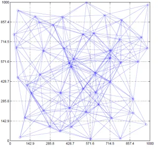
We simulated a small network of 50 nodes uniformly distributed over a 1000 m × 1000 m area shown in Fig-ure 3. The transmission power and transmission range of each node were varying. We adapt the uniform distribu-tion to distribute loads evenly and to minimize interfe-rence among routers. The number of nodes and the cor-responding network size were chosen in such a way that there were no disjoint nodes or network partitions through-out the simulation. The uniform distribution of nodes, the network size was computed such that any one-hop neigh-boring nodes were within the transmission range of each other. We used the IEEE 802.11b standard at the physical layer with a transmission rate of 11 Mbits/s. The IEEE 802.11 Carrier Sense Multiple Access with Collision Avoidance (CS-MA/CA) is chosen as the medium access control (MAC) for multicast transmissions.
Each multicast group has one source. The source of a multicast group transmits at a constant bit rate properly set for each experiment. The numbers of multicast desti-nations (the group size) are also specified for each scena-rio. The source and the destinations of a multicast group were selected randomly. All destinations joined a multi-cast group at the beginning and stayed until the whole group terminated. In each experiment, the source sent data for 300 seconds of simulated time, at a constant bit rate specified for each experiment. After the source fi-nished sending, the simulation continued to run for 100 seconds of simulated time to give the last packets time to be processed and routed, for a total of 400 seconds. This 400-second duration does not include the time needed for constructing the routing tree at the beginning.
4.4. Experiment Scenario
We measured the average packet delivery ratio, end to end delay and throughput as functions of Multicast Source Rate, Multicast Group Size, Number of Channels
Figure 3. Network topology.
The number of multicast destinations in the multicast group ranged from 1 to 30 nodes in the 50-node network. The multicast source rates were set at 60 packets/s and 40 packets/s in the small and medium-size networks, respectively. Number of channels: The total number of overlapping and non-overlapping channels was varied from 1 to 20. In the small network of 50 nodes, there were 20 multicast destinations, and the multicast source rate was set at 60 packet s/s.
4.5. Function of Multicast Source Rate
The sender’s rate varies from 10 to 100 packets/sec. Multicast group is of 20 receivers in the network of 50 node. When traffic load is light (10 - 20 packets/sec) there is less contention and usage of channel, the multi-cast group did not take advantage of MCMR. A single channel is adequate for this case. When traffic load is moderate (above 40 packets/sec) the advantage of multi-channel can be seen.
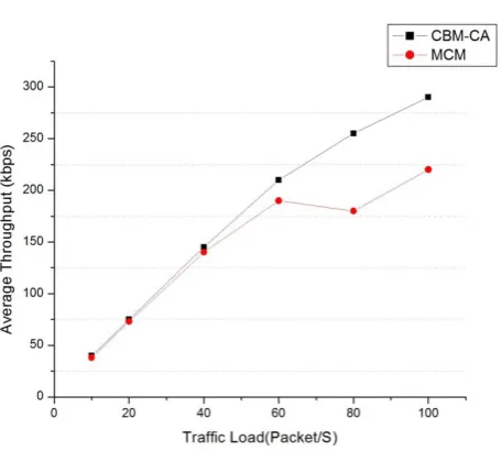
The Figure 4 shows that when the load of the traffic increases, packet delivery ration decreases. For both schemes MCM and CBM-CA we observe that as traffic load increases packet delivery ratio decreases. But we see that our CBM-CA based schemes give the better result as compare to MCM schemes because in our scheme, channel capacity is high at all link and also find that in-terference b/w channel also very low so the ratio of no.
Figure 4. Average PDR.
of packet send and no. of packet receive is high means no. of packet deliver at each link. In the figure we see when traffic load is 10 packet/s then the packet delivery ratio for CBM-CA schemes near about 90% and when the traffic load is 100 packet/s the PDR is above 70% that is good in comparison to MCM.
[image:5.595.310.538.411.605.2]Figure 5. Average Throughput.
increases. In both schemes CBM-CA and MCM it hap-pened that average throughput increases as traffic load increases. But in the case of CBM-CA provide better throughput as compare to MCM because no. of packet delivery rate of each channel in the multicast tree is high as compare to assign the channel in MCM schemes.
In the Figure 6 we observe that as the traffic load in-creases the average end to end delay some times increas-es and some time decreasincreas-es. We observe that for the CBM-CA based schemes the end to end delay is near about 42 ms for the traffic load 10 to 100 packet/s and for MCM 44 ms so we find the end to end delay in case of CBM-CA gives better result due to high capacity. For all three cases, as the sender’s rate increases, the through-put increases as expected; the PDR decreases because higher loads cause more congestion and collisions, re-sulting more packets dropped or damaged.
4.6. Function of Number of Channels
[image:6.595.314.533.85.272.2] [image:6.595.313.533.97.519.2]The number of channels in this set of experiments is va-ried from 1 to 20. The multicast group in the 50-node network has 20 receivers, and its source sends at a rate of 60 pkts/s. This rate yields a moderate load for the given group size in this network.
Figure 7 shows that as the no. of channel increases the packet delivery rate ratio will increase. In the figure we observe that the CBM-CA based schemes show the better result as compare to MCM based channel assignment scheme, as the no. of channel increases the no. of non overlapping channel increases and interference decreases so that PDR increases. In the case of CBM-CA capacity of each link also high with minimum interference so that gives the better result as compare to MCM.
The performance of CBM-CA is only slightly better than of MCM in this set of experiments. In the Figure 8
[image:6.595.313.536.274.717.2]Figure 6. Average End to End Delay.
Figure 7. Packet delivery ratio.
shows the average Throughput for different channels. We observe that average throughput increases as no. of chan-nel increases and see that CBM-CA gives the better re-sult as compare to MCM.
5. Conclusion
In this paper, we proposed the capacity based multicast channel assignment (CBM-CA) algorithm. The optimiza-tion funcoptimiza-tion of the CBM-CA algorithm uses channel se-paration and channel capacity and thus does not rely on the computation of the interference factors. Advantages of our proposed algorithm include its simple implemen-tation and high performance. The effectiveness of the CBM-CA algorithm is maximized in a network where the multicast group (tree) is dense. In such environment, the number of neighbouring nodes around a node is high and thus, without a carefully designed channel assign-ment (CA) algorithm like CBM-CA, the probability of channel conflicts among nodes would be very high. Our simulation results showed that the CBM-CA algorithm outperforms MCM in terms of average PDR, throughput, and end-to-end delay under various traffic loads, group sizes and different number of channels. We introduced an approach based on channel capacity to address the CA problem in multicast WMN to maximize throughput. Our simulation results showed that the CBM-CA algorithm outperforms MCM in terms of average PDR, throughput, and end-to-end delay under various traffic loads, group sizes and different number of channels.
REFERENCES
[1] G. K. Zeng, B. Wang, Y. Ding, L. Xiao and M. W. Mutka, “Efficient Multicast Algorithms for Multichannel Wire- less Mesh Networks,” IEEE Transactions On Parallel And Distributed Systems, Vol. 21, No. 1, 2010.
http://dx.doi.org/10.1109/TPDS.2009.46
[2] S. Sobana and S. Krishna Prabha, “An Efficient Method For Multichannel Wireless Mesh Networks With Pulse Coupled Neural Network,” (IJACSA) International Jour-nal of Advanced Computer Science and Applications, Vol. 3, No. 1, 2012.
[3] J.-W. Lin and S.-M. Lin, “Channel Assignment for Mul- ticast in Wireless Mesh Networks with Considering For- warding Weight and Distance”, 978-1-4244-8728-8/11/ $26.00 ©2011 IEEE.
[4] Z. Y. Yin, Z. C. Li and M. Chen, “A Novel Channel As-signment Algorithm for Multicast in Multi-radio Wireless Mesh Networks,”1-4244-1521-7/07/$25.00 §2007 IEEE
[5] H. Skalli, S. Ghosh and S. K. Das, “Channel Assignment Strategies for Multiradio Wireless Mesh Networks: Issues and Solutions,” IEEE Communications Magazine, 2007. http://dx.doi.org/10.1109/MCOM.2007.4378326
[6] K. Ramachandran, E. M. Belding, K. Almeroth and M. Buddhiko, “Interference-Aware Channel Assignment in Multi-Radio Wireless Mesh Networks,” Proceedings of IEEE INFOCOM, 2006.
http://dx.doi.org/10.1109/INFOCOM.2006.177
[7] J. Tang, G. Xue and W. Zhang, “Maximum Throughput and Fair Bandwidth Allocation in Multi-Channel Wire- less Mesh Networks,” Proceedings of IEEE INFOCOM, 2006.
[8] I. Akyildiz, X. D. Wang and W. L. Wang, “Wireless mesh networks: A Survey,” Computer Networks, 2005. http://dx.doi.org/10.1016/j.comnet.2004.12.001
[9] K. Ramachandran, E. M. Belding, K. Almeroth and M. Buddhiko, “Interference-Aware Channel Assignment in Multi-Radio Wireless Mesh Networks,” Proceedings of IEEE INFOCOM, 2006.
http://dx.doi.org/10.1109/INFOCOM.2006.177
[10] J. Tang, G. Xue and W. Zhang, “Maximum Throughput and Fair Bandwidth Allocation in Multi-Channel Wire- less Mesh Networks,” Proceedings of IEEE INFOCOM, 2006.
[11] J. Tang, G. L. Xue and W. Y. Zhang,” Interference- Aware Topology Control and QoS Routing in Multi- Channel Wireless Mesh Networks,” Proceedings of the Sixth International Symposium on Mobile Ad Hoc Net- working and Computing (MobiHoc 2005), Urbana-Cham- paign, 2005, pp. 68-77.