Evaluation of Unstiffened Extended End Plate Moment Connection
Design Methods for I-Section Steel Beam
Santosh D. Shejwal
1Poonam S. Ingole
2 1ME Student
2Assistant Professor
1
Department of Structures Engineering
2Department of Civil Engineering
1,2
Flora Institute of Technology, Pune, India
Abstract— Extended end plate bolted moment connections are integral part of multi-storeyed steel buildings & Industrial steel buildings. Extended end plate bolted moment connections are provided at beam column joints to achieve rigidity & stiffness to the structures against lateral loads. These lateral loads are induced due to the action of wind, earthquake & vibrations (caused because of man-machine movement). Moment connections are provided for beam & column intermediate splices to achieve flexural continuity over their spans. It is therefore important to identify standard method (analysis-design) & equations for extended end plate bolted moment connections. This Paper aims to study Lever arm method, Triangular force distribution method & Actual neutral axis method for design of extended end plate bolted moment connections. The further work comprises of comparing results obtained from all three methods with results obtained from Finite Element Model prepared in STAAD Pro Software. Most appropriate method showing close resemblance with results of FEA method for design of end plate bolted moment connection is then accepted.
Key words: Steel Buildings, Extended End Plate Bolted Moment Connections, Finite Element Model
I. INTRODUCTION
Moment resisting connections are used in multi-storey un-braced steel buildings and in single-storey portal frame steel buildings. Moment connections can be broadly classified into two types either Cover plate splice connections or End plate moment connections.
A typical cover plate splice connection consist of flange & web cover plates connected with a beam sections to be spliced at their ends with bolts in plane shear. Cover plate splice connections are less popular due to its techno-commercial non viability. In cover plate splice connections numerous bolts and cover plates are required to transfer moments & axial forces. Also site erection efforts are more in case of cover plate splice connections.
[image:1.595.307.546.468.582.2]A typical end-plate moment connection is composed of a steel plate welded to the end of a beam section with attachment to an adjacent member using rows of fully tensioned high-strength bolts. End plate moment connections are commonly used due to ease of fabrication & erection on site.
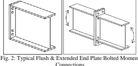
Fig. 1: Typical Bolted Moment Connections End-plate moment connections are classified as either flush or extended,. A flush connection is detailed such that the end plate does not appreciably extend beyond the beam flanges and all bolts are located between the beam flanges. Flush end-plate connections are typically used in frames subject to light lateral loadings or near inflection points of gable frames since lesser amount of moments are generated in such cases. An extended connection is detailed such that the end plate extends beyond the tension flange a sufficient distance to allow a location of bolts other than between the beam flanges. Extended end plates may be used with or without a stiffener between the end plate and the tension beam flange in the plane of the beam web
Fig. 2: Typical Flush & Extended End Plate Bolted Moment Connections
Extended plate moment connections are further classified based on number of bolts on each side of flange, number of rows/columns of bolts & provision of stiffeners.
[image:1.595.311.545.624.768.2]4E 4ES 8ES 8E-4C 8ES-4 Fig. 3: Extended End Plate Moment Connection
[image:1.595.72.264.660.766.2]Extended plate moment connections can be analysed & designed using following two primary methods
A. Bolt Force Method
[image:2.595.49.283.205.289.2]The bolt row furthest from the compression flange will tend to attract the greatest tension force and design practice is to assume a triangular distribution of forces, pro rata to the distance from the bottom flange. However, where the end plate is sufficiently flexible that ductile behaviour is achieved, the full resistances of the lower rows may be used. This is sometimes referred to as a plastic distribution of bolt row forces.
Fig. 4: Schematic of Bolt Force Method
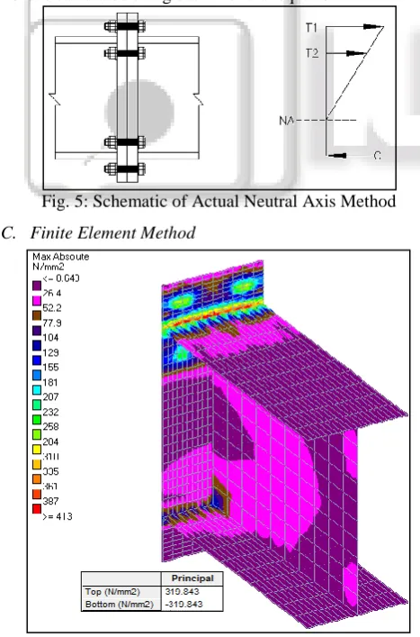
B. Actual Neutral Axis Method
In this method location of actual neutral axis & moment of inertia of bolt group & T-stub (beam flange & web) system is calculated. With known location of neutral axis, tensile stress in extreme bolt fibre & compressive stress in extreme flange fibre is calculated using basic flexural equation.
Fig. 5: Schematic of Actual Neutral Axis Method
C. Finite Element Method
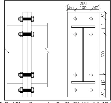
Fig. 6: Finite Element Model of End plate connection In this method Finite Element Model of Bolt group & End plate system is simulated in Finite element Software. (STAAD Pro, Ansys etc) Bolt Force & End Plate Stresses are
calculated by applying design moments in the model. Quadrilateral elements are used for meshing.
In this paper, all the three manual methods described above are studied in detail & design of end plate moment connection is carried out using these methods for selected section. Comparison of these methods has been carried out with results of Finite element model in STAAD Pro software. Equation for Bolt force & Plate thickness in terms of moment as independent variable is established using regression technique.
II. LITERATURE REVIEW
Douty and McGuire. (1965) Performed test on end plate moment connections. They investigated the forces induced in the bolts by the tension flanges. Tests and analytical studies were made of the components and complete assemblies of T-stub moment connections having high strength bolts. (A325) Semi-empirical formulas for estimating prying were presented and incorporated in a tentative design procedure for the use of connections of this type in plastic design.
Ghobarah et al. (1990), Korol et al. (1990) investigated the cyclic behaviour of extended stiffened and unstiffened end plate connections. They recommended that for unstiffened connections, the bolts & end plate shall be designed for 1.3 time’s plastic moment capacity of the beam. It was also recommended that for stiffened connections, the end plate and bolts shall be designed for the plastic moment capacity of the beam.
Borgsmiller (1995) Presented a simplified method for the design of four flush and five extended end plate moment connection configurations. It was concluded that the prying forces in the bolts become significant when ninety percent of end plate strength is achieved. This established a thresh hold for the point at which prying forces in the bolts can be neglected. If applied moment < 90% Plate Capacity, No Prying to be considered & if applied moment > 90% Plate Capacity, Prying Occurs.
Emmet A. Sumner and Thomas M. Murray (2001) investigated the validity of the current design procedures for gravity, wind and low seismic loading. In addition, the tests investigated the effects of standard and large inner pitch distances and the connections utilized both A325 and A490 bolts. It was concluded that large inner pitch distance slightly decreases the strength ratio of thick plate end-plate connections.
Shoemaker and Thomas M. Murray (2002) presented a guide for the design and analysis of flush and extended end-plate moment connections. The guide includes provisions for the design of four flush and five extended end-plate connection configurations. It is based on yield line analysis for the determination of the end plate thickness and the modified Kennedy method for determination of the bolt forces. A stiffness criterion for flush end plate moment connection was also included in the procedure.
[image:2.595.45.279.371.725.2]possible failure modes that could result due to a certain number of failed bolts, analyzing the failure mechanisms with the yield line method.
Emmet A. Sumner and Thomas M. Murray (2015) Presented a design guide for extended end plate moment connections for wind & seismic applications.
In preceding studies & researches, work has been carried out mainly on Behaviour of end plate connections subjected to seismic & cyclic loading. Emphasis has been given on Experimental Testing & Finite Element Analysis to predict moment capacity & rotation capacity of bolted end plate moment connections. Simplified method for the design of Flush and Extended End Plate Bolted Moment connections are explained.
III. OBJECTIVES & METHODOLOGY
A. Analysis & design
Analysis & Design of Unstiffened Extended End Plate Moment Connection of I section Beam by following methods 1) Triangular Force Method
2) Lever Arm Method (Plastic Distribution Method) 3) Actual Neutral Axis Method
4) Finite Element Model (STAAD Pro)
B. Comparison
Results obtained from above mentioned methods are tabulated & manual methods are compared with finite element method results.
C. Graphs
Graphs are plotted for all above mentioned methods for Bolt force vs. applied moment & Plate thickness vs. applied moment.
D. Regression
Mathematical equation for bolt force & plate thickness in terms of applied moment has been formulated using regression for FEM results.
IV. DESIGN CALCULATIONS
I-shaped steel Plastic section mentioned below has been created as per requirements of IS800-2007 code, Table 2, Clause 3.7.2 & 3.7.4. A plastic section is selected so as to develop full plastic moment capacity of the section at the joint. Section details are given below
1) Section Name – W 400x6 & 2F 150x12 2) Clear Depth of Section – 400 mm 3) Web Thickness – 6 mm
4) Flange Width – 150 mm 5) Flange Thickness – 12 mm 6) Cross Section Area – 43686 mm2
Plastic moment capacity for section as mentioned above is calculated as per clause 8.2.1.2, IS800-2007. 1) Mp = β x Zp x Fy/γm0
2) Where,
3) Zp – Plastic Section Modulus 4) Fy – Material Yield Stress 5) γm0 – Partial Safety Factor 6) Mp = 312.3 kN.m
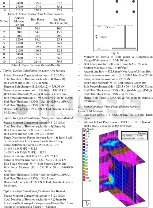
[image:3.595.328.521.102.281.2]Moment connection has been designed for incremental moments starting from 30kN.m to 312.3 kN.m with an interval of 30 kN.m between each case.
Fig. 7: End Plate Connection Profile W 400x6 & 2F 150x12 Following Tables shows results obtained for each case & for all analysis & design methods mentioned earlier. Also typical calculation for each method is illustrated below.
Sr. No
Applied Moment
(kN.m)
Bolt Force (kN)
End Plate Thickness (mm)
1 30.0 18.2 10.7
2 60.0 36.4 15.1
3 90.0 54.6 18.5
4 120.0 72.8 21.4
5 150.0 91.0 23.9
6 180.0 109.2 26.2
7 210.0 127.4 28.3
8 240.0 145.6 30.3
9 270.0 163.8 32.1
[image:3.595.306.553.322.767.2]10 312.3 189.5 34.5
Table 1: Lever Arm Method-Results
Sr. No
Applied Moment
(kN.m)
Bolt Force (kN)
End Plate Thickness (mm)
1 30.0 20.3 11.3
2 60.0 40.6 16.0
3 90.0 60.9 19.6
4 120.0 81.2 22.6
5 150.0 101.5 25.3
6 180.0 121.8 27.7
7 210.0 142.1 29.9
8 240.0 162.4 32.0
9 270.0 182.7 33.9
10 312.3 211.4 36.5
Table 2: Triangular Force Method-Results
Sr. No
Applied Moment
(kN.m)
Bolt Force (kN)
End Plate Thickness (mm)
1 30.0 22.0 11.7
2 60.0 43.9 16.6
3 90.0 65.9 20.3
4 120.0 87.8 23.5
5 150.0 109.8 26.3
7 210.0 153.7 31.1
8 240.0 175.6 33.2
9 270.0 197.6 35.2
[image:4.595.51.551.76.754.2]10 312.3 228.5 37.9
Table 3: Actual Neutral Axis Method-Results
Sr. No
Applied Moment
(kN.m)
Bolt Force (kN)
End Plate Thickness (mm)
1 30.0 30.4 10.0
2 60.0 54.8 15.7
3 90.0 75.6 20.0
4 120.0 94.0 23.8
5 150.0 112.0 26.9
6 180.0 129.5 29.7
7 210.0 146.8 32.4
8 240.0 164.5 34.5
9 270.0 181.9 36.8
10 312.3 214.6 39.5
Table 4: Finite Element Method-Results
A. Typical Design Calculation for Lever Arm Method
Plastic Moment Capacity of section = 312.3 kN.m Total Number of Bolts on each side = 4(24mm Φ) Bolt Lever arm = 400+12 = 412mm
Force in Bolt Group = (312.4/0.412) = 758.08 kN Force in extreme row bolt = 758.08/4 = 189.52 kN Bolt Force Moment (M) = (Bolt Force x Lever arm) Bolt Force Moment (M) = 189.52 x 50 = 9476000 N.mm End Plate Thickness (E350) = Sqrt ((4xMxγm0)/(PxFy)) End Plate Thickness (E350) = 34.52 mm
Hence Bolt Force is 189.52 kN & End plate thickness is 34.52 mm.
B. Typical Design Calculation for Triangular Force Method
Plastic Moment Capacity of section = 312.3 kN.m Total Number of Bolts on each side = 4(24mm Φ) Bolt Lever arm for Bolt Row 1 = 468mm
Bolt Lever arm for Bolt Row 2 = 356mm
Force Distribution Factor between Row 1 & Row 2 will be ration of their Lever arms form bottom Flange. Force distribution Factor = (356/468) = 0.761 0.468F1 + 0.356F2 = 312.3
0.468F1 + 0.356(0.761F1) = 312.3
Force in Extreme Bolt Row F1 = 422.75 kN Force in extreme row bolt = 422.75/2 = 211.37 kN Bolt Force Moment (M) = (Bolt Force x Lever arm) Bolt Force Moment (M) = 211.37 x 50 = 10568000
N.mm
End Plate Thickness (E350) = Sqrt ((4xMxγm0)/(PxFy)) End Plate Thickness (E350) = 36.45 mm
Hence Bolt Force is 211.37 kN & End plate thickness is 36.45 mm.
C. Typical Design Calculation for Actual NA Method
Plastic Moment Capacity of section = 312.3 kN.m Total Number of Bolts on each side = 4 (24mm Φ) Location of bolt group & Compression Flange/Web from
bottom of compression Flange = 152mmm
Fig. 8:
Moment of Inertia of Bolt group & Compression
Flange/Web system = 15.54x107 mm4
Bolt Lever arm for Bolt Row 1 from NA = 322 mm Section Modulus = 482.16*103mm3
Area of one Bolt = 352.8 mm2 (Net Area of 24mm Bolt) Force in extreme row bolt = (312.3/482.16x103)x352.88 Force in extreme row bolt = 228.5 kN
Bolt Force Moment (M) = (Bolt Force x Lever arm) Bolt Force Moment (M) = 228.5 x 50 = 11425000 N.mm End Plate Thickness (E350) = Sqrt ((4xMxγm0)/ (PxFy)) End Plate Thickness (E350) = 37.90 mm
Hence Bolt Force is 228.5 kN & End plate thickness is 37.90 mm.
D. Typical analysis View Finite Element Method
From FEM Analysis,
End Plate Stress = 318.642 N/mm2 for 39.5mm Thick plate
Allowable End Plate Stress = 350/1.1 = 318.18 N/mm2 Bolt Force = 214.6 kN at top Row Bolt
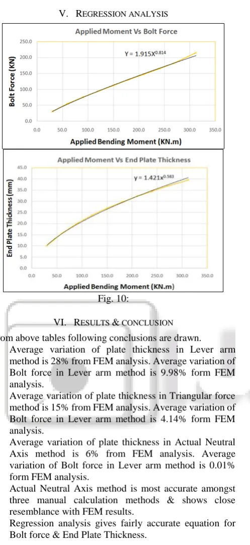
V. REGRESSION ANALYSIS
Fig. 10:
VI. RESULTS & CONCLUSION
From above tables following conclusions are drawn.
1) Average variation of plate thickness in Lever arm method is 28% from FEM analysis. Average variation of Bolt force in Lever arm method is 9.98% form FEM analysis.
2) Average variation of plate thickness in Triangular force method is 15% from FEM analysis. Average variation of Bolt force in Lever arm method is 4.14% form FEM analysis.
3) Average variation of plate thickness in Actual Neutral Axis method is 6% from FEM analysis. Average variation of Bolt force in Lever arm method is 0.01% form FEM analysis.
4) Actual Neutral Axis method is most accurate amongst three manual calculation methods & shows close resemblance with FEM results.
5) Regression analysis gives fairly accurate equation for Bolt force & End Plate Thickness.
REFERENCES
[1] R.T. Douty, W. McGuire, “High Strength Bolted Connections with Applications to Plastic Design”, University of Missouri, Columbia, 1965.
[2] R.M. Korol, A. Ghobarah, A. Osman, “Simplified Methods for Design of Moment End Plate Connections”, McMaster University, Canada, 1990.
[3] Jeffrey T. Borgsmiller, “Extended End Plate Connections under Cyclic Loading: Behaviour & Design”, Virginia Polytechnic Institute & State University, United States of America, 1995.
[4] Emmet A. Sumner, Thomas M. Murray, “Experimental Investigation of the Multiple Row Extended ½ End Plate
Moment Connection”, Metal Building Manufacturers Association, Cleveland, Ohio, United States of America, 2001.
[5] Emmet A. Sumner, Thomas M. Murray, “Unified Design of Extended End Plate Moment Connections Subjected to Cyclic Loading”, Virginia Polytechnic Institute & State University, United States of America, 2003. [6] Emmet A. Sumner, Thomas M. Murray, “Unified Design
of Extended End Plate Moment Connections Subjected to Cyclic Loading”, Virginia Polytechnic Institute & State University, United States of America, 2003. [7] John C. Ryan. Jr, “Evaluation of Extended End-Plate
Moment Connections under Seismic Loading”, Virginia Polytechnic Institute & State University, United States of America, 2009.