Analysis of Tilting Train Mechanism - A Technical Report
Shubham Sinha
1Prakash Markande
21
FMPE, IGKV Raipur, India
2Government Engineering College, Jagdalpur, India
Abstract— Transportation is the basic need of daily life due to which all the resources and the services are provided easily and on a systematic way. One of the most considerable example of the transportation is the train. People used to refer the train as a regular transport and travel option. In this work we are working on the suspension system of the train bogies so that travelling could become smoother and more comfortable without any disturbance of roughness and discomfort. To the structural engineer, damping means changes in overall stress within a structure subject to shock and vibration, with frequent arguments whether a structure will have "2%, 3%, 4%, but not more than 5%" structural damping. On the other hand, mechanical engineers do not necessarily view damping as a benevolent feature, since machines, by definition, are supposed to transmit forces and motions efficiently, without energy losses. Thus the need for damping in a machine often signifies that an engineering design error has been made. A tilting train is a train that has a mechanism enabling increased speed on regular rail tracks. As a train (or other vehicle) rounds a curve at speed, objects inside the train experience inertia. This can cause packages to slide about or seated passengers to feel squashed by the outboard armrest due to its centripetal force, and standing passengers to lose their balance. Tilting trains are designed to counteract this discomfort. In a curve to the left, the train tilts to the left to compensate for the g-force push to the right, and vice versa. The train may be constructed such that inertial forces cause the tilting (passive tilt), or it may have a computer-controlled power mechanism (active tilt).
Keywords: Train Wagon, Suspension System
I. INTRODUCTION
The basic requirement of the railway is to be reliable, efficient, and cost-effective compared to the other modes of transport. The main prerequisites for meeting these requirements are continuous improvements of design and quality maintenance of railway vehicles and railway infrastructure. The failures on railway do not happen often, but when it happens, the consequence is usually derailment accompanied with enormous material damage and loss of human life. In addition, there is huge material loss caused by the interruption of the traffic and reparation of the infrastructure. One of the most important parameters which determine the reliability and running safety of railway vehicles is functionality of the suspension system. In addition, the functionality of the suspension system affects the quality of ride comfort of passengers or cargo. Inadequate functioning of suspension system causes very serious consequences and in many cases may cause derailment. For this reason, the fault of suspension system is very important topic that is the subject of many scientific papers. The design and reliability of suspension systems in rail vehicle has previously been the subject of many papers, including those concerning the detection of faults [1–5] and analysis of failures [6,7]. The aim of all these researches was to indicate the potential problems and to give the motivation for
improvements in existing or newly-designed solutions of suspension systems.
II. LITERATURE REVIEW
Lei et al. 2018 presented a theoretical framework for modeling the railway wagon-ballast track interactions is presented, in which the dynamic equations of motion of wagon-track systems are constructed by effectively coupling the linear and nonlinear dynamic characteristics of system components. For the linear components, the energy-variational principle is directly used to derive their dynamic matrices, while for the nonlinear components, the dynamic equilibrium method is implemented to deduce the load vectors, based on which a novel railway wagon-ballast track interaction model is developed, and being validated by comparing with the experimental data measured from a heavy haul railway and another advanced model. With this study, extensive contributions in figuring out the critical speed of instability, limits and localizations of track irregularities over derailment accidents are presented by effectively integrating the dynamic simulation model, the track irregularity probabilistic model and time-frequency analysis method.
Finally, through application and solution of one case, validity and practicability of model and algorithm had been proved. So, the model could offer decision support to transport enterprises on adjusting empty wagons.
Josef Soukup et al. presented a assessment of railway wagon suspension characteristics. The essential characteristics of a suspension are represented by the stiffness constants of the equivalent springs and the eigen frequencies of the oscillating movements in reference to the main central inertia axes of a vehicle. The premise of the experimental determination of these characteristic is the knowledge of the gravity center position and the knowledge of the main central inertia moments of the vehicle frame. The vehicle frame performs the general spatial movement when the vehicle moves. An analysis of the frame movement generally arises from Euler's equations which are commonly used for the description of the spherical movement. This solution is difficult and it can be simplified by applying the specific assumptions. The eigen frequencies solutions and solutions of the suspension stiffness are presented in the article. The solutions are applied on the railway and road vehicles with the simplifying conditions. A new method which assessed the characteristics is described in their work
Yu-Jun et al.2014 proposes a mathematical model for emergency railway wagon scheduling, which considers multiple target stations requiring relief supplies, source stations for providing supplies, and central stations for allocating railway wagons. Under the emergency environment, the aim of the problem is to minimize the weighted time for delivering all the required supplies to the targets. For efficiently solving the problem, we develop a new hybrid biogeography-based optimization (BBO) algorithm, which uses a local ring topology of population to avoid premature convergence, includes the differential evolution (DE) mutation operator to perform effective exploration, and takes some problem-specific mechanisms for fine-tuning the search process and handling the constraints.
III. TILTING TRAIN MECHANISM
[image:2.595.308.549.316.472.2]A tilting train is a train that has a mechanism enabling increased speed on regular rail tracks. As a train (or other vehicle) rounds a curve at speed, objects inside the train experience inertia. This can cause packages to slide about or seated passengers to feel squashed by the outboard armrest due to its centripetal force, and standing passengers to lose their balance.
Fig. 2: Tilting train mechanism
Tilting trains are designed to counteract this discomfort. In a curve to the left, the train tilts to the left to compensate for the g-force push to the right, and vice versa. The train may be constructed such that inertial forces cause the tilting (passive tilt), or it may have a computer-controlled power mechanism (active tilt).
IV. CALCULATION AND ANALYSIS
While a qualitative description provides some understanding of the phenomenon, deeper understanding inevitably requires a mathematical analysis of the vehicle dynamics. Even then, the results may be only approximate.
[image:2.595.46.295.602.754.2]A kinematic description deals with the geometry of motion, without reference to the forces causing it, so the analysis begins with a description of the geometry of a wheel set running on a straight track. Since Newton's Second Law relates forces to accelerations of bodies, the forces acting may then be derived from the kinematics by calculating the accelerations of the components. However if these forces change the kinematic description (as they do in this case) then the results may only be approximately correct.
Fig. 3: Kinematics of railway wheel coning action V. MATHEMATICAL ANALYSIS
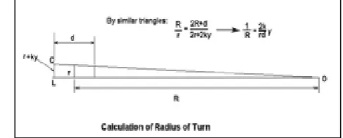
The train stays on the track by virtue of the conical shape of the wheel treads. If a wheel set is displaced to one side by an amount "y" (the tracking error), the radius of the tread in contact with the rail on one side is reduced, while on the other side it is increased. The angular velocity is the same for both wheels (they are coupled via a rigid axle), so the larger diameter tread speeds up, while the smaller slows down. The wheel set steers around a center of curvature defined by the intersection of the generator of a cone passing through the points of contact with the wheels on the rails and the axis of the wheel set. Applying similar triangles, we have for the turn radius:
[image:2.595.302.546.656.754.2]Where d is the track gauge, r the wheel radius when running straight and k is the tread taper (which is the slope of tread in the horizontal direction perpendicular to the track).
The path of the wheel set relative to the straight track is defined by a function y(x) where x is the progress along the track. This is sometimes called the tracking error.Provided the direction of motion remains more or less parallel to the rails, the curvature of the path may be related to the second derivative of y with respect to distance along the track as approximately.
It follows that the trajectory along the track is governed by the equation.
This is simple harmonic motion having wavelength:
Known as Klingel's formula (derived in 1883) This kinematic analysis implies that trains sway from side to side all the time. In fact, this oscillation is damped out below a critical speed and the ride is correspondingly more comfortable. The kinematic result ignores the forces causing the motion. These may be analyzed using the concept of creep (non-linear) but are somewhat difficult to quantify simply, as they arise from the elastic distortion of the wheel and rail at the regions of contact. These are the subject of frictional contact mechanics; an early presentation that includes these effects in hunting motion analysis was presented by Carter. See the for a historical overview. If the motion is substantially parallel with the rails, the
angular displacement of the wheel set is given by:
Hence:
The angular deflection also follows a simple harmonic motion, which lags behind the side to side motion by a quarter of a cycle. In many systems which are characterized by harmonic motion involving two different states (in this case the axle yaw deflection and the lateral displacement), the quarter cycle lag between the two motions endows the system with the ability to extract energy from the forward motion. This effect is observed in "flutter" of aircraft wings and "shimmy" of road vehicles, as well as hunting of railway vehicles. The kinematic solution derived above describes the motion at the critical speed.
In practice, below the critical speed, the lag between the two motions is less than a quarter cycles so that the motion is damped out but, above the critical speed, the lag is greater than a quarter cycles so that the motion is amplified.
In order to estimate the inertial forces, it is necessary to express the distance derivatives as time derivatives. This is done using the speed of the vehicle U, which is assumed constant:
The angular acceleration of the axle in yaw is:
The inertial moment (ignoring gyroscopic effects) is:
Where F is the force acting along the rails and C is the moment of inertia of the wheel set.
The maximum frictional force between the wheel and rail is given by:
Where W is the axle load and is the coefficient of friction. Gross slipping will occur at a combination of speed and axle deflection given by:
This expression yields a significant overestimate of the critical speed, but it does illustrate the physical reason why hunting occurs, i.e. the inertial forces become comparable with the adhesion forces above a certain speed. Limiting friction is a poor representation of the adhesion force in this case.
The actual adhesion forces arise from the distortion of the tread and rail in the region of contact. There is no gross slippage, just elastic distortion and some local slipping (creep slippage). During normal operation these forces are well within the limiting friction constraint. A complete analysis takes these forces into account, using rolling contact mechanics theories. However, the kinematic analysis assumed that there was no slippage at all at the wheel-rail contact. Now it's clear that there is some creep slippage which makes the calculated sinusoidal trajectory of the wheel set (per Klingle's formula) not exactly correct.
A. Energy balance
In order to get an estimate of the critical speed, we use the fact that the condition for which this kinematic solution is valid corresponds to the case where there is no net energy exchange with the surroundings, so by considering the kinetic and potential energy of the system, we should be able to derive the critical speed.
Let:
Using the operator:
Integrating:
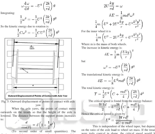
[image:4.595.43.545.63.496.2]So the kinetic energy due to rotation is:
Fig. 5: Outward displacement of points of contact with axle yaw
When the axle yaws, the points of contact move outwards on the treads so that the height of the axle is lowered. The distance between the support points increases to:
(To second order of small quantities). The displacement of the support point out from the centers of the treads is:
The axle load falls by
The work done by lowering the axle load is therefore:
This is energy lost from the system, so in order for the motion to continue, an equal amount of energy must be extracted from the forward motion of the wheel set.
The outer wheel velocity is given by:
The kinetic energy is:
The motion will continue at constant amplitude as long as the energy extracted from the forward motion, and manifesting itself as increased kinetic energy of the wheel set at zero yaw, is equal to the potential energy lost by the lowering of the axle load at maximum yaw.
Now, from the kinematics:
For the inner wheel it is
Where m is the mass of both wheels. The increase in kinetic energy is:
but
The translational kinetic energy is
The total kinetic energy is:
The critical speed is found from the energy balance:
Hence the critical speed is given by
This is independent of the wheel taper, but depends on the ratio of the axle load to wheel set mass. If the treads were truly conical in shape, the critical speed would be independent of the taper. In practice, wear on the wheel causes the taper to vary across the tread width, so that the value of taper used to determine the potential energy is different from that used to calculate the kinetic energy. Denoting the former as a, the critical speed becomes:
Where a is now a shape factor determined by the wheel wear. This result is derived in from an analysis of the system dynamics using standard control engineering methods.
VI. CONCLUSION
REFERENCES
[1] Huichuan Fan, Xiukun Wei, Limin Jia, Yong Qin. Fault detection of railway vehicle suspension systems. Computer Science and Education (ICCSE). 5th International conference on computer, science and
education; 2010. p. 1264–69.
doi:10.1109/ICCSE.2010.5593724.
[2] X.J. Ding, T.X. Mei. Fault detection for vehicle suspensions based on system dynamic interactions. In: Proceedings of the UKACC international conference on control; 2008.
[3] Xiukun Wei, Hai Lui, Yong Qin. Fault isolation of rail vehicle suspension systems by using similarity measure. 2011 IEEE international conference on service operations and logistics and informatics (SOLI); 2011. p. 391–96. doi:10.1109/SOLI.2011.5986591.
[4] Yusuke Hayashi, Hitoshi Tsunashima, Yoshitaka Marumo. Fault detection of railway vehicle suspension systems using multiple-model approach. J Mech Syst
Transportat Logist 2008;1(1):88–99.
http://dx.doi.org/10.1299/jmtl.1.88.
[5] Chamseddine A, Noura H, Raharijaona T. Full vehicle active suspension: sensor fault diagnosis and fault tolerance. IFAC Proc Vol 2006;6(Part 1):468–73 [IFAC-Papers Online].
[6] Kumbhalkar MA, Yenarkar YL, Grover AK. Failure analysis of inner suspension spring of Railway engine: a case study, Proc. int. conf. on advances in robotic. Mech Eng Des 2011:12–6. doi:02.ARMED.2011.01.2. [7] Secondary suspension failure on a train at Connolly
Station. 7th May 2010. Investigation report 2011–R002. Railway Accident Investigation Unit – RAIU;2011. [8] Lei Xu, Xianmai Chen, Xuwei Li, Xianglin He,
“Development of a railway wagon-track interaction model: Case studies on excited tracks”, Mechanical Systems and Signal Processing, Volume 100, 1 February 2018, Pages 877-898
[9] Krasoń Wiesław, Niezgoda Tadeusz, Stankiewicz Michał, “Innovative Project of Prototype Railway Wagon and Intermodal Transport System”, Transportation Research Procedia, Volume 14, 2016, Pages 615-624
[10] Jinchuan Zhang, Hao Yang, Yuguang Wei, Pan Shang, “The empty wagons adjustment algorithm of Chinese heavy-haul railway”, Chaos, Solitons & Fractals, Volume 89, August 2016, Pages 91-99
[11] Josef Soukup, Jan Skočilas, Blanka Skočilasová, “Assessment of railway wagon suspension characteristics”, Mechanical Systems and Signal Processing, Volume 89, 15 May 2017, Pages 67-77 [12] Yu-Jun Zheng, Hai-Feng Ling, Hai-He Shi, Hai-Song