IMPLEMENTATION OF FUZZY-NEURO CONTROLLER FOR DC-DC
CONVERTER FED DC SERIES MOTOR USING EMBEDDED
MICROCONTROLLER
I. Thangaraju1 M. Muruganandam2 and M. Madheswaran3
1Department of Electrical and Electronics Engineering, Government College of Engineering, Bargur, Tamilnadu, India 2Department of Electrical and Electronics Engineering, Muthayammal Engineering College, Rasipuram, Tamilnadu, India 3Department of Electronics and Communication Engineering, Mahendra Engineering College, Mallasamudram West, Tamilnadu, India
E-Mail: [email protected]
ABSTRACT
The speed control of a DC series motor with Hybrid Fuzzy-Neuro Controller (FNC) is presented in this paper. The motor is connected with a DC Chopper. This configuration has been designed with current control and speed control loops. The current controller blocks the PWM signal when the current increases beyond its limit. The speed controller is based on Fuzzy-Neuro type. The performances of FNC are analyzed in respect of load variation and speed variation using MATLAB/Simulink. This system is implemented in NXP 80C51 Microcontroller based Embedded System. From the result of simulation and hardware implementation it is found that the FNC can have better control compared with Fuzzy Logic Controller (FLC).
Keywords: DC Series Motor, Fuzzy - Neuro Controller, DC Chopper, MATLAB Simulink, Embedded System.
1. INTRODUCTION
DC series motor is normally utilized for high torque applications. In such a way, that the DC series motor drives are engaged with many applications to handle heavy load, as they offer high starting torque. Most of their applications are of an industrial nature such as lifts, cranes, hoist and electric traction. DC series motors are an ideal choice for battery-operated equipment over AC motors, as they do not require the use of expensive inverter circuitry to convert the DC voltage to an AC voltage required by the motor. Here the DC series motor is controlled by DC chopper. The duty cycle is varied to get variable output voltage in the chopper [1]. The DC series motor in industrial environment has increased due to high performance and high starting torque for a particular drive system. Such a high performance applications requires the motor drive with least steady state error, over shoot, under shoot and the settling time in its speed characteristic. It is noted that the intelligent control based Artificial Neural Network (ANN) can give the better performance for a nonlinear parameter varying system with load torque disturbance.
The conventional controllers like PI, PID and Fuzzy Logic Controllers were widely used formerly for chopper control and motor control applications [2]. Although the performance of such controller is deprived and it failed to give suitable results when control parameters, loading conditions and the motor itself are changed. Thus the tuning and optimization of these controllers are a challenging and difficult task, particularly under varying load conditions, parameter changes and abnormal modes of operation. The main disadvantage with the conventional controller is the high computation time. It
has been found that the computation burden of Fuzzy Logic Controller can be reduced by hybrid Fuzzy-Neuro Controller. Intelligent control techniques involving ANN is found to be simpler for implementation and powerful in control applications [3]. The ANN controller is simulated using MATLAB GUI nntool [4].
The DC series motor drive fed by a single phase controlled rectifier (AC to DC converter) and controlled by fuzzy logic is presented. It was concluded that the fuzzy logic controller provides better control over the classical PI controller which has improved the performance. It was also reported that the settling time and maximum overshoot can be reduced [5]. A low-cost fuzzy controller for the control of DC drive fed by four-quadrant chopper was designed and utilised. The fuzzy controller was implemented in a low-cost 8051 microcontroller. The simulated closed loop performance of the fuzzy controller in respect of load variation and reference speed change has been reported [6].
A fuzzy controller was designed for closed loop control of DC series motor drive fed by DC-DC converter. The performance in respect of load variation and speed changes has been reported. The performance of the proposed controller was compared with the reported results and found that the fuzzy based DC-DC drive can have better control [7]. The fuzzy logic controller was utilized for different types of DC drives [8].
obtained from the conventional PI controller also from fuzzy logic controller. The designed controller was implemented in a low cost 8051 Microcontroller [10].
The Neuro-Fuzzy control was applied to a DC series motor. Fuzzy logic suffers from complex data processing. This problem was resolved by implementing a fuzzy logic controller on a neural network [11]. The Fuzzy Logic Controller is implemented in a Neural Network and utilized for separately excited DC motor. The experimental responses demonstrate the effectiveness of the proposed system [12]. A feed forward ANN was developed for the speed control of DC motor. The network was randomly trained by online training methods. The proposed controller simplifies the learning algorithm, reduces the computation time and accelerates the training speed [13].
An adaptive Neuro-Fuzzy controller for the control of DC motor speed was designed and simulated. The proposed system result demonstrates that the deigned ANFIS Swarm speed controller appreciate a good dynamic behavior of the DC motor speed control with no overshoot, better performance and high robustness [14]. A new simulator model for a winding process using non-linear identification based on a recurrent local non-linear neuro-fuzzy network trained by local linear model tree, which was an incremental tree-based learning algorithm. The experimental results illustrate the effectiveness of the proposed Neuro-Fuzzy modeling approach [15].
The PID-ANN controlled DC-DC converter fed PMDC motor is presented. The PID-ANN controller gives the proper speed regulation from 10% to 100% load disturbance than the conventional PID controller [16]. Artificial neural network-based tracking controller for high-performance stepper motor drives is implemented. The experimental results have shown that the proposed control structure tracks the trajectories successfully, even under external disturbances and noisy environment [17]. A hybrid neuro-fuzzy controller (NFC) is presented for the speed control of Brushless DC motors to improve the control performance of the drive under transient and steady state conditions [18]. Fuzzy-Neuro control architecture is applied to Brushless DC motor and implemented in real time using a digital signal processor [19]. An adaptive neuro-fuzzy inference system (ANFIS) has been used to control the speed of the switched reluctance motor. The ANFIS algorithm has been implemented on a digital signal processor (TMS320F240) allowing great flexibility for various real time applications [20].
The Neuro-Fuzzy (NF) hybrid system is design and implemented for Sumo Robot (SR) control. The results showed that intelligent control and soft computing techniques can be easily applied to various robotic competitions [21]. Neuro-Fuzzy based navigation techniques for several mobile robots are investigated in a totally unknown environment. By using Neuro-Fuzzy technique as many as 1,000 mobile robots can navigate
successfully neither collides with each other nor colliding with the obstacles present in the environment. It is concluded that the developed Neuro-Fuzzy technique is most efficient [22-23].
In the proposed system a Fuzzy-Neuro controller is designed. The motor drive system mainly utilizes the FNC and DC chopper (DC-DC converter). Such a drive system has the characteristics of precise, fast, effective speed reference tracking with minimum overshoot/undershoot and minimal steady state error. The FNC based speed controller work effectively under input voltage variation and load torque disturbances also it will work excellently even the motor parameters changes. Hence the system is made for a series motor with different load and different speed. In order to maintaining the current at a limiting value an ON/OFF type current controller is also designed, it will limit the current in a safe value.
2. PROPOSED SYSTEM
The block diagram of the proposed system is shown in Figure-1. The system mainly consists of DC chopper to drive the DC motor. A pulse type tacho generator is used as a speed sensing element and which is used for speed feedback to the controller. A micro-controller or a digital signal processor can be used to generate the PWM signal to switch the DC chopper, during the implementation of experimental setup. In this work a NXP 80C51 family Microcontroller (P89V51RD2BN) based Embedded System is utilized.
Figure-1. Block diagram of the proposed system.
pulse type tacho generator and given to the ADC of microcontroller, the set speed r(k) also given to the ADC and the error signal e(k) is obtained by comparing the set speed r(k) with the actual speed (k). The change in error e(k) is obtained from the present error e(k) and pervious error eprevious(k).
The error and change in error are given as inputs to the FNC. The output of the FNC is denoted as duty cycle. The change in duty cycle dc(k) for the DC chopper is calculated from the new duty cycle dc(k) and previous duty cycle dc(k-1). The input and output gain of the FNC can be estimated by simulation. The FNC can reduce the error to zero by changing the duty cycle of the switching signal to the DC chopper [7-8].
3. MATHEMATICAL MODELING OF DC SERIES MOTOR AND DC CHOPPER
3.1 DC series motor model
From the general equivalent circuit of DC series motor the voltage and torque equations are obtained, which is given in equation (1) and (2) respectively.
Consider, Ra Rarm Rse ; LaLarm Lse+2M
res b a a a a
o e e
dt di L R i
V (1)
L
T
B
dt
d
J
T
(2)where, ia = ise - Motor current V0 = Motor terminal voltage Rarm = Armature resistance Rse = Series field resistance Ra = Total resistance Larm = Armature inductance Lse = Series field inductance La = Total inductance M = Mutual inductance eb = Back emf
eres = emf due to residual magnetic flex T = Deflecting torque
J = Moment of inertia B = Friction coefficient
=
dt
d
= Angular speed
= Angular displacement = Series field flux TL = Load torque
Kaf = Armature voltage constant and
Kres = Residual mag. Voltage const.
) .
(ieBeforeSaturaion
i and
eb
a
ab i
e
; ebKaf ia
Speed Angular dt d
Similarly, eres
; eres Kres
dt d K
eres res
By rearranging the equation (1) by replacing eb and eres
dt d K dt d i K dt di L i R
V af a res
a a a a o
(3)
dt d K dt d i K i R V L dt di res a af a a o a
a 1
(4)Similarly the torque equation also derived as follows,
)
(
Before
Saturation
i
and
i
T
a
a2 a
i
T
;T
K
afi
a2 ;AngularSpe
ed
dt
d
By rearranging the equation (2) by replacing T
L a af
T
dt
d
B
dt
d
J
i
K
2
22
(5)
K
afi
aB
T
L
J
dt
d
1
2
(6)
The DC series motor is modeled using the modeling equations (4) and (6). Such an equation modeling is more effective than the transfer function model. In transfer function model, it is mandatory to develop different model for every input and output parameter changes. In this modeled equation modeling the voltage and load torque are the input parameters, the output parameters are speed, current and deflecting torque etc.
3.2 DC chopper
switching device. In order to get high switching frequency (upto 100 KHz) the Power MOSFET may be taken as a switching device also the on state voltage drop in the switch is small and it is neglected. Hence the power MOSFET is designated as a switching device for the DC chopper. When the gate pulse is applied the device is turned on during the period the input supply connects with the load. When the gate pulse is removed the device is turned off and the load disconnected from the input supply.
4. SIMULATION OF THE SYSTEM USING MATLAB / SIMULINK
4.1 Simulation of fuzzy logic controller
Initially a fuzzy logic controller is designed and simulated with DC series motor model. The performance of the fuzzy logic controller was examined with MATLAB/Simulink in terms of speed variation and load variation. The designed FLC is explained in this section. The fuzzy logic has emerged as a tool to deal with uncertainty, imprecise or qualitative decision making problems [5]. The FLC involves three stages namely Fuzzification, Rule-Base and Defuzzification. There are two types of FLC named Mamdani type and Sugeno type. In this work the Sugeno type controller is utilized because it has a singleton membership function in the output variable. Moreover it can be easily implemented and also the number of calculations can be reduced [6].
4.1.1 Fuzzification
In Fuzzy logic system the linguistic variables are used instead of numerical variables. The process of converting a numerical variable (real number or crisp variables) in to a linguistic variable (fuzzy number or fuzzy variable) is called fuzzification.
In this work, the motor speed is controlled by FLC. The error e(k) and change in error e(k) is given to the FLC as input variable. As explained in section 2 the error is calculated by comparing the actual speed (k) with reference speed r(k). From the error e(k) and pervious error epervious (k) the change in error e(k) is calculated. Then the error and change in error are fuzzified [7]. The equation for error and change in error are specified in equation (7) and (9).
( )
r( )
( )
e k
k
k
(7)( )
( )
Pervious( )
e k
e k
e
k
(8)Five linguistic variables were used for the each input variable error e(k) and change in error e(k). Those are Negative Big (NB), Negative Small (NS), Zero (Z), Positive Small (PS) and Positive Big (PB). In FLC there
are many types of membership functions available, those are triangular-shaped, Gaussian, sigmoidal, pi-shaped, trapezoidal-shaped, bell-shaped etc. In this work the triangular membership function is used for simplicity and also to reduce the calculations [8]. Normally seven membership functions are preferred for accurate result [5]. In this present work only five membership functions are used for the input variables error and change in error. In order to reduce the number of membership function and maintain the same performance characteristics the width of the membership functions are kept different [7]. Here the width of center membership function is considered narrow and it is wide towards outer. The input and output fuzzy membership functions are shown in Figure-2.
Figure-2. Fuzzy memberships used for simulation.
4.1.2 Rule table and inference engine
According to general knowledge of the system behavior, the perception and experience, the control rules are derived between the fuzzy outputs to the fuzzy inputs. However, some of the control rules are developed using “trial and error” method.
Table-1. Fuzzy Rules.
NB NS Z PS PB
NB NB NB NB NS Z
NS NB NB NS Z PS
Z NB NS Z PS PB
PS NS Z PS PB PB
In general the rules can be written as “if e(k) is X and e (k) is Y, then dc(k) is Z”,where X, Y and Z are the fuzzy variable for e(k), e(k) and dc(k) respectively. The rule table for the designed fuzzy controller is specified in the Table-1 [8]. The element in the first row and first column means that if erroris NB, and change in error is NB then output is NB.
4.1.3 Defuzzification
The inverse process of fuzzification is called defuzzification. In this process the linguistic or fuzzy variables are converted in to numerical or crisp variable [6]. Here the best well-known weighted sum method is considered for defuzzification method. The defuzzified output is the duty cycle dc(k). The change in duty cycle dc (k) can be obtained by adding the pervious duty cycle dcprevious (k) with the duty cycle dc(k) which is specified in equation (9).
( )
( )
( )
dc k
dc k
pdc k
(9)This type of controllers can be easily implemented in any embedded system. The Sugeno type of controller is selected mainly for implementation in real-time embedded based processors [6]. The designed FLS is simulated with DC series motor through DC chopper. The performance characteristics of speed variation and load changes with FLC fed DC series motor is given in section 5 as result and discussion. But the performance of FLC fed DC series motor is not satisfactory. The main disadvantage with the FLC is the high computation time. It is found that the computation burden of FLC can be reduced by hybrid Fuzzy-Neuro Controller. The ANN required training data to train the neurons in the ANN controller. The designed FLC is simulated with the drive system for extracting the training data.
The Fuzzy Logic controlled DC series motor was simulated for 5 seconds with the sampling time of 0.0001seconds. Totally 50001 data is obtained from the system with FLC. Out of 50001 only 6000 data are taken for training the ANN controller by removing the same value of data.
4.2 Simulation of Fuzzy-Neuro Controller (FNC) The performance of FLC based control of DC series motor is depicted in reference [7]. But the results are needed to be improved further. In order to improve the performance of DC series motor, the Fuzzy-Neuro based controller (FNC) is designed. The Artificial Neural Network control algorithm is designed with the outcome of Fuzzy Logic controller data. The Hybrid Fuzzy-Neuro controller is working properly because of its trained network and also it reduces the computational time. In this section, the implementation of FLC in ANN is presented.
The ANN controller uses a complex network structure in many works. In this work a simple ANN controller is designed with few neurons and one hidden layer. The feed forward neural network is formed with two neurons in the input layer, three in the hidden layer and one neuron in the output layer.
The error e(k) and change in error e(k) are the two inputs of the designed network and the neurons are biased properly. The pure linear activation function is used for input and hidden neurons, the tangent sigmoidal activation function for output neuron. The designed network is then trained with the set of inputs and desired outputs from the FLC [6]. A supervised feed forward back propagation neural network-training algorithm is used and it is trained with minimum error goal. The output of the network is change in the duty cycle dc(k).
Figure-3. Performance plot of ANN during training.
The designed ANN is trained with the error goal of 0.0067113 at 11 epochs. The performance plot of ANN during supervised back propagation training is graphically shown in Figure-3. The complete configuration of the trained network with the weights and bias is shown in Figure-4.
The simulation of DC-DC converter fed DC series motor is simulated based on equation modeling technique, using MATLAB/Simulink toolbox. The complete Simulink model of DC series motor, chopper, current controller, PWM generator with developed FNC is given in Figure-5. The Figure-6 shows the simulink model of FNC. The set speed and actual speed is taken as input to this block. Then the normalized error and change in error are calculated and then given as input to the FNC. The output of this controller block is duty cycle. The duty cycle is given as input to the PWM generator.
Figure-5. Simulink model of the developed system.
Figure-6. Simulink model of Fuzzy-Neuro Controller.
The Simulink model of PWM generator block is shown in Figure-7a. Here the repeating sequence is compared with the duty cycle to get PWM output. The PWM unit produces the pulse at 1 KHz of switching frequency. Then the PWM is given to the current controller. The Simulink model of current controller is given in Figure-7b. The current controller allows the PWM when the actual motor current with in the limit of reference current. Now the PWM signal is given to the chopper unit to vary the output voltage of the chopper from fixed DC voltage in order to control the speed of the DC motor. The Simulink model of the chopper is shown in Figure-7c. The chopper controlled variable DC output voltage is given to the DC series motor. The simulink model of DC series motor is shown in Figure-8.
(a) (b) (c) Figure-7. a) Simulink model of PWM generation, b)
Simulink Model of current controller, c) Simulink model of DC chopper.
Figure-8. Simulink model of DC series motor.
5. RESULTS AND DISCUSSIONS
The proposed model has been simulated using MATLAB Simulink toolbox. The designed Fuzzy-Neuro controller was tested with DC-DC converter and DC series motor. The specification of DC series motor used for simulation is given in Table-2.
Table-2. DC Series motor specifications.
DC motor parameters Value
Motor rating 5HP
Dc supply voltage 220 V Motor rated current 18 A
Inertia constant J 0.0465 Kg-m2 Damping constant B 0.005 Nm Sec./rad Armature résistance Ra 1
Armature inductance La 0.032 H
Motor speed 1800 rpm
Armature voltage constant Kaf 0.027 H Residual magnetism voltage
const. Kres
0.027 V.Sec./rad
Table-3. Performance comparison of Fuzzy-Neuro system with the reference [5] for the speed r=1800 rpm.
Controller Classical PI [5]
Fuzzy system
Fuzzy-Neuro Controller
Rise time(Sec) Not
mentioned 0.73 0.68
Settling time (Sec) 2.67 1 0.97
Steady state error (rpm)
Not
mentioned ±5 Nil
Figure-9. Speed variation with respect to time response for r=1800 rpm for fuzzy controller and FNC with
magnified view of settling part.
The speed response of Fuzzy Logic and Fuzzy-Neuro controlled DC series motor is shown in Figure-9 for the set speed of 1800rpm. The transient to settling portion of the response is expanded and shown in the same Figure-9. The transient and steady state performances of classical PI, Fuzzy and Fuzzy-Neuro controller is given in Table-3. It is seen from Table-3 the fuzzy controlled DC series motor gives better performance comparing with classical PI controller further the developed Fuzzy-Neuro controller gives more accurate performance than the fuzzy controller. In FNC the Maximum overshoot and steady state error is zero and the rise time and settling time is also less than the fuzzy controller. The PI controller shows a relatively high maximum overshoot and a long settling time but no steady-state error. Whereas in the Fuzzy controller have the Capacity to represent inherent uncertainties of the human knowledge with linguistic variables and it is flexible. The Fuzzy system can be created to match any set of input-output data. Fuzzy systems don't necessarily replace conventional control methods. Fuzzy logic is based on natural language. It is more robust than other non-linear controllers. It is not capable to generalize, the fuzzy system only answers to what is written in its rule base. It is not robust in relation the topological changes of the system, such changes would demand alterations in the rule base.
Figure-10. Controller Performance for speed variation from 500rpm to 1000rpm at 4sec and 1000rpm to
1800rpm at 8sec with 20% load torque.
The speed response for different set speed changes of DC series motor with 20% load torque is shown in Figure-10 for Fuzzy controller and FNC. The corresponding current variation is shown in Figure-11. From this Figure-11 the set speed change from 0 to 500rpm, the current variation with Fuzzy Controller is between 0A to 20A, whereas the current variation with FNC is between 5A to 8A only.
Figure-11. Current variation for the speed changes from 500rpm to 1000rpm at 4sec and 1000rpm to 1800rpm
at 8sec with 20% load torque.
Table-4. Time domain specification of Fuzzy controller and Fuzzy-Neuro controller for different set speed change with 20% load.
Time domain specifications
Set speed change from 0 to 500rpm
Set speed change from 500 to 1000rpm
Set speed Change from 1000 to 1800rpm
Fuzzy Controller
[7]
Developed Fuzzy-Neuro
Controller (FNC)
Fuzzy Controller
[7]
Developed Fuzzy-Neuro
Controller (FNC)
Fuzzy Controller
[7]
Developed Fuzzy-Neuro
Controller (FNC)
Maximum
over shoot in % 0.25 Nil 0.3 Nil 0.36 Nil
Settling time
in seconds 0.35 0.3 0.35 0.3 0.5 0.45
Table-5. Time domain specification of fuzzy controller and FNC for different load change with rated speed.
Time domain specifications
Load change from 10% to 25%
Load change from 25% to 50%
Load change from 50% to 75%
Fuzzy Controller
[7]
Developed Fuzzy-Neuro
Controller (FNC)
Fuzzy Controller
[7]
Developed Fuzzy-Neuro
Controller (FNC)
Fuzzy Controller
[7]
Developed Fuzzy-Neuro
Controller (FNC) Maximum
speed drop in %
0.2 - 0.3 0.1 0.4 0.15
Recovery time in seconds
11 - 13 0.005 23 0.015
Steady state
error in rpm ±4 ±0.5 ±3.5 ±0.75 ±3 ±1
Figure-12. Controller performance for load variation 10% to 25% at 2 sec., 25% to 50% at 4sec and 50% to 75% at
6sec for r=1800 with FNC.
Figure-12 shows that the speed response and the corresponding current variation for various load with Fuzzy-Nuero controller. During each load change there is a negligible amount of distortion in speed response. At higher load the oscillation in the current is less compared to light loads. Table-5 reports the transient and steady state performance comparison of fuzzy controller and FNC for different load change with rated speed of DC series motor. It can be seen from the Table-5 the steady state error increases when the load increases in the case of FNC but vice-versa for fuzzy controller. However the recovery time and maximum speed drop of FNC is almost negligible compared with the fuzzy controller.
6. EXPERIMENTAL IMPLEMENTATION
The designed Fuzzy-Neuro controller was implemented by using a NXP 80C51 based microcontroller (P89V51RD2BN). A DC-DC buck converter was built with the MOSFET using IRFP450, and the controllers were tested with DC series motor.
80C51 Central Processing Unit, 5 V Operating voltages from 0 to 40 MHz, 64 kB of on-chip Flash program memory. PCA (Programmable Counter Array) with PWM and Capture/Compare functions. The PWM is generated at a frequency of 10 KHz.
[image:9.612.320.536.104.266.2]The PWM from the microcontroller was then amplified for a level through the open collector optocoupler CYN 17-1 and fed to the DC–DC power converter through an isolator and driver chip IR2110. The DC-DC buck converter output was given to the DC series motor whose speed is to be controlled. The speed of the motor was sensed by a pulse type digital speed sensor (Photo interrupter: GP1L53V). It has an IR LED and photo-transistor. Then the pulse signal is given to a frequency to voltage converter (F to V converter: LM2907) and feedback the signal to the microcontroller through an ADC chip (8bit ADC: ADC0808CCN). The Figure-13 shows the experimental setup of the proposed system with DC series motor.
Figure-13. Hardware setup of the proposed system with DC series motor.
Figure 14. Experimental graph of speed variation for the step change in reference speed r=1800 rpm using
fuzzy controller
[image:9.612.75.297.325.466.2]Figure-15. Experimental graph of speed variation for the step change in reference speed r=1800 rpm using FNC.
[image:9.612.322.533.412.572.2]Figure-14 shows the speed response with set speed of 1800rpm for fuzzy controller, it is taking almost 6 seconds of time to settle the set speed also seen that it has more oscillations present in the response due to fuzzy controller nature. The Figure-15 shows the speed response with the set speed of 1800rpm for Fuzzy-Neuro controller. The corresponding experimental current variation is shown in Figure-16.
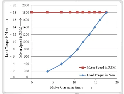
Figure-16. Experimental graph of load torque changes and speed variations with motor current for the reference
speed r=1800 rpm and load changes up to 100% load using FNC.
[image:9.612.74.298.510.677.2]r=1800 rpm and load variations up to 100% load using FNC. From the Figurer-16 it is observed that the motor speed is regulated. The FNC maintain the speed as rated value even if the load torques changes. The motor current is also within the limit of the reference value. Moreover
the speed-current and torque-current curves almost follow the DC series motor characteristics. The Table-6 exposes the performance comparison of hardware of proposed system with Fuzzy logic controller.
Table-6. Hardware Performance Comparison of proposed system with conventional PID controller for the speed r=1800 rpm and TL=10%.
Controller Fuzzy controller FNC
Simulation Hardware Simulation Hardware
Settling time in sec. 1 6 0.94 4.5
Max. over Shoot in % 0.36 Nil Nil Nil
Steady State Error ±5 ±15 Nil ±2
7. CONCLUSIONS
In this work the performance of Hybrid Fuzzy-Neuro controlled DC-DC converter fed DC series motor was presented. The dynamic speed response of DC series motor with FLC and FNC was estimated for different load torque and different set speed change. It was found that the speed can be controlled effectively with hybrid FNC. The hybrid FNC reduced the peak overshoot, settling time and steady state error of the DC series motors. The number of neurons used in each layer and the number of layers are reduced in the designed hybrid FNC. There by the trained hybrid FNC requires less computation time and reduced the complexity of the controller design than the classical PI and FLC. It was implemented with a simple low cost NXP 80C51 microcontroller (P89V51RD2BN) based embedded system, thus the cost of the system also reduced. The analysis provides the various useful parameters and the information for effective use of developed system.
REFERENCES
[1] Philip. T.Krein. 1998. Elements of power Electronics, Oxford University Press.
[2] Dimiter Drainkov, Hans Hellendoorn and Michael Reinfrank. 1996. An Introduction to Fuzzy Control, Narosa Publishing House.
[3] Zurada J. M. 1992. Introduction to Artificial Neural Systems, Mumbai: Jaico Publishing House.
[4] MATLAB, Neural Network Tool Box User’s Guide, Version 3, Massachusetts: The Mathworks Inc.
[5] H. A. Yousef, H. M. Khalil. 1995. A fuzzy logic-based control of series DC motor drives. Proceedings
of the IEEE International Symposium on. 2(10-14): 517-522.
[6] M Madheswaran and M Muruganandam. 2012. Simulation and Implementation of PID-ANN Controller for Chopper Fed Embedded PMDC Motor. Journal on Soft Computing. 2(3): 319-324.
[7] M.Muruganandam and M. Madheswaran. 2009. Performance Analysis of Fuzzy Logic Controller Based DC-DC Converter fed DC Series Motor. IEEE international conference, Chinese Control and Decision Conference (CCDC 2009). pp. 1635-1640.
[8] M.Muruganandam and M.Madheswaran, 2009. Modeling and Simulation of Modified Fuzzy Logic Controller for Various types of DC motor Drives. IEEE international conference on Control, Automation, Communication and Energy Conservation -2009, 4th-6th.
[9] M Muruganandam and M Madheswaran. 2013. Stability analysis and implementation of chopper fed DC series motor with hybrid PID-ANN controller. International Journal of Control, Automation and Systems. 1(5): 966-975.
[10]M. Muruganandam and M. Madheswaran. 2012. Experimental verification of chopper fed DC series motor with ANN controller. Frontiers of Electrical and Electronic Engineering. 7(4): 477-489.
Volume 3, 2-6 November. 3: 3184-3189. Digital Object Identifiers 10.1109/IECON.2004.1432322.
[12]Buja G. S. and Todesco F. 1994. Neural network implementation of a fuzzy logic controller. IEEE Trans. Indust. Electron. 41(6): 663-665.
[13]Ahmed Rubaai, Raj Kotaru. 2000. Online Identification and Control of a DC Motor Using Learning Adaptation of Neural Networks. IEEE Transaction on Industry applications. 36(3): 935-942.
[14]Boumediene Allaoua, Abdellah Laoufi, Brahim Gasbaoui and Abdessalam Abderrahmani. 2009. Neuro-Fuzzy DC Motor Speed Control Using Particle Swarm Optimization. Leonardo Electronic Journal of Practices and Technologies. (15): 1-18.
[15]Hasan Abbasi Nozari, Hamed Dehghan Banadaki, Mohammad Mokhtare and Somayeh Hekmati Vahed. 2012. Intelligent non-linear modelling of an industrial winding process using recurrent local linear neuro-fuzzy networks. Journal of Zhejiang University-SCIENCE C (Computers and Electronics) Springer-Verlag Berlin Heidelberg. pp. 403-412.
[16]M. Madheswaran and M. Muruganandam. 2012. Simulation and Implementation of PID-ANN Controller for Chopper Fed Embedded PMDC Motor. ICTACT International Journal on Soft Computing. 02(03): 319-324.
[17]Ahmed Rubaai, Marcel J. Castro-Sitiriche, Moses Garuba and Legand Burge. 2007. Implementation of Artificial Neural Network-Based Tracking Controller for High-Performance Stepper Motor Drives. IEEE Transactions on Industrial Electronics. 54(1): 218-227.
[18]Muammer Gokbulut, Besir Dandil and Cafer Bal. 2006. A Hybrid Neuro-Fuzzy Controller for Brushless DC Motors. Springer-Verlag Berlin Heidelberg. pp. 125-132.
[19]Cetin Gencer, Ali Saygin, Ismail Coskun. 2006. DSP Based Fuzzy-Neural Speed Tracking Control of Brushless DC Motor. Springer-Verlag Berlin Heidelberg. pp. 107-116.
[20]M. Ali Akcayol. 2004. Application of adaptive neuro-fuzzy controller for SRM. An International Journal of Advances in Engineering Software, Elsevier. pp. 129-137.
[21]Hamit Erdem. 2011. Application of Neuro-Fuzzy Controller for Sumo Robot control. An International Journal of Expert Systems with Applications, Elsevier. pp. 9752-9760.
[22]S. K. Pradhan, D. R. Parhi and A. K. Panda. 2006. Neuro-fuzzy technique for navigation of multiple mobile robots. Springer Science + Business Media, Fuzzy Optim Decis Making. pp. 255-288.