© 2015, IRJET ISO 9001:2008 Certified Journal
Page 963
A Case Study on Thermodynamic Analysis of Cogeneration Power Plant
1
Darshan H Bhalodia, Atmiya Institute Of Technology And Science For Diploma Studies, Rajkot, Gujarat, India
2
Darshit B Parikh, Atmiya Institute Of Technology And Science For Diploma Studies, Rajkot, Gujarat, India
3
Jignesh B Sinojiya, Atmiya Institute Of Technology And Science For Diploma Studies, Rajkot, Gujarat, India
---***---Abstract -
The aim of this work is to use the energyanalysis based on the first law of thermodynamics to identify the locations and magnitudes of losses in order to maximise the performance of a 25 MW plant at Saukem Ltd., Porbandar to evaluate the overall plant, boiler, and turbine and subsystem efficiencies. Energy flows in a boiler have been shown in this paper. The boiler efficiency is calculated using indirect method after estimating the various heat losses in the boilers. From results the overall thermal efficiency of the plant by computing the individual efficiency of the boiler (79.4%), steam turbine (33.57%), and generator (98%) appears to be 26.2 %.
Key Words:
Energy, Boiler Efficiency, Extraction back-
Pressure Turbine.
I:
I
NTRODUCTIONEnergy is one of the major inputs for the economic development of any country.The overall power scene in India shows heavy shortages in almost all the states. Today, many electrical generating utilities are striving to improve the efficiency (or heat rate) at their existing thermal electric generating stations, many of which are over 25 years old. Often, a heat rate improvement of only a few percent appears desirable as it is thought that the costs and complexity of such measures may be more manageable than more expensive options. To assist in improving the efficiencies of coal-to-electricity technologies, their thermodynamic performances are usually investigated. In general, energy technologies are normally examined using energy analysis. The primary objective of energy efficiency measures in the industry is to lower energy cost by reducing the need for purchased energy or by using least-cost energy resources. Cogeneration, being one of the energy conservation methods, offers good scope, especially in process industries, for attaining higher efficiency levels.[1] The
increased awareness that the world’s energy resources are limited has caused many countries to re-examine their energy policies and take drastic measures in eliminating waste. The first law analysis is used to assess the overall plant performance. It has also sparked interest in the scientific community to take a closer look at the energy conversion devices and to develop new techniques to better utilize the existing limited resources (Cengel and Boles, 2008). Nowadays, there are a few methods to measure the performance of a power plant (Hussein et al., 2001).[2] Thermodynamically, it is established that the thermal efficiency of the plant increases with an increase in the maximum cycle temperature. However, if the maximum cycle temperature increases, the exhaust temperature also increases, thereby increasing the loss of heat to the environment.
II:
WHAT IS COGENERATION?
1) Extraction back-pressure turbine type:
© 2015, IRJET ISO 9001:2008 Certified Journal
Page 964
Fig.1 Different Configurations for Back Pressure SteamTurbines
1) Application:
Cogeneration systems are also quite suitable for various process industries involving rayon, pulp and paper, chemical process, textile and fertilizer, where both power and process steam are used. When a constant amount of heat is required (because of little possibilities of control) Very often there are various steam turbines arranged on a line in order to allow using one or more turbines according to the requirements.[3]
2) Extraction condensing turbine:
The functionality is similar to that of a cycle with back pressure turbine with the difference that here the extraction steam for heat generation is not taken from the rear part but from the middle part of the turbine. This has the advantage that heat and power generation can be adjusted to the different equipments. With the help of valves the extraction pressure can be adjusted right at the extraction point so that the required steam conditions for heat generation can also be kept when run at part load. This is the advantage over the topping steam turbine where the conditions vary according to the load point. [ 5]
III: DESCRIPTION OF COGENERATION POWER
PLANT
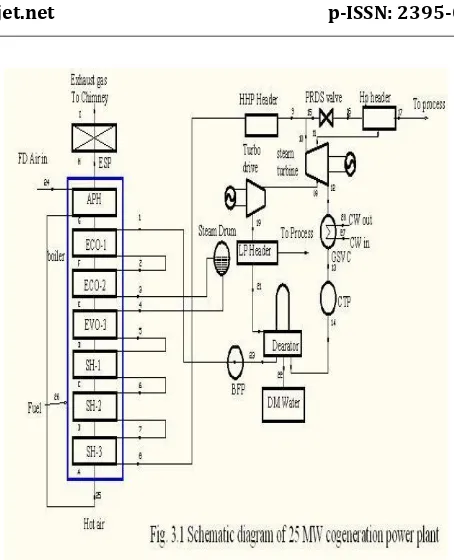
The Steam turbine cogeneration plant, chosen for the present study consists of two steam turbine units total 25 MW power output and two CFBC boiler with capacity of 120 TPH steam flow rate each one. Fig.1 shows the schematic layout of the plant. Each ST unit has an installed capacity of 12.5 MW and each boiler unit has the capacity
to generate process heat as 120 TPH of HP steam at 105 kg/cm2 and 90 TPH ofLP steam at 31.5 kg/cm2.[ 9]
1) Plant operation:
[image:2.595.39.251.77.261.2] [image:2.595.301.563.479.764.2]A schematic diagram of the plant with its various significant components, considered for the present study is shown in Fig.1 The demineralized water from the DM tank enters the boiler drum using boiler feed pumps. This DM water then passes through the bank tubes where it is converted into steam and flows through the turbine on reaching to the desire temperature and pressure. The water is converted into steam using the heat energy of the fuel used in combustion process. Lignite coal used as a fuel. After combustion of fuel, gases are generated which after exchanging heat through the water wall tube escapes from the stack. The steam after passing through the turbine goes to extraction and last to the exhausted to process industry. The process is repeated again wherein, the condensed steam is sent back to the upper drum using feed water pumps. The turbine rotates using the steam and the generator is connected through gear box rotates which in turn leads to generation of electricity. This electricity is then transmitted through the transmission lines. The steam extracted from the various points is also shown in the schematic diagram. [9]
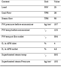
Table 1 Working Data of 25MW Cogeneration Power Plant
Content Unit Value
Load MW 25
Coal Flow TPH 28
Steam flow TPH 90
FW pressure before economiser kg/cm2 107
FW temp before economiser
c
125FW temp at Eco outlet
c
306O2 in APH inlet % 4
O2 in APH outlet % 4.5
Superheated steam temp
c
505© 2015, IRJET ISO 9001:2008 Certified Journal
Page 965
CO2 in flue gas % 14
CO in flue gas % 0.6
FW flow TPH 95
LP steam to dearetor temp
c
133Temperature of water at dearator outlet
c
123Flue gas inlet to APH
c
144Flue gas at stack
c
102Flue gas inlet to economizer
c
320Flue gas at outlet of super heater
c
667 [image:3.595.306.533.65.345.2]Hot air from APH
c
220Table 2 Coal specifications
Parameters Kutch Lignite
coal
Imported coal
GCV (kcal/kg) 3380 6200
Ash content (%) 10.8 10
Moisture (%) 34 13.27
Sulphur content (%) 2.5 0.4
Oxygen (%) 12.5 8.2
Carbon (%) 36.5 62.5
Hydrogen (%) 2.5 4.39
Fig.2 Schematic diagram of 25MW cogeneration plant
IV:
E
NERGY ANALYSISThe first law of thermodynamics (Energy analysis) deals with the quantity of energy and asserts that energy cannot be created or destroyed. The law merely serves as a necessary tool for the bookkeeping of energy during a process and offers no challenges to the engineer (Ganapathy et al., 2009; Makinde, 2008; Cengel and Boles, 2008). Energy is always conserved (in balance); it can neither be produced nor consumed. Energy is a measure of quantity (Dincer and Al-M uslim, 2001). The First Law deals with the
[image:3.595.28.286.387.606.2]© 2015, IRJET ISO 9001:2008 Certified Journal
Page 966
that for conservation of energy it is necessary to pursuetwo objectives, namely to reduce the demand for energy and to supply this demand at the maximum possible efficiency. The second objective is within the field of the engineering community. The first law efficiency of a thermal system, which is the ratio of the work output to the heat input, has shortcomings. [4]
For example: It cannot be readily generalized to complex systems in which the desired output is a combination of work and heat, as in total energy systems. It completely ignores the exergy concept which plays the central role in governing utilization and conservation of fuel resources. It does not provide any suitable guidance for fuel loss minimization and thus leads to wrong conclusions in terms of fuel economy [6].
V: RESULT AND DISCUSSION
The data for boiler operation and turbine operation of TPS at full load were observed and relevant parameters have been estimated. Using these data and compiled value, First law analysis (energy analysis) is carried out for the given plant. The performance of a plant is evaluated by calculating the overall efficiency of unit by using the individual efficiencies of boiler, turbine and generator. The performance of a plant is evaluated by calculating the individual efficiencies of the boiler, turbine and generator. The efficiency of the boiler is evaluated by indirect method. In the indirect method the input is assumed to be 100% and the various losses encountered in the boiler are calculated and subtracted from 100. The various losses in the boiler are; energy losses due to exhaust gas, energy losses due to hydrogen in fuel, energy losses due to moisture in fuel, energy losses due to moisture coming with air supplied, energy losses due to partial conversion of C to CO, energy losses due to unburnt in fly ash & bottom ash, and radiation, convection. [7] Based on the data available in Table 1, the calculations are made for boiler losses and the results are shown in Table 4. From the available data for the turbine, following calculations are made to calculate the turbine efficiency. Turbine inlet steam flow = 90 TPH = 25 kg/s.
Heat Input to Turbine m
25 3379.7 516.31 1.11 2734 139.16
71584 2880.27
74464.27 /
Power generation heat input to turbine
25 1000
74464.27
33.57%
Overall thermal efficiency=b
h hFW m h hFW
S S DS inlet
KJ kg
T
oilere fficiency×turbine efficiency×generator efficiency
79.4 33.57 98
26.12%
o
Table 3 Different efficiencies of power plant
Sr no Component Efficiency (%)
1 Boiler 79.4
2 Turbine 33.5
3 Generator 98
[image:4.595.302.556.545.775.2]4 Overall efficiency 26.12
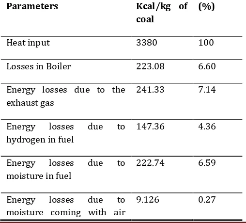
Table 4 Summary of Heat Balance for Coal Fired Boiler
Parameters Kcal/kg of
coal
(%)
Heat input 3380 100
Losses in Boiler 223.08 6.60
Energy losses due to the exhaust gas
241.33 7.14
Energy losses due to
hydrogen in fuel
147.36 4.36
Energy losses due to
moisture in fuel
222.74 6.59
Energy losses due to
moisture coming with air
© 2015, IRJET ISO 9001:2008 Certified Journal
Page 967
suppliedEnergy losses due to partial conversion of C to CO
59.48 1.76
Energy losses due to radiation & convection
67.6 2
Energy losses due to unburnt in fly ash
4.90 0.145
Energy losses due to unburnt in bottom ash
7.77 0.23
Total losses 79.499
VI:
C
ONCLUSIONFrom the above experiment & result analysis it is very clear that CFBC boiler efficiency is highest, which is 79.4% and the heat losses are only 20.6%. Out of all the boiler losses, the highest heat losses 7.14% occurs due to the exhaust gas.
The turbine efficiency is very less and is estimated as 33.57% Because of the several turbine losses like; Losses in regulating valve, Nozzle friction losses, Blade friction losses , Disc friction losses , Partial admission losses , Gland leakage losses, Cary over losses.
From the thermodynamic analysis using first law of thermodynamics, it can be concluded that, energy analysis evaluates the plant quantitatively. The power plant overall efficiency is 26.2%.
VII: FUTURE WORK
In the future work performance analysis will be carried out at Saukem Ltd, Porbandar using plant operational data to evaluate the energy, exergy efficiency of plant, along with heat loss and exergy loss occurs in each component of plant. For that mass flow rate, pressure and temperature of each component are considered for the performance analysis of lignite coal based 25 MW cogeneration power plant.
VIII: ACKNOWLEDGMENTS
We are very much thankful to peoples of Nirma cogeneration power plant for providing sufficient data for plant. We are also thankful to those who help directly or indirectly to complete the project
REFRENCES
[1]T.Ganapathy, N.Alagumurthi, R.P. Gakkhar, Exergy Analysis Of Operating Lignite Fired Thermal Power Plant, Journal Of Engineering Science And Technology Review 2(1) ,123-130,[ 2009].
[2]R.K.Kapooria, S.Kumar, K.S. Kasana,, “An Analysis Of A Thermal Power Plant Working On A Rankine Cycle A Theoretical Investigation”, Journal Of Energy In Sourthen Africa, Vol 19(1), February [2008], 77-82.
[3]Nag, P. K., “Power Plant Engineering,”, Tata McGraw Hill, New Delhi, 2nd Edition, [2001].
[4] El-Wakil, M. M., “New Power Plant Technology”, New York, McGraw-Hill, [1984].
[5] Çengel, Y.A.andA.B.Michael, “Thermodynamics
AnEngineering Approach.”, McGraw Hill Companies, Inc., New York, 6th Edition [2005 ].
[6] C. Mborah, “On the Energy and Exergy Analysis of a 500 KW Steam Power Plant at Benso Oil Palm Plantation”, Research journal of Environmental and Earth Sciences 2(4): 239-244, [2010].
[7]Prof. Alpesh V. Mehta, “Thermodynamic Analysis of Gandhinagar thermal power station”, International Journal of Advanced Engineering Technology, E-ISSN 0976-3945, December [2010].
[8] “Energy efficiency in thermal utilities”, Bureau of Energy Efficiency, Vol 2 pp 155-169 [2007].