© 2015, IRJET ISO 9001:2008 Certified Journal
Page
1219
Analysation of Computer Network Models
P.Bhagya Sree
1, P.S.S. Mounica
2, P.V.Chaithanya
3, P.Teja Sree
41 2 3 4
B.Tech Final Year, CSE, Dadi Institute of Engineering & Technology ,Andhra Pradesh,INDIA
---***---Abstract -
As the computer technology grows, computer network continues to expand the scope of application with more and more users. Computer networks are a system of interconnected computers for the purpose of sharing digital information. In this paper we discuss about types of networks, OSI model and TCP/IP model.Key Words:
Computer Networks, OSI,TCP/IP protocol,
LAN,WAN,MAN.
1. INTRODUCTION
In our present life networks has changed the way of doing business and the way we live, why to wait for days or weeks in order to receive the reply when any information can be available within few seconds because of networks. Networks has developed in such a way that most of the businesses today rely on computer networks and internetworks[2]. But before we ask how quickly we can get hooked up, we need to know how networks operate, what type of technologies available.
A network is a set of devices (often referred to as nodes) connected by communication links. A node can be a computer, printer, or any other device capable of sending and receiving data generated by other nodes on the network. A computer network or data network is a telecommunications network which allows computers to exchange data[3]. Computer networks differ in the transmission media used to carry their signals, the communication protocols to organize network traffic, the network size, topology and organizational internet.
1.1. NETWORK MODELS
The International standard organisation is a multinational body dedicated to WorldWide agreement on International Standards which is used to certify the quality.
These ISO standarads agree or approved the OSI model for proper network communication[7].
The open system interconnectivity is a set of protocols that allows any two different systems irrespective of their architectures
The purpose of OSI model is to show the communication between different devices without changing hardware and software.
OSI model consists of 7 layers[2,3]. They are
Physical layer
Datalink layer
Network layer
Transport layer
Session layer
Presentation layer
Application layer
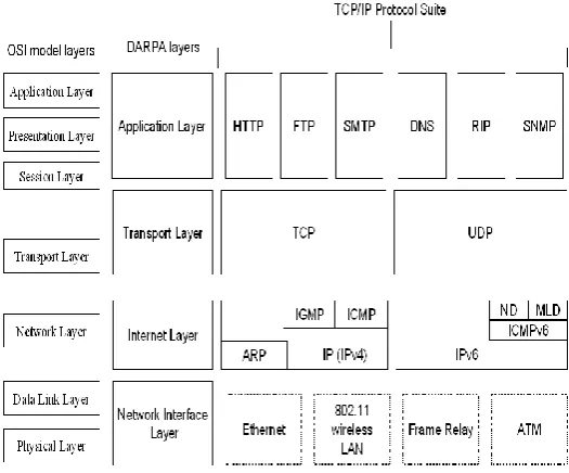
The extension of this OSI model is TCP/IP Protocol suite
Fig -1: TCP/IP Protocol Suite
LAYERS OF TCP/IP PROTOCOL
1. Host to network layer 2. Internet layer
[image:1.595.308.571.437.655.2]© 2015, IRJET ISO 9001:2008 Certified Journal
Page
1220
1. Host to network layer:It includes both the physical layer and the data link layers. At this layer Tcp/Ip does not define any protocols but it specifies by International Standards Organisation
2. Internet layer:
At this layer the Tcp/Ip supports networking protocols(IP) and IP uses four supporting protocols .They are:
1. Address resolution protocol(ARP):
It is used to associate a logical address with a physical address. ARP is used to find the physical address of the node when its logical address is known.
2. Reverse address resolution protocol(RARP)
It allows a post to discover the logical address when its knows . RARP is used when a computer is connected to the network for the first time.
3. Internet message protocol(ICMP)control
It is the mechanism used by the host to send the notification of the problem back to the sender in the transmission of messages through internet.
4. Internet group message protocol(1GMP)
It is used to facilitate the transmission of a message to a group of users.
3. Transport layer
In transport layer three main protocols. The TCP and UDP are responsible for the delivery of message from one process to another process.
1. TCP(Transmission control protocol)
This is the unreliable connection oriented protocol in which connection must be established between both the ends of the transmission data is delivered and the connection is terminated.
2. UDP(User Datagram Protocol)
It is the simpler protocol it is a connectionless unreliable protocol which does not guarantee a proper delivery of message.
3. SCTP(Stream control Transmission Protocol) It provides support for the application for combining the best features of the TCP/UDP.
4. Application layer
The TCP/IP protocol suit is equivalent to the combined features session, presentation and application layer of the OSI model which includes the following protocols[8]
1. SMTP(Simple Mail Transfer Protocol) 2. FTP(File Transfer Protocol)
3. HTTP(Hyper Text Transfer Protocol) 4. DNS(Domain Name Services)
5. SNMP(Simple Network Managing Protocol)
6.
TELNET Protocol2. CATEGORIES OF NETWORKS :
When we speak of networks, we are generally referring to area networks (WAN).The category into which a network falls is determined by its size. A LAN normally covers an area less than 2mi;a WAN can be worldwide. Networks of a size in between are normally referred to as metropolitan area networks and span tens of miles.
2.1. LOCAL AREA NETWORK:
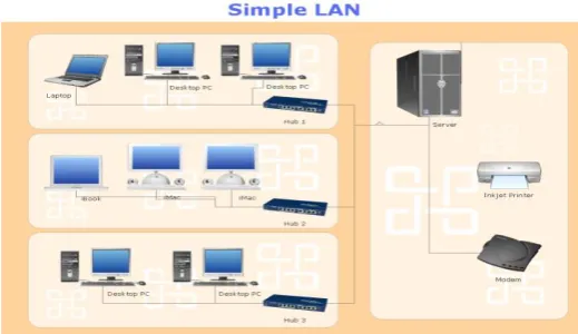
A LAN is usually privately owned and links the devices in a single offices, buildings or campus. LANs are designed to allow resources to be shared between personal computers or workstations. The resources to be shared include hardware (e.g.,a printer),software(e.g., an application program),or data. One of the computers may be given large capacity disk drive and may become server to many clients. software can be stored on this central server and used as needed by the whole group[1].
Fig -2: Local Area Network
[image:2.595.308.568.535.685.2]© 2015, IRJET ISO 9001:2008 Certified Journal
Page
1221
and star. Early LANs had rates in the range 4 to 16megabits per second(Mbps).Wireless LANs are normally 100 or 1000 Mbps. Wireless LANs are the newest evolution in LAN technology[8].
Technical Aspects:
Data link layer and physical layer uses a wide variety of LAN topologies[6].
Most commonly used LAN topology is “switched Ethernet”.
Spanning tree protocols are used to prevent loops.
It includes a variety of network devices such as switches, routers, firewalls etc.
Simple LANs consists of one or more switches which can be connected to router, cable modem or ADSL modem for internet access[3].
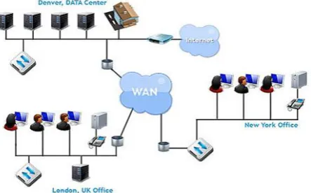
WIDE AREA NETWORK (WAN): A wide area
network(WAN) provides long_ distance transmission of data, image, audio and video information over large geographic areas that comprise a country, a continent or even the whole world. A WAN can be as complex as the backbones that connect the internet or as simple as a dial _up line that connects a home computer to internet.
The switched WAN connects the end systems, which usually comprise a router that connects to another LAN or WAN. The point _to_ point WAN is normally a line leased from a telephone or cable TV provider that connects a home computer or a small LAN to an internet service provider(ISP).
Fig -3: Wide Area Network
An early example of a switched WAN is X.25, a network designed to provide connectivity between end users, which is gradually being replaced by high_ speed, more
efficient network called ‘Frame Relay’. Another example is the asynchronous transfer mode(ATM) network.
METROPOLITAN AREA NETWORK (MAN):
A metropolitan area network (MAN) is a network with a size between a LAN or WAN which normally covers the area inside a town or a city. It is designed for customers who need a high _speed connectivity to the internet[2].
Fig -4: Metropolitan Area Network
An example of a MAN is the part of the telephone company
network that can provide a high speed DSL line to the
customer. MAN links between local area networks have
been built with wireless links using either microwave,
radio, or infra-red laser transmission. Most companies
rent or lease circuits from common carriers because laying
long stretches of cable is expensive.
3. PHYSICAL STRUCTURE
We know that a network is a connection of two or more devices through links, the connection of devices through links can be possible in two ways, there as follows
Point to point connection:
A point_ to_ point connection provides a dedicated link
between the devices. Most point to point connections use
an actual length of wire or cable to connect the ends,but
other options such as microwave or satellite links are also
[image:3.595.310.553.245.350.2] [image:3.595.60.282.548.686.2]© 2015, IRJET ISO 9001:2008 Certified Journal
Page
1222
Multipoint connection:
A multipoint connection is one in which more than two specific devices share a single link. In a multipoint environment, the capacity of the channel is shared spatially or temporally. The connection of two or more devices either by point _ to_ point connection or multipoint connection through links is called ”topology”[2].
4. TOPOLOGY
The topology of a network is the geometric representation of the geometric relationship of all the links and linking devices (usually called nodes) to one another. There are four basic topologies possible mesh, star, bus and ring. They are as follows[5].
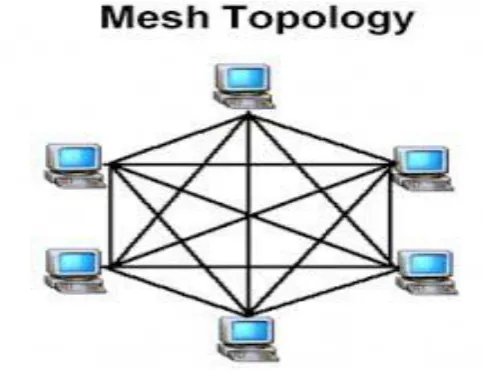
1) MESH Topology:
In a mesh topology,every device has a dedicated point-to-point link to every other device.
The term dedicated means that the link carries traffic only between the device it connects.
It offers several advantages over other network topologies.
A mesh topology is a robust.
Fig -5: Mesh Topology
2) STAR Topology
In this each device has a dedicated point-to-point link only to a central controller, usually called a “hub”. Unlike a mesh topology, a star topology doesn’t allow direct traffic
between devices. The controller acts as an exchange, if one device wants to send data to another, It sends it to controller, which relays data to other connected devices. It less expensive compared to mesh. If one link fails, only that link is affected. It requires less cable.
Fig -6: Mesh Topology
3) BUS Topology:
A bus topology is a multipoint connection. It consists of a long cable which acts as a backbone to link all devices in a network. Nodes are connected to the cable by drop lines and taps. A drop line is a connection running between the device and the main cable.
A tap is a connector that splices into the main cable to create a contact with metallic core. As the signal travels through it energy is converted into heat which makes it weaker as it travels further. It includes ease of installation. It is difficult to reconnect and fault isolation[2].
[image:4.595.309.558.202.374.2] [image:4.595.39.281.464.652.2] [image:4.595.309.555.552.747.2]© 2015, IRJET ISO 9001:2008 Certified Journal
Page
1223
4) RING Topology:A ring is relatively easy to install and reconfigure. Each device linked to only its immediate neighbors. The only constraints are media and traffic considerations[3]. If one device doesn’t receive a signal within a specified period then it issues an alarm. Unidirectional is the disadvantage. A break in the ring can disable the network. Weakness can be solved by using a dual ring or a switch capable of closing off the break.
Fig -8: Ring Topology
5.CONCLUSIONS
With the rapid development of computer technology, computer network continues to expand the scope of application with more and more users. This paper gives an overview of basic concepts related to network design and specific models.
REFERENCES
[1] Xiao Ze. Research on computer network security analysis model [J]. Journal On Communications, 2012(3):269.
[2] Computer Networks-william Stallings
[3] Data Communication & Networking - Behrouz A Forouzan
[4] Cui Jing, Liu Guangzhong, the basics of computer network [J]. Tsinghua University Press, 2010.07.01. [5] On the understanding of computer network
protocols- Anders Berglund.
[6] Mathematical Foundations of computer Networking by keshav
[7] Computer Networking: Principles, Protocols and practice. Olivier Bonaventure.http://inl.info.ucl.ac.be
[8] Analysis and research of Computer Network Security -Jie Shan ,Binzhou Polytechnic, Binzhou, Shandong, China.
BIOGRAPHIES
P. Bhagya Sree is a final year student of Computer Science & Engineering branch in Dadi Institute of Engineering & Technology.
P.S.S.Mounika is a final year student of Computer Science & Engineering branch in Dadi Institute of Engineering & Technology.
P. Teja Sree is a final year student of Computer Science & Engineering branch in Dadi Institute of Engineering & Technology.
[image:5.595.35.283.262.404.2]