http://dx.doi.org/10.4236/mme.2014.43014
A Study on the Dynamic Behavior of
Wheel-Type Train Propelled by
Superconducting Linear Synchronous Motor
Jinho Lee, Changyoung Lee, Jeongmin Jo, Yongjae HanMaglev Train Research Team, Korea Railroad Research Institute, Uiwang-si, Republic of Korea Email: [email protected], [email protected], [email protected], [email protected]
Received 27 June 2014; revised 26 July 2014; accepted 6 August 2014 Copyright © 2014 by authors and Scientific Research Publishing Inc.
This work is licensed under the Creative Commons Attribution International License (CC BY). http://creativecommons.org/licenses/by/4.0/
Abstract
This paper deals with a study on the dynamic behavior of 600 km/h wheel-type train propelled by superconducting linear synchronous motor (LSM). This train is of a traditional wheel-on-rail type with traction motors on wheel-bogies. However, for the 600 km/h speed, on the both sides of each vehicle, superconducting LSMs are attached and the ground coils are installed on the guideway. In this case, the guideway irregularities act as disturbance to the vehicle causing deterioration of ride comfort. And besides thrust force, the normal force could be created in superconducting LSM control, which influences vehicle dynamics during running. In this study, to examine the effect of guideway irregularity and normal force on dynamic behavior of proposed train, the vehicle dy-namic model is driven and frequency analysis is performed through simulation. The simulation results show that the lateral directional acceleration is mainly influential to ride comfort; however this could be reduced effectively by electromagnetic damping force from linear generator. It is al-so shown that the normal force effect from superconducting LSM control is limited even though the attractive normal force acts favorably to ride comfort.
Keywords
High Speed Railway, Superconducting Linear Synchronous Motor, Dynamic Behavior
1. Introduction
alterna-tive for high speed rail transportation, the maglev using linear synchronous motor (LSM) is also being commer-cialized in Shanghai China with 430 km/h as maximum speed [1]. And Japan has built a construction plan of Tokyo-Nagoya route by maglev until 2027 and conducted the performance test in 42.8 km test line [2] [3].
Despite the superiority in high speed, the drawback such as interoperability problem that maglev could not interoperated with the existing wheel-on-rail track is the main obstacle for maglev commercialization [4]. To resolve this problem while aiming at the high speed, compared with the 300 km/h level wheel type railway and 400 km/h level maglev, the new concept of high speed railway aiming at 600 km/h level is recently introduced by C. Y. Lee [5]. In [5], author proposed the dual-mode propulsion system propelled by traction motors in low speed and superconducting LSM in high speed. As shown in Figure 1, by adopting the traditional wheel type rail, the interoperability problem with existing railroad could be resolved and by installing superconducting electromagnets on vehicle sides and ground LSM coils on the exclusive high speed line, the powerful thrust force could be achieved.
In superconducting LSM propulsion, since the thrust force is produced from interactive force between elec-tromagnets on vehicle and LSM coils on guideway, the irregularities of guideway cause deterioration of ride comfort [6]. Since the precise construction of guideway requires excessive amount of cost, active vibration con-trol based on vehicle dynamic analysis should be considered to improve the ride comfort. And in superconduct-ing LSM propulsion control, the normal directional force in respect of thrust direction could be created by ad-justing the magnetic field angle [5], so the normal force effect on the vehicle dynamic behavior is also needed to be analyzed.
In this study, as a model for dynamic analysis, the Korea high speed wheel type train (KTX) attaching super-conducting electromagnets on vehicle sides is assumed. Based on the proposed model, the computation model and mathematical equations including external disturbance are established. Then, through the simulations, sys-tem dynamic behavior according to the guideway irregularities and normal forces is analyzed and the ride com-fort improvement method is suggested.
2. Vehicle Dynamic Model
2.1. Configuration of Proposed Vehicle Model
The configuration of vehicle model for dynamic analysis is shown in Figure 2. The forehead motor car of KTX with two wheel bogies is adopted as main body and it is assumed that superconducting electromagnets are at-tached on sides without shape modification of main body. Therefore, the major vehicle characteristics are de-termined by wheel-bogies whose detail components are described in Figure 3 [7]. Based on this, the vehicle dynamic model for vertical, lateral and rolling direction could be established like Figure 4. The descriptions of symbols in this model are as follows:
1
m, m2: masses of bogie and car body 1
I , I2: moment of inertial of bogie and car body
py
k , kpz: spring constants of bogie in lateral and vertical direction
sy
k , ksz: spring constants of car body in lateral and vertical direction
py
c , cpz: damping constants of bogie in lateral and vertical direction
sy
c , csz: damping constants of car body in lateral and vertical direction
0
k
h , hk1, hk2: lateral spring attachment height
1
c
h , hc1, hc2: lateral damper attachment height
1
k
b , bk2: half of the lateral distance between vertical springs
1
c
b , bc2: half of the lateral distance between vertical dampers
1
y , y2: lateral displacement 1
∅ , ∅2: rolling angular displacement
1
z , z2: vertical displacement 0
y , z0: guideway irregularity of lateral and vertical direction
Figure 1. Concept of high speed railway with dual-mode pro- pulsion system [5].
Figure 2. Configuration of proposed vehicle.
Figure 4. Dynamic model of proposed vehicle.
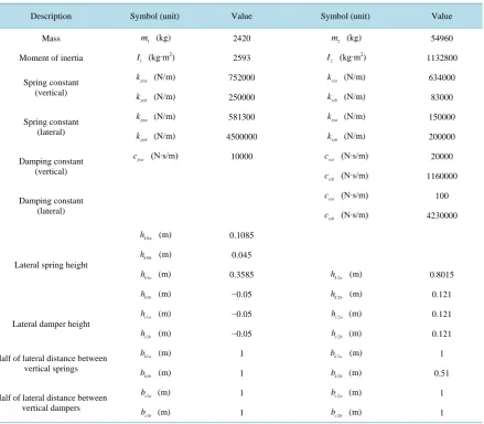
Table 1. Characteristic values of dynamic model [7].
Description Symbol (unit) Value Symbol (unit) Value
Mass m1 (kg) 2420 m2 (kg) 54960
Moment of inertia I1 (kg∙m
2)
2593 I2 (kg∙m
2)
1132800
Spring constant (vertical)
pza
k (N/m) 752000 ksza (N/m) 634000
pzb
k (N/m) 250000 kszb (N/m) 83000
Spring constant (lateral)
pya
k (N/m) 581300 ksya (N/m) 150000
pyb
k (N/m) 4500000 ksyb (N/m) 200000
Damping constant (vertical)
pza
c (N∙s/m) 10000 csza (N∙s/m) 20000
szb
c (N∙s/m) 1160000
Damping constant (lateral)
sya
c (N∙s/m) 100
syb
c (N∙s/m) 4230000
Lateral spring height
0 k a
h (m) 0.1085
0
k b
h (m) 0.045
1 k a
h (m) 0.3585 hk a2 (m) 0.8015
1
k b
h (m) −0.05 hk b2 (m) 0.121
Lateral damper height
1 c a
h (m) −0.05 hc a2 (m) 0.121
1
c b
h (m) −0.05 hc b2 (m) 0.121
Half of lateral distance between vertical springs
1 k a
b (m) 1 bk a2 (m) 1
1
k b
b (m) 1 bk b2 (m) 0.51
Half of lateral distance between vertical dampers
1 c a
b (m) 1 bc a2 (m) 1
1
c b
[image:4.595.100.540.331.715.2]ponents with same function.
2.2. Dynamic Equation for Vertical Direction
Based on the dynamic model achieved previously, the dynamic equations for vertical direction could be ex-pressed as follows:
Bogie vertical motion
(
)
(
)
(
)
(
)
(
)
1 1 1 2 1 2
0 0
pza sza szb sza szb pza pzb sza szb sza szb
pz pza pzb
m z c c c z c c z k k k k z k k z
c z k k z
+ + + − + + + + + − +
= + +
(1)
Car body vertical motion
(
)
(
)
(
)
(
)
2 2 sza szb 1 sza szb 2 sza szb 1 sza szb 2 0
m z − c +c z + c +c z − k +k z + k +k z = (2)
If we set the state variable like
[
]
T1, 1, 2, 2
z z z z
=
x (3)
and the state space equation like
0
x=Ax+Bz , (4)
then, the system matrix A could be expressed like
(
)
(
)
(
)
(
)
(
)
(
) (
)
1 1 1 1 2 2 2 20 1 0 0
1 0
0 0
sza
pza pzb sza szb pza sza sza szb
sza szb
sza szb
sza szb sza szb
c
k k k k c c k k
m m
m m
c c
k k
k k c c
m m m m + + + + + − − = + + + + − −
A (5)
And the external input term, Bz0 can be express like
(
)
0 0
0 1 1
0
0
0 pza pzb
pza k k
c
z z
z m m
+ + =
B . (6)
If input is sinusoidal such as z0 =Hsin
( )
ωt , the second element in Equation (6) can be re-expressed as fol-lows:(
)
( )
(
)
( )
(
)
0 0
1 1 1 1
cos sin Ωsin
pza pzb pza pzb
pza k k pza k k
c c
z z H t H t t
m m m ω ω m ω ω α
+ +
+ = + = −
(7)
where
( ) (
2)
2 11
Ω pza pza pzb , tan pza pzb
pza
k k
H
c k k
m α c
− +
= + + = −
.
Then, Equation (6) can be simplified like
(
)
0 0 1 Ωsin 0 0z ω αt
= −
2.3. Dynamic Equation for Lateral and Rolling Direction
To achieve the dynamic equations for lateral and rolling direction of proposed system, the similar procedure to previous section could be applied. However, in this case, since the energy balanced equation about momentum should be constructed, the distance between components position and mass center described in Table 1 should be considered. And it is assumed that the lateral disturbance, y0 originated from guideway irregularity acts on
the mass center of bogie for simplicity. The dynamic equation for lateral and rolling direction could be ex-pressed as follows:
Bogie lateral motion
(
)
(
)
(
)
(
)
(
)
(
)
(
)
(
)
(
)
(
)
(
)
1 1 1 1 2 1 2 1
0 0 1 0 1 2 2 1 1
2 2 1 1 2 2 1 1 2 2 1 1
0
pya pyb py sya syb sya syb
pya k a pyb k b py c sya k a k a
syb k b k b sya c a c a syb c b c b
pya pyb sya syb
m y k k y c y k k y y c c y y
k h k h c h k h h
k h h c h h c h h
k k k k y
+ + + − + − − + − + + ∅ + ∅ − ∅ + ∅ − ∅ + ∅ − ∅ + ∅ − ∅ + ∅ = + + +
(9)
Car body lateral motion
(
)
(
)
(
)
(
)
(
)
(
)
(
)
(
)
2 2 2 1 2 1 2 2 1 1 2 2 1 1
2 2 1 1 2 2 1 1
0
sya syb sya syb sya k a k a syb k b k b
sya c a c a syb c b c b
m y k k y y c c y y k h h k h h
c h h c h h
+ + − + + − + ∅ + ∅ + ∅ + ∅
+ ∅ + ∅ + ∅ + ∅ =
(10)
Bogie rolling motion
(
)
(
)
(
)
(
)
(
)
(
)
(
)
(
)
(
)
1 1 0 0 1 1 1 1 2 1 1 1 2 1
2 2 2
0 0 1 1 2 2 1 1 1 2 2 1 1
1 2 2 2 1 1 2
pya k a pyb k b py co sya k a syb k b sya c a syb c b
pya k a pyb k b py co sya k a k a k a syb k b k b k b
sya c a c a c b syb c b c
I k h k h y c h y k h k h y y c h c h y y
k b k b c h k h h h k h h h
c h h h c h h
∅ + + + + + − + + − + + ∅ + ∅ + ∅ + ∅ + ∅ + ∅ + ∅ + ∅ +
(
)
(
)
(
)
(
)
(
)
(
)
(
)
2 2 2 2
2 1 1 1 1 1 1 1 1
2 2 2 2 2 2 2 2
2 2 2 1 2 2 2 1 2 2 2 1 2 2 2 1
0
b c b pza k a pzb k b pza c a pzb c b
sza k a k a szb k b k b sza c a c a szb c b c b
h k b k b c b c b
k b b k b b c b b c b b
∅ + ∅ + + ∅ + + ∅ − ∅ − ∅ − ∅ − ∅ − ∅ − ∅ − ∅ − ∅ = (11)
Car body rolling motion
(
)
(
)
(
)
(
)
(
)
(
)
(
)
(
)
(
)
(
)
2 2 2 2 2 1 2 21 2 1 2 2 2 1 1
2 2
2 2 2 1 1 2 2 2 1 1 2 2 2 1 1 2 2 2 1
2 2
2 2 2 1 2
sya k a syb k b sya c a syb c b sya k a k a k a
syb k b k b k b sya c a c a c a syb c b c b c b sza k a k a
szb k b k b sza c a
I k h k h y y c h c h y y k h h h
k h h h c h h h c h h h k b b
k b b c b
∅ + + − + + − + ∅ + ∅
+ ∅ + ∅ + ∅ + ∅ + ∅ + ∅ + ∅ − ∅
+ ∅ − ∅ +
(
2 2)
(
2 2)
2 bc a2 1 cszb bc b2 2 bc b2 1 0
∅ − ∅ + ∅ − ∅ =
(12)
If we set the state variable like
T 1, 1, 2, 2, 1, 1, 2, 2
y y y y
= ∅ ∅ ∅ ∅
x (13)
and the state space equation like
0
x= Ax+Bz , (14)
then, the elements of matrix A and B could be achieved in a similar way described in previous section.
3. Simulation Results
Based on dynamic equations driven in previous section, the simulation regarding ride comfort by using the fre-quency response analysis in vertical, lateral and rolling direction was performed. For the vertical directional si-mulation, as an input z0, a sine wave with a magnitude 10 mm and 100 m wavelength is used [8]. And as a
lat-eral and rolling direction disturbance input y0, a 1 mm magnitude and 100 m wavelength sine wave is used [6].
In both cases, the travel speed of train is assumed as 500 km/h.
3.1. Ride Comfort Analysis
Figure 5. Frequency response of car body in vertical direction.
at 0.6 Hz is found. According to the [9] which studied about ride comfort of high speed train based on ISO- 2631 (guide for evaluation of human exposure to whole-body vibration), the vibration of frequency range in 4 - 12 Hz for the vertical direction and 0.6 - 2 Hz for the lateral direction are sensitive to human body. Since the vi-bration of frequency for vertical direction is outside of the range 4 - 12 Hz, it seems that the ride comfort for vertical direction couldn’t be a major concern in this case.
The frequency response of car body in lateral and rolling direction is shown in Figure 6. In this case, since the peak values are found at 1.5 Hz in both cases, uncomfortability in lateral direction could be an issue, so, this value is needed to be reduced by further vibration reduction methods.
3.2. Effect of Normal Force
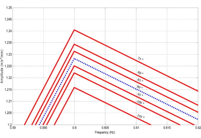
In this section, the effect of normal force produced in superconducting LSM propulsion control is examined. Since the typical relation between thrust and normal force in superconducting LSM control is trigonometrical with respect to the magnetic field angle as shown in Figure 7, the normal force with respect to the angle could be simply calculated [5]. In our case, due to the symmetry form in lateral direction, only vertical directional normal force is considered. By assuming that the maximum thrust force per one car is 46 kN (This value can be achieved at 90˚ of magnetic field angle, [5]) and the slope of lateral guideway is 60˚, the normal forces with
re-spect to the different magnetic field angle (i.e. 75˚, 80˚, 85˚, 90˚, 95˚, 100˚, 105˚) are added in right side of
Equ-ation (1) for simulEqu-ation. As shown in the simulEqu-ation results in Figure 8, it is found that attractive normal force acts favorably to ride comfort while the repulsive force acts unfavorably. However, in both cases, these effects are negligible (i.e. change rates are under 1%) as summarized in Table 2.
3.3. Ride Comfort Improvement Method
As reviewed in Section 3.1, the vibration frequency of lateral direction positioned within the range of 0.6 - 2 Hz is expected to influence ride comfort un-favorably. To mitigate this vibration, the electromagnetic force from the linear generator is considered. The linear generator is usually installed in high speed maglev to generate power in traveling vehicle by using the harmonic magnetic interaction with ground LSM coil. And during linear gene-rator operation, the electromagnetic force is generated additionally from linear genegene-rator and this force could act as damper in primary suspension [10]. On condition that this method is also applicable to our system, the vibra-tion reducvibra-tion effect by electromagnetic force from linear generator is investigated. By assuming that the gener-ated force with maximum value of fm has the switched polarity according to the polarity of lateral velocity
[10], the electromagnetic force can be expressed like:
( )
1m m
F = −sign y ⋅f (15) To examine the effect of this force on the vehicle dynamics, Equation (15) with different value of fm is in-serted in right side of Equations (1) and (9).
0 0.2 0.4 0.6 0.8 1 1.2 0
0.2 0.4 0.6 0.8 1 1.2 1.4 1.6
Frequency (Hz)
A
m
pl
it
ude (
m
/s
Figure 6. Frequency response of car body in lateral and rolling direction.
Figure 7. Typical thrust and normal force as functions of the magnetic field angle [5].
Figure 8. Frequency response of vertical directional car body according to magnetic field angle.
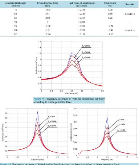
The simulation results about effects of damping force from linear generator results are shown in Figure 9and
Figure 10. As shown in figures, the ride comforts are improved effectively in both cases, and the amount of im-
0 0.5 1 1.5 2 2.5 3
0 0.2 0.4 0.6 0.8 1 1.2 1.4 1.6 1.8 2
Frequency (Hz)
A
m
pl
it
ude (
m
/s
2/mm)
0 0.5 1 1.5 2 2.5 3
0 0.002 0.004 0.006 0.008 0.01 0.012 0.014
Frequency (Hz)
A
m
pl
it
ude (
rad/
s
[image:8.595.138.508.215.658.2] [image:8.595.145.481.427.658.2]Table 2. Normal force effect according to the magnetic field angle in vertical direction.
Magnetic field angle (degree)
Created normal force (kN)
Peak value of acceleration (m/s2/mm)
Change rate
(%) Remarks
75 7.86 1.2405 1.00
Repulsive
80 3.91 1.2343 0.50
85 2.00 1.2313 0.26
90 0 1.2281 - -
95 −2.00 1.2251 −0.24
Attractive
100 −3.91 1.2221 −0.49
105 −7.86 1.2159 −1.00
[image:9.595.88.540.99.637.2]Figure 9. Frequency response of vertical directional car body according to linear generator force.
Figure 10. Frequency response of lateral and rolling directional car body according to linear generator force.
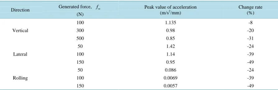
provement is more remarkable in lateral and rolling direction than vertical direction. This result is summarized inTable 3.
4. Conclusion
[image:9.595.94.537.447.631.2]Table 3. Ride comfort improvement according to linear generator force.
Direction Generated force, fm
(N)
Peak value of acceleration
(m/s2/mm) Change rate (%)
Vertical
100 1.135 -8
300 0.98 -20
500 0.85 -31
Lateral
50 1.42 -24
100 1.14 -39
150 0.95 -49
Rolling
50 0.086 -24
100 0.0069 -39
150 0.0057 -49
level high speed, the dynamic model including guideway irregularities is established and numerical simulations are performed. From the frequency response analysis regarding ride comfort, lateral direction is expected to be more influential to ride comfort than vertical direction. And it is shown that the normal force effect on the ver-tical directional vehicle behavior according to the magnetic field angle would be limited even though the attrac-tive normal force acts favorably to ride comfort. And as a ride comfort improvement method, the electromagnet force from linear generator acting as a damper is introduced and its effectiveness is confirmed.
Acknowledgements
This work was supported by Ministry of Science, ICT and Future Planning. (PK14007B)
References
[1] Dories, W. and Viola, B. (2004) Further Development Programme for the Transrapid of the Federal Ministry of Transport, Building and Housing. In: Maglev 2004, Vol. I, 23-31.
[2] Miyamoto, S., Katsumi, Y. and Tsutomu, F. (2004) The Status of the Running Tests of JR-Maglev. In: Maglev 2004, Vol. I, 60-64.
[3] The Final Stage of Test Line Extension Construction (2013) http://www.sannichi.co.jp/linear/news/2013/02/15/16.html [4] Kluhspies, J. (2008) Prospects and Limitations of High-Speed Maglev Systems: Aspects of an Interdisciplinary
Ap-proach. The 20th International Conference on Magnetically Levitated Systems and Linear Drives, 15-19 December 2008, No. 139.
[5] Lee, C.Y., Lee, J.H., Jo, J.M., Park, C.B., Rue, W.H., Chung, Y.D., Hwang, Y.J., Ko, T.K., Oh, S.-Y. and Lee, J. (2014) Conceptual Design of Superconducting Linear Synchronous Motor for 600 km/h Wheel-Type Railway. IEEE Transac-tion on Applied Superconductivity, 24, Article No. 3600304.
[6] Watanabe, K., Yoshioka, H., Suzuki, E., Tohtake, T. and Nagai, M. (2007) A Study of Vibration Control Systems for Superconducting Maglev Vehicles. Journal of System Design and Dynamics, 1, 593-604.
[7] Kim, J.C. (2003) A Study on Running Performance for KTX. Korea Railroad Research Institute (KRRI) Report. [8] Choi, I.-Y., Koo, D.-H., Hwang, S.-Y. and Lim, Y.-S. (2010) Analysis on Safety and Ride Comfort of KTX According
to Track Surface, Journal of the Korean Society for Railway, 13, 58-588.
[9] Kim, Y.-G., Park, C.-K., Kim, S.-W., Kim, K.-H. and Lee, T.-H. (2010) A Study on the Ride Comfort of High Speed Train in Korea. Proceeding of Fall Conference of Korean Society for Railway, 131-137.