© 2018, IRJET | Impact Factor value: 6.171 | ISO 9001:2008 Certified Journal | Page 2664
Mechanical Design of Air Oil Separator Tank using PV-Elite Software
Yogesh Dunakhe
1, Prof Sunil Shinde
2, Mr. Abhijeet Birari
31
PG Student Mechanical Engineering Department, VIT Pune.
2
Faculty of Mechanical Engineering Department, VIT Pune.
3
Assistant Manager, Kirloskar Pneumatic Co Ltd Pune.
Key Words:
Air-oil separator tank, Pressure vessel,Mechanical design, PV Elite Software.
1. INTRODUCTION
Pressure vessels are containers for the containment of pressure either internal or external. This pressure comes from an external source or by the application of heat from a direct or indirect source or any combination of them. The pressure vessels are used to store fluid that may undergo a change of state inside as in case of boiler or it may combine with other reagent as in a chemical plant. In our application air-oil separator tank is used after air end assembly in screw compressor. Pressure vessels are commonly used in industry to carry both liquid and gases under pressure. The material comprising the vessel is subjected to pressure loading and hence stresses from all direction. The normal stress resulting from this pressure is functions of radius of the element under consideration, the shape of the pressure vessel as well as the applied pressure (ASME, 2007).
Separate is used to separate a mixture of immiscible fluids of different density. Based on the number of fluid involved, separator is classified into two phase separator and three phase separator refers to the number of streams leaving the vessel and not the inlet fluid stream.
Although most separators are two-phase in design, separating the gas and total liquids, three - phase separator mainly needed in natural gas processing. It separates gas, oil or other liquid hydrocarbons, and free water. Most platforms have a series of production separators, starting with a high-pressure separator, which separates the (HP) gas from the liquids. Liquids are then piped to a medium pressure (MP)
separator, which removes more gas and then passes the liquids to a low pressure (LP) separator that removes even more gas and then separates water from the oil (Arnold and Stewart, 1999).
Separators are built in various designs, such as horizontal, vertical or spherical. Vertical separator is commonly used in offshore due to limitation of space. Meanwhile horizontal separator is installed in a plant that space is not considered as barrier. This research reported the design of vertical two phase separator as shown in the Figure 1.
Figure1. Two Phase Separator
Process design of two phase separator follows API (American Petroleum Institute) standard criteria. Mathematical model and thermodynamic analysis had been studied extensively by Taylor and Lucia, 1995, Dionne, 1998.Whilst this research merely analyzed mechanical design of two and three phase separator that basically a pressure vessel. There for it is focused on the pressure vessel design. The pressure vessels must design thoroughly because rupture of pressure vessels causes an explosion that may result in loss of life and property. Research on modeling of leakage of a pressure vessel that contain two phase of fluid has been done. The simultaneous equation were solved using MATALAB by Cokorda 2004.
Investigation on the potential of over pressurization of a pressure vessel maintaining chemical material was done
---***---Abstract
–The use of compressed air is an integral feature of© 2018, IRJET | Impact Factor value: 6.171 | ISO 9001:2008 Certified Journal | Page 2665 by Adkins, 1994. However the first stage to prevent rupture
of pressure vessel is designing the pressure vessel with great care. Implementation of software for designing mechanical equipment facilitate engineer with a comprehensive analysis either structure analysis or dynamic simulation.
Design and analysis of pressure vessel for static loading and its assessment by Ansys was done by Jimit and Mahavir, 2008. The main feature is to check the behavior of pressure vessel under fluctuating load including various aspects such as selecting the material based on ASME codes.
This research implements PV Elite software to analyze elements of vertical pressure vessel for two phase separator. This graphical based software has GUI (Graphical User Interface) that collect model description and the interactive analysis displayed intermediate result conveniently on the same screen.
2. RESEARCH METHOD
The input design for pressure vessel refers to the data from Kirloskar Pneumatic Co Ltd Pune, one of compressor manufacturer located in India. This order-based company had a project from one of oil and gas industry to manufacture a screw compressor and for separation of oil and gas pressure vessel for two phase separator, with the material of SA- 36, design pressure of 14 bar, design temperature of 1320C and maximum corrosion allowance of
0 mm. Shell diameter is 398 mm, Dish end diameter is 398 mm elliptical. and length of vessel is 790 mm.
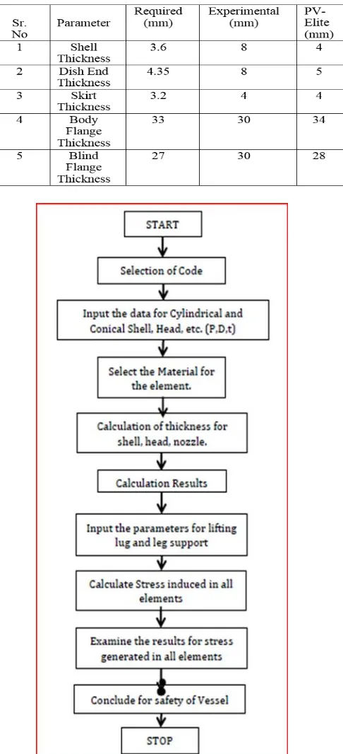
Design procedure followed ASME Code Section VIII. Analysis was carried out only on the following elements of pressure vessel: skirt, shell, dish end, body flange and blind flange. The step of analysis is illustrated on flow chart as shown on Figure 8. Material is selected according to purchase order. Design, Input parameter is given for every part. All the mathematical equation refers from ASME section VIII. For example for calculation, thickness is calculated using Equation 1
t = P.R/ (2SE- 0.2P) + CA ………..1
Where:
t= head thickness, mm
P = pressure, bar
R = radius of head, mm
S = stress of material, bar
E = joint efficiency
CA = corrosion allowance, mm
Maximum Allowable Working Pressure can be determined using Equation 2.
…………2
Where: ta = allowable thickness, mm.
Allowable thickness depends on the nominal thickness, corrosion allowance, head diameter and shell diameter.
The same equation would appear in the output screen whenever analysis menu was run. The similar step was conducted on different elements such as on shell, nozzle, dish end, skirt, flange and also nozzle.
Saddle is only available on horizontal type of pressure vessel and for vertical one the term is leg. Weight of each element and the total weight of pressure vessel had also calculated.
The output of analysis can be presented in many features. It can be in the form of table, or export to word processor in the form of final report. Since this research have not completed yet, the output would be presented as they are generated.
3. RESULT
Vertical pressure vessel is drawn per elements and the icon for each element can be found easily. The input parameter for each element also type in the suitable bar as can been seen on Figure 2 to figure 6. Once all the elements were connected, the pressure vessel would be as shown on Figure 5.
© 2018, IRJET | Impact Factor value: 6.171 | ISO 9001:2008 Certified Journal | Page 2666 Figure3. Dish End of vessel and the input data.
Figure4. Shell and the input screen.
Figure5. Body flange and the input screen
Figure6. Blind flange and the input screen.
Figure7. Geometry in PV-Elite
3.1 Results of Dish End analyzes
1. Required Thickness due to Internal Pressure [tr]:
= (P*D*Kcor)/(2*S*E-0.2*P)
=(15.400*398.0000*1.000)/(2*1167.10*0.70-0.2*15.400)
= 3.7583 + 0.0000 = 3.7583 mm
2. Max. Allowable Working Pressure at given Thickness,
Corroded [MAWP]:
© 2018, IRJET | Impact Factor value: 6.171 | ISO 9001:2008 Certified Journal | Page 2667 =(2*1167.10*0.70*4.0000)/(1.000*398.0000+0.2*4.0000)
=16.389 kgf/cm²
3. Maximum Allowable Pressure, New and Cold [MAPNC]:
= (2*S*E*t)/(K*D+0.2*t)
= (2*1167.10*0.70*4.0000)/(1.000*398.0000+0.2*4.0000)
= 16.389 kgf/cm²
4. Actual stress at given pressure and thickness, corroded [Sact]:
= (P*(Kcor*D+0.2*t))/(2*E*t)
= (15.400*(1.000*398.0000+0.2*4.0000))/(2*0.70*4.0000)
= 1096.700 kgf/cm².
5. Straight Flange Required Thickness:
=(P*R)/(S*E-0.6*P) + c
=(15.400*199.0000)/(1167.10*0.70-0.6*15.400)+0.000
=3.794 mm.
6. Straight Flange Maximum Allowable Working Pressure:
= (S*E*t)/(R+0.6*t) per UG-27
= (1167.10 * 0.70 * 5.0000 )/(199.0000 + 0.6 * 5.0000 )
= 20.222 kgf/cm².
7. Required Thickness due to Internal Pressure [tr]:
=(P*D*Kcor)/(2*S*E-0.2*P1-4(c)
=(0.169*398.0000*1.000)/(2*1167.10*1.00-0.2*0.169)
=0.0289 + 0.0000
= 0.0289 mm.
8. Max. Allowable Working Pressure at given Thickness, corroded [MAWP]:
=((2*S*E*t)/(Kcor*D+0.2*t))/1.67
=((2*1167.10*1.00*4.0000)/(1.000*398.0000+0.2*4.0000)) /1.67
= 14.019 kgf/cm²
9. Maximum Allowable External Pressure [MAEP]:
=min( MAEP, MAWP )
=min( 10.53 , 14.0193 )
=10.533 kgf/cm²
3.2 Results of shell analyzes
1. Required Thickness due to Internal Pressure [tr]:
=(P*R)/(S*E-0.6*P) per UG-27 (c)(1)
=(15.400*199.0000)/(1167.10*0.70-0.6*15.400)
=3.7941 + 0.0000 = 3.7941 mm
2. Max. Allowable Working Pressure at given Thickness, corroded [MAWP]:
=(S*E*t)/(R+0.6*t) per UG-27 (c)(1)
=(1167.10*0.70*4.0000)/(199.0000+0.6*4.0000)
=16.226 kgf/cm²
3. Maximum Allowable Pressure, New and Cold [MAPNC]:
=(S*E*t)/(R+0.6*t) per UG-27 (c)(1)
=(1167.10*0.70*4.0000)/(199.0000+0.6*4.0000)
=16.226 kgf/cm²
4. Actual stress at given pressure and thickness, corroded
[Sact]:
=(P*(R+0.6*t))/(E*t)
=(15.400*(199.0000+0.6*4.0000))/(0.70*4.0000)
=1107.700 kgf/cm²
3.3 Result of Reinforcement calculation,
Description: Nozzle N1
1. Reqd thk (a)of Cylindrical Shell, Tr [Int. Press]
=(P*R)/(S*E-0.6*P) per UG-27 (c)(1)
=(15.40*199.0000)/(1167*1.00-0.6*15.40)
=2.6468 mm
2. Reqd thk per UG-37(a)of Nozzle Wall, Trn [Int. Press]
=(P*R)/(S*E-0.6*P) per UG-27 (c)(1)
=(15.40*17.53)/(1202*1.00-0.6*15.40)
=0.2262 mm
3. Area Required [A]:
© 2018, IRJET | Impact Factor value: 6.171 | ISO 9001:2008 Certified Journal | Page 2668 =(41.3159*2.6468*0.5+2*3.5560*2.6468*0.5*(1-1.00))
=0.547 cm²
4. Area Available in Shell [A1]:
= d( E1*t - F*tr ) - 2 * tn( E1*t - F*tr ) * ( 1 - fr1 )
=41.316(1.00*4.0000-0.5*2.647) -2*3.556(1.00*4.0000-0.5 *2.6468)*(1 - 1.000)
= 1.106 cm²
5. Area Available in Nozzle Projecting Outward [A2]:
= (2* tlnp)*(tn -trn)*fr2/sin(alpha3 )
= (2*8.89)*(3.56-0.23 )*1.0000/sin( 64.5)
= 0.656 cm²
This document is template. We ask that authors follow some simple guidelines. In essence, we ask you to make your paper look exactly like this document. The easiest way to do this is simply to download the template, and replace (copy-paste) the content with your own material. Number the reference items consecutively in square brackets (e.g. [1]). However the authors name can be used along with the reference number in the running text. The order of reference in the running text should match with the list of references at the end of the paper.
4. DISCUSSION
Design of pressure vessel can be finished quickly by applying numerous calculations in software. The drawing process was simpler associated to other software.
[image:5.595.326.569.100.633.2]This research only investigated a part of parameter design. There are other parameters that are not considered such as thermal loads, wind loads, earthquake, transportation, erection, fabrication methods, etc. However this insufficiency can be overcome by mastering software.
Table -2 Comparative Analysis
Figure8. Process Flow chart
5. CONCLUSION
© 2018, IRJET | Impact Factor value: 6.171 | ISO 9001:2008 Certified Journal | Page 2669 Research can be explored to take into account other
parameters. The behaviors of pressure vessels in case of fluctuating load could be a challenging matter for future research.
6. REFERENCES
1. Arnold, K and Stewart, M., 1999, Surface Production Operation: Design of Oil-Handling Systems and Facilities,Gulf Professional Publishing Company, HoustonASME, 2007.
2. Boiler & Pressure Vessel Code: Rules for Construction of Pressure vessels, (ASME VIII), Division 1, ASME.
3. Cokorda and Mahandari, 2004, Design of pressure vessel by using MATLAB, Proceeding KOMMIT, Universitas Gunadarma,
4. Jakarta, Dionne, M.M., 1998,“The dynamic simulation of a three phase separator,” Master’s thesis, University of Calgary, Calgary.
5. Jimit Vyas and Mahavir Solanski, 2008, Design and Analysis of pressure Vessel, Dissertation,U.V. Patel College of Engineering, Gujarat Taylor,
6. T and Lucia,A 1995., “Modeling and analysis of multi component separation processes,” Separation Systems and Design, pp. 19–28, New York.
7. Mahandari and Sandi, “Mechanical design of pressure vessel for three phase separation by using software”.
8. A.A.Dagwar and A.B.Birari “Screw compressor manual” Department of research and engineering, Kirloskar Pneumatic Co Ltd Pune. (Feb-2018).