Real-Time Feature based Face Detection and Tracking
I-Cursor
Shashank Gupta
Dept. Of Computer Engineering Maharashtra Academy Of
Engineering, Alandi(D) Pune, India
Dhaval Dholakiya
Dept. Of Computer Engineering Maharashtra Academy Of
Engineering, Alandi(D) Pune, India
Sunita Barve
Master Of Engineering Maharashtra Academy Of
Engineering, Alandi(D) Pune, India
ABSTRACT
This project aims to present an application that is able of replacing the traditional mouse with the human face as a new way to interact with the computer. Facial features (nose tip and eyes) are detected and tracked in real-time to use their actions as mouse events. In our work we were trying to compensate people who have hands disabilities that prevent them from using the mouse by designing an application that uses facial features (nose tip and eyes) to interact with the computer. It can be applied to a wide range of face scales. Our basic strategy for detection is fast extraction of face candidates with a Six-Segmented Rectangular (SSR) filter and face verification by a support vector machine. A motion cue is used in a simple way to avoid picking up false candidates in the background. In face tracking, the patterns of between-the eyes are tracked with updating template matching.
1.
INTRODUCTION
In the past few years high technology has become more progressed, and less expensive. With the availability of high speed processors and inexpensive webcams, more and more people have become interested in real-time applications that involve image processing. One of the promising fields in artificial intelligence is Human Computer Interface which aims to use human features (e.g. face, hands) to interact with the computer. One way to achieve that is to capture the desired feature with a webcam and monitor its action in order to translate it to some events that communicate with the computer. In our work we were trying to compensate people who have hands disabilities that prevent them from using the mouse by designing an application that uses facial features (nose tip and eyes) to interact with the computer.
The nose tip was selected as the pointing device; the reason behind that decision is the location and shape of the nose; as it is located in the middle of the face it is more comfortable to use it as the feature that moves the mouse pointer and defines its coordinates, not to mention that it is located on the axis that the face rotates about, so it basically does not change its distinctive convex shape which makes it easier to track as the face moves. Eyes were used to simulate mouse clicks, so the user can fire their events as he blinks. While different devices were used in HCI (e.g. infrared cameras, sensors, microphones) we used an off-the-shelf webcam that affords a moderate resolution and frame rate as the capturing device in order to make the ability of using the program affordable for all individuals. We will try to present an algorithm that
distinguishes true eye blinks from involuntary ones, detects and tracks the desired facial features precisely, and fast enough to be applied in real-time.
We have aimed to design an application that uses facial features (nose tip and eyes) to interact with the computer. In this application, Facial features (nose tip and eyes) are detected and tracked in real-time to use their actions as mouse events. The coordinates and movement of the nose tip in the live video feed are translated to become the coordinates and movement of the mouse pointer on the user’s screen. The left/right eye blinks fire left/right mouse click events. The only external device that the user needs is a webcam that feeds the program with the video stream.
In our work we are trying to compensate people who have hand disabilities that prevent them from using the mouse.
2.
RELATED WORK
Most previous approaches to facial feature tracking utilize skin tone based segmentation from single camera exclusively (Yang & Waibel, 1996; Wu et al., 1999; Hsu et al., 2002; Terrillon & Akamatsu, 1999; Chai & Ngan, 1999). However, color information is very sensitive to lighting conditions, and it is very difficult to adapt the skin tone model to a dynamically changing environment in real-time Kawato and Tetsutani (2004) proposed a mono camera based eye tracking technique based on six-segmented filter (SSR) which operates on integral images (Viola & Jones, 2001)[1]. Each HCI method that we read about had some drawbacks, some methods used expensive equipments, some were not fast enough to achieve real-time execution, and others were not robust and precise enough to replace the mouse.
We tried to profit from the experience that other researchers gained in the HCI field and added our own ideas to produce an application that is fast, robust, and useable.
3.
FEATURE BASED FACE
DETECTION METHOD
were applied to images taken with certain restrictions (e.g. plain background, frontal view). These methods however have improved over time and become more robust to lighting conditions, face orientation, and scale. Despite the large number of face detection methods, they can be organized in two main categories: Feature-based methods, and image-based methods [2].
1. The first involves finding facial features (e.g. nose trills, eye brows, lips, eye pupils….) and in order to verify their authenticity performs geometrical analysis of their locations, areas, and distances from each other. This feature-based analysis will eventually lead to the localization of the face and the features that it contains. Some of the most famous methods that are applied in this category are skin models, and motion cues which are effective in image segmentation and face extraction. On one hand feature-based analysis is known for its pixel-accuracy features localization, and speed, on the other hand its lack of robustness against head rotation and scale has been a drawback of its application in computer vision.
2. The second is based on scanning the image of interest with a window that looks for faces at all scales and locations. This category of face detection implies pattern recognition, and achieves it with simple methods such as template matching or with more advanced techniques such as neural networks and support vector machines. Image-based detection methods are popular because of their robustness against head rotation and scale, despite the fact that the exhaustive window scanning requires heavy computations. More and more new detection methods are added to the arsenal of computer vision researchers, which proves once again the importance of this field and its ability of acquiring new ideas. Before over viewing the face detection algorithm that was applied in this work, here is an explanation of some of the idioms that are related to it.
4.
SSR FILTER FOR FACE CANDIDATE
[image:2.595.362.495.226.330.2]SSR Filter stands for: Six Segmented Rectangular filter. Each block represents a sector and the sum of the pixels of that sector is represented by Si.
Figure 1: Six-Segmented Rectangular (SSR) Filter. Average pixel values in each segment are computed and
compared with each other to find whether they satisfy certain conditions
To find face candidates the SSR filter will be used in the following way:
At first we calculate the integral image by making a one pass over the video frame using these equations [3]:
(1)
(2)
Where s(x, y) is the cumulative row sum, s(x,-1) = 0, and ii(-1, y) = 0.
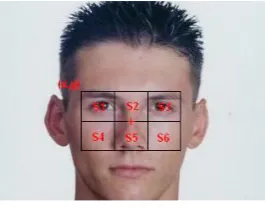
Figure 2 shows an ideal location of the SSR filter, where its centre is considered as a face candidate.
Figure 2: Ideal SSR filter location for a face candidate.
(x, y) is the location of the filter (upper left corner).
The plus sign is the centre of the filter which is the face candidate.
We can notice that in this ideal position the eyes fall in sectors S1 and S3, while the nose falls in sector S5. Since the eyes and eye brows are darker than the BTE and the cheek bones, we deduce that [4]:
(3)
(4)
[image:2.595.63.278.581.679.2]So in order to find face candidates we place the upper left corner (see Figure 01) of the SSR filter on each pixel of the image (only on pixels where the filter falls entirely inside the bounds of the image) . For each location (x, y) we check equations (3,4); if the conditions are fulfilled then the center of the filter will be considered as a face candidate. Eventually the candidates will group in clusters (see Figure 3).
Figure 3: Groups of face candidates. Each dot of each group is a face candidate discovered by the SSR filter and
the skin colour model.
S1 S2 S3
[image:2.595.364.495.618.717.2]The human face is governed by proportions that define the different sizes and distances between facial features (see Figure 4). We will be using these proportions in our heuristics to improve facial features detection and tracking.
Figure 4: A human face with different lines that define the facial features proportions.
5.
FACE CANDIDATE AND ROI
SELECTION
Checking all face candidates will be computationally heavy and unnecessary. What we are going to do is to find the clusters of face candidates and consider the centre of each cluster as the final candidate [4].
The clustering algorithm that was used is the following: Passing the image from the upper left corner to the lower right one; for each face candidate fc:
If all neighbours are not face candidates assign a new label to fc.
If one of the neighbours is a face candidate assign its label to fc.
If several neighbours are face candidates assign the label of one of them to fc and make a note that the labels are equal.
After making the first pass we will do another one to assign to each group of equal labels a unique label, so the final labels will become the clusters’ labels. We will be using a threshold that is relevant to the size of the currently used SSR filter, to eliminate clusters that are small. The centre of each cluster that is big enough is set with the following equations:
(5)
(6)
i is the pixel from the cluster, n is the cluster’s area.
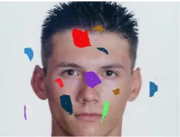
The final results are illustrated in figure 5 where the centres of the clusters that passed the threshold, are marked as white dots.
Figure 5: Clusters of face candidates and their centres.
5.1
Eye Tracking
[image:3.595.107.226.129.259.2]Eyes are tracked in a bit different way from tracking the nose tip and the BTE(Between The Eyes), because theses features have a steady state while the eyes are not (e.g. opening, closing, and blinking) [4]. To achieve better eyes tracking results we will be using the BTE (a steady feature that is well tracked) as our reference point [4]; at each frame after locating the BTE and the eyes, we calculate the relative positions of the eyes to the BTE; in the next frame after locating the BTE we assume that the eyes have kept their relative locations to it, so we place the eyes’ ROIs at the same relative positions to the new BTE (of the current frame) (see Figure 6). To find the eye’s new template in the ROI we combined two method s: the first used template matching, the second searched in the ROI for the darkest 5*5 region (because the eye pupil is black), then we used the mean between the two found coordinates as the eye’s new location. The problem with the darkest region method was that it picked the eyebrow sometimes as the eye (see fig. 7); here comes the eyebrow detection role where the eye’s ROI is placed under the detected eyebrow line to avoid picking it as the eye .
[image:3.595.334.509.478.560.2]Figure 6: Placing the eyes’ ROIs relatively to the BTE.
Figure 7: Darkest region method lead to false eye tracking.The right eyebrow was selected as the new eye.
Right Eye
[image:3.595.360.495.594.696.2] [image:3.595.126.246.640.698.2]Figure 8: Placing the eyes’ ROIs under the detected eyebrow lines has lead to correct eyes tracking.
5.2
Nose Bridge And Nose Tip Tracking
[image:4.595.103.230.284.380.2]Now that we located the eyes, the final step is to find the nose tip. So the first step is to extract the ROI; in case the face was rotated we need to rotate the ROI back to a horizontal alignment of the eyes.
Figure 9: The square that forms the ROI, and the ROI after extraction.
The nose tip has a convex shape so it collects more light than other features in the ROI because it is closer to the light source. Using the previous idea we tried to locate the nose tip with intensity profiles [5] .
We will be applying the following method.
At first we need to locate the nose bridge and then we will find the nose tip on that bridge.
As earlier mentioned the nose bridge is brighter than surrounding features, so we will use this criterion to locate the nose-bridge-point (NBP) on each line of the ROI. We will be using an SSR filter to locate the NBP candidates in each ROI line [5] (see Figure 10). The width of the filter is set to the half of the distance between the eyes, because from figure 5 we can notice that the yellow line (nose width) is equal to the half of the blue line (distance between the eyes).
Figure 10: SSR filter to locate nose bridge candidates.
After calculating the integral image of the ROI, each line of it will be scanned with this filter; we remember that the nose bridge is brighter than the regions to the left and right of it; in
other words the centre of the SSR filter is considered as an NBP candidate if the centre sector is brighter than the side sectors:
(7)
(8)
[image:4.595.402.454.334.389.2]In each line we might get several NBP candidates, so the final NBP will be the candidate that has the brightest S2 sector. In order to avoid picking some bright video noise as the NBP we will be using the horizontal intensity profile; so instead of applying the SSR filter to a line of the ROI we will be applying it to the horizontal profile calculated from the first line to the line that we are dealing with, because as already mentioned the values will accumulate faster at the nose bridge location, so by using the horizontal profile we are sure that we are picking the right NBP candidate not some bright point caused by noise; of course the results will get more accurate as we reach the last line of the ROI because the accumulation at the nose bridge location will get more obvious.
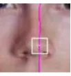
Figure 11: Nose bridge detection with the SSR filter and the horizontal profile.
Now that we located the nose bridge we need to find the nose tip on that bridge. Since each NBP represents the brightest S2 sector on the line it belongs to, and that S2 sector contains the accumulated vertical sum of the intensities in that sector from the first line to the line it belongs to, we will be using this information to locate the nose tip.
Figure 12: Nose tip detection result using nose bridge detection and first derivate calculation
6.
IMPLEMENTATION
6.1
Java Media Framework
The Java Media Framework (JMF) is a recent API for Java JMF is a framework for handling streaming media in Java programs. JMF is an optional package of Java 2 standard platform. JMF provides a unified architecture and messaging protocol for managing the acquisition, processing and delivery of time-based media. JMF enables Java programs to
I. Present ( playback) multimedia contents,
II. capture audio through microphone and video through Camera,
[image:4.595.402.454.511.567.2] [image:4.595.55.271.648.695.2]III. do real-time streaming of media over the Internet, IV. process media ( such as changing media format,
adding special effects), V. store media into a file.
6.2
Features of JMF
JMF supports many popular media formats such as JPEG, MPEG-1, MPEG-2, QuickTime, AVI, WAV, MP3, GSM, G723, H263, and MIDI. JMF supports popular media access protocols such as file, HTTP, HTTPS, FTP, RTP, and RTSP. JMF uses a well-defined event reporting mechanism that follows the “Observer” design pattern. JMF uses the “Factory” design pattern that simplifies the creation of JMF objects. The JMF support the reception and transmission of media streams using Real-time Transport Protocol (RTP) and JMF supports management of RTP sessions.
JMF scales across different media data types, protocols and delivery mechanisms. JMF provides a plug-in architecture that allows JMF to be customized and extended. Technology providers can extend JMF to support additional media formats. High performance custom implementation of media players, or codecs possibly using hardware accelerators can be defined and integrated with the JMF.
7.
FUTURE WORKS
Feature works may include improving the tracking robustness against lighting conditions; perhaps by using more sophisticated and expensive capturing devices such as infrared cameras that can operate in absence of light and give more accurate tracking results. Adding the double left click (detecting the double left eye blink) and the drag mode (enabling/disabling with the right double eye blink) functionalities. Adding voice commands to launch the
program, start the detection process, and to enable/disable controlling the mouse with the face.
8.
CONCLUSION
We are aimed to implement scale-adaptive face detection and tracking system using JAVA (J2ME) for face candidate detection, a six-segmented rectangle. (SSR) filter is scanned over the entire input image. This approach is similar to the window-scanning technique often used in the image-based approach. However, once the bright-dark relations between the six segments indicate a face candidate, eye candidate and nose tip regions are searched in the manner of the feature-based approach. Then, feature-based on the locations of a pair of eye candidates and nose tip, the scale, orientation and gray levels are normalized.The use of Java Millennium Edition helps it to be compatible even with pocket devices so, hopefully every new gadget or electrical appliance could be used by handicaps in future.
9.
REFERENCES
[1] P.Viola and M.Jones, “Rapid object Detection using a Boosted Cascade of Simple Features,” Proc. Of IEEE Conf.CVRP,1, pp.511-518,2001.
[2] Chiang, C. C., Tai, W. K., Yang, M. T., Huang, Y. T. & Huang, C. J., (2003). A novel method for detecting lips, eyes and faces in real-time. Real-Time Imaging 9, 277-287.
[3] Paul Viola, Michael J.Jones, “Robust Real-Time Face Detection”. International Journal of Computer Vision 57(2), 137–154, 2004.
[4] Shinjiro Kawato and Nobuji Tetsutani, “Scale Adaptive Face Detection and Tracking in Real Time with SSR filter and Support Vector Machine”.