An Image based Steganography Scheme Implying
Pseudo-Random Mapping of Text Segments to Logical
Region of Cover Image using a New Block Mapping
Function and Randomization Technique
Shiladitya Pujari
Assistant Professor University Institute of Technology Burdwan University, Burdwan, IndiaSripati Mukhopadhyay
ProfessorDepartment of Computer Science Burdwan University, Burdwan, India
ABSTRACT
This paper presented a new scheme of image based Steganography where the secret message is divided or segmented into random number of units holding equal number of characters and the cover image is logically divided into a random number of square blocks. Each logical block of image is used to hide each unit of message in a pseudo-random fashion. These mappings are done by using a new mapping function.
General Terms
Image based Steganography.
Keywords
Image-based steganography, pseudo-random sequence, secret message, block mapping, randomization.
1.
INTRODUCTION
Steganography is the art of hiding information into another covering media in a way that nobody except the receiver can detect the secret message and retrieve it. Steganography (which means “covered writing” in Greek) is an old art that has been used since the golden age of Greece where some practices were recorded like: writing a message on a wooden table then covering it with wax. Other techniques use invisible ink, microdots, converting channels and character arrangement.
Steganography is a type of cryptography in which the secret message is hidden in a digital picture. Steganography differs from Cryptography in the sense that where cryptography focuses on keeping the contents of a message secret, steganography focuses on keeping the existence of a message secret.
1.1
Steganography Methods
There are mainly three ways to hide a digital message in a digital cover [5][6].
Injection: Data injection embeds the secret message directly in the host medium. The problem with this kind of embedding is that it usually makes the host file larger, and therefore the alteration is easier to detect.
Substitution: Normal data is replaced or substituted with the secret data. This usually results in very little size change for the host file. However, depending on the type of host file and the amount of hidden data, the substitution method can degrade the quality of the original host file.
Generation of New Files: A cover is generated for the sole purpose of concealing a secret message. A sender creates a
picture of something innocent that can be passed to receiver; the innocent picture is the cover that provides the mechanism for conveying the message.
1.2
Image Based Steganography
Image based steganography methods use a cover image, preferably color image to hide the text message or another image inside it. The hidden text or image is a sort of secret message. The secret message is inserted inside the cover image by using any of the methods mentioned above. The most popular type of insertion method is known as Least Significant Bit (LSB) replacement method [1]-[3]. In this method, the least significant bit of each pixel of the cover image is replaced by bits of the secret message. The secret message is first converted entirely into bit stream. Then all those bits are substituted at the places of all least significant bits of all pixels. Each color pixel, or picture element of a digital picture is composed of three color components, Red, Green and Blue and each component is represented by eight bits or one byte. The value of each byte is the bit pattern stored in the bytes. When the least significant bit of the byte of any component is replaced by another bit value, change in the value is least. By replacing LSB of most of the pixels of an image makes no significant visual changes that can be detected by human eyes. In this fashion, an entire secret message can be inserted inside a cover image.
1.3
Review of Relevant Works
Various image based steganography method namely LSB (least-significant-bit), PVD (pixel-value differencing), GLM (gray level modification) and the method proposed by Ahmed et al. has been briefly mentioned in the following section.
1.3.1 Data Hiding by Least Significant Bit (LSB)
The most popular and common techniques is based on manipulating the least-significant-bit (LSB) [7], [8] and [9] planes by directly replacing the LSBs of the cover-image with the message bits. LSB methods typically achieve high capacity but unfortunately LSB insertion is vulnerable to slight image manipulation such as cropping and compression.
1.3.2
Data Hiding by Pixel Value Differencing
Method
1.3.3 Data Hiding by GLM
In 2004, Potdar et al. [10] proposes GLM (Gray level modification) technique which is used to map data by modifying the gray level of the image pixels. Gray level modification Steganography is a technique to map data (not embed or hide it) by modifying the gray level values of the image pixels.
1.3.4 Data hiding by the method proposed by
AHMAD et al.
In this work a novel Steganography method for hiding information within the spatial domain of the gray scale image has been proposed. The proposed approach works by dividing the cover into blocks of equal sizes and then embeds the message in the edge of the block depending on the number of ones in left four bits of the pixel.
2.
THE PROPOSED SCHEME
In this research paper, we used the LSB method as the fundamental replacement method for insertion of each bit of the secret message inside a cover image. The paper presented a new image based steganography scheme in which both the secret message as well as the cover image is divided into a number of small but equal sized portions [1]. After that division method, separate portions of the text are embedded into different portions of the cover image by using LSB method at the bit level, but a portion of the cover image for a portion of text is selected in a pseudo-random fashion. This method makes the embedding or insertion process difficult, but imposes more security [4]. Analysis may help to detect that steganography has been implied on the cover image, but attackers cannot be able to extract the secret message from the cover image without knowing the parameters used in this process.
This new steganography method is block mapping method. The entire Steganography process has two parts. One part is to insert or hide the secret text message inside a cover image, preferable colored image. This process is done at the sending end. Another part is used at the receiving end to extract the original secret text message from the stego-image.
3.
DESCRIPTION OF EMBEDMENT OF
SECRET IMAGE
At the sending end, the text message is inserted in a cover image and the host cover image or the stego-image is sent to the intended receiver. The insertion process is a complex process and involves some mathematics at various steps. A digest function is included to calculate an integer number that is one of the necessary parameter of the mapping function used here. Another randomization function called Gear-box randomization function is also used to randomize the bit stream of each portion of text, or called units to impose more security. This randomization function is reversible function, i.e. the function generates a random sequence of a bit stream input, but it can also regenerate the original sequence when the randomized sequence is taken as input. In this paper, we have only described the new steganography method without describing the password digest function and gear-box randomization function in details. We analyzed some results only by taking values from those functions. The insertion method involves various steps where different kind of
operations is done. The different steps are described in the following section of this paper.
3.1
The Message Insertion Method
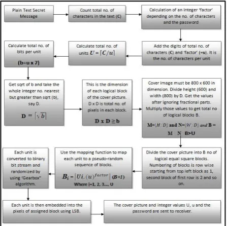
[image:2.595.317.541.191.414.2]The following diagram represented the insertion of hiding technique of secret text message in a colored picture. A total of seventeen steps are involved in this technique. The algorithm also included a new randomization technique, called gear-box randomization technique.
Fig 1: Pujari’s algorithm for image steganography
The steps of the algorithm are explained here.
Step I: At the first step, the secret text message is taken as input and total number of characters in the text message is counted. This total number of characters is designated as C.
Step II: A unique integer number named factor is calculated. Factor is calculated through a digest mechanism. The digest algorithm takes a one-time password and the text message as input and depending on the total number of characters and strength of password, factor is calculated.
Step III: This Steganography algorithm segments or divides the entire text into some equal sized packets called Units. Every unit of text holds equal number of characters. For doing this segmentation into units, numbers of characters are counted from the beginning of the text. The size of units varies and depends on the number of characters in the text and the value of factor. The size is calculated by adding the digits of C, which is the total number of characters in the text and factor. This is called u, i.e.
u = sum of digits of C +
factor
.
… (1)
Step IV: This step calculates the total number of units required. Counting of characters is started from the beginning of the text, and the entire text is segmented into the units. As u or the size of unit is always not a factor of the total number of characters, the last unit may hold number of characters which is less than that of the size of unit. In hat cases, the last unit is stuffed with spaces to make the character number equal. If C is divided by u, then the result may not be always a whole number. C/u normally gives the total number of units. But in case of fractional result, number of units must be calculated by taking the right ceiling value of the result of C/u. In those cases, space stuffing is required for the last unit, means extra spaces will be appended after the last character of the text message to make the character number equal. Total number of units is calculated using a ceiling function:
U =
𝐂/𝐮
… (2)
Where U is number of units, C is number of characters, u is the unit size.
Step V: Now total number of bits in a unit of text is calculated by multiplying u with 7 (each character is of 7 bits). Each bit requires a pixel of cover image for hiding purpose. That’s why number of bits per unit is required. (b = u × 7) gives the minimum number of pixel required to hide a unit of text.
Step VI: This algorithm is based on hiding of text into equal sized square blocks of cover image. That means, the cover image must be divided into a number of logical square blocks of equal size or equal dimension. Each logical block will hide a particular unit of text and this process is done in a pseudo-random fashion. As because the dimension of each logical block of image is square, we have to find out the square root of b and get the whole number nearest and larger than sqrt of b. This number gives the dimension of each logical block of image that hides a unit of text, i.e. right ceiling of root of b:
D =
𝐛
… (3)
Step VII: The dimension is then calculated as D × D. This is the size of each square shaped logical block of the cover image. To make the hiding process successful, D × D must be less than or equal to the number of bits in a unit (b), i.e.
D × D ≥ b or D2 ≥ b.
Step VIII: The general restriction is set on the dimension of cover image such as cover image must be an 800 × 600 picture. That means width of the cover picture W is 800 pixels and height H is 600 pixels. D is the dimension of each logical square block. After dividing height and width of the cover image by D, and ignoring the fractional part of the results, we will get M = H/D and N = W/D. M and N are the number of logical divisions along with height and width of the picture and length of each division is D. If we multiply M and N, then the result gives the total number of logical blocks of image.
B = M × N, where B is total number of blocks. B must be greater than U, i.e. B > U.
M= 𝑯/𝑫 and N= 𝑾/𝑫 and B = M × N
… (4)
Step IX: In this step, the entire cover image is segmented into B number of logical square blocks. A bitmap image is a matrix or two-dimensional array of pixel values. The first pixel of the image is denoted as [0, 0], the second pixel of first row is denoted as [0, 1], the second pixel of first column is [1, 0] and so on.
As the dimension of each block is D, the four corner pixels of first block (block no. 1) are [0, 0], [0, D-1], [D-1, 0] and [D-1, D-1]. Similarly the second block (block no. 2) is demarked by four pixels [0, D], [0, 2D-1], [D-1, D] and [D-1, 2D-1]. The limits are M and N values row and column wise respectively.
Step X: After segmentation of the cover picture into B number of logical blocks, each block will be assigned for a specific unit of text to hide into. This assignment of block number to the units is done in a pseudo-random fashion using a mapping function. Mapping is done in pseudo-random fashion so that during extraction, the same pseudo-random sequence can be generated, but it will be difficult to predict any pattern of mapping. The mapping function involves Ui or unit number, u or unit size, factor and B or total number of blocks.
B
i= F
mapping(U
i, u, factor, B)
To generate a pseudo-random sequence that will specify the particular regions for each unit of text, location identification numbers or region identification number, also called as block numbers must be unique, whatever the number of blocks should be. Another restriction must be maintained here which is the upper bound of the generated number. The values must not exceed the total number of blocks (B). This implies that the function must be a modulus function of B or (B+1). To generate the pseudo-random sequence having sufficient spaces between the numbers so that probability of getting overlapped or to avoid collisions between those numbers, a minimum spacing is introduced by including the integer value
u
and a power of factor value. Experimental result shows that the mapping function works best if the expression will be as follows:B
i=
𝑼𝒊. (𝒖)
𝒇𝒂𝒄𝒕𝒐𝒓(
B+1
) … (5)
Where i=1, 2, 3 … U. Bi is a pseudo-random number generated for a specific value of Ui. Bi is the block number of unit number Ui.
the process one time and strength of randomization depends on the strength of password.
Step XII: As per the mapping sequence, each unit (now a packet of randomized bit stream) is hidden or inserted into the specified block and each bit is inserted into individual pixels using Least Significant Bit replacement (LSB) technique.
[image:4.595.317.545.145.283.2]Step XIII:After insertion of all units, the stego image is sent to the receiver along with the values of u, U and factor. The user defined password must be known to receiver to retrieve the original secret text embedded into the stego image.
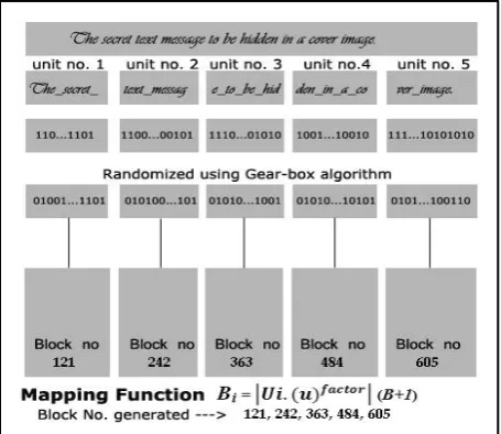
Fig 2: Text segmentation and mapping to blocks of image
Fig 3: Units are converted to bit stream, then randomized and embedded into specific blocks
A pictorial representation can be more helpful to understand the mapping process better. Fig 2 describes the calculations behind the finding of block numbers assigned to specific unit of texts in a pseudo-random fashion. In this example, the secret text message contains 54 (C) characters including
[image:4.595.55.283.228.420.2]spaces and punctuations. And factor value is set to 2. After calculations, the pseudo-random sequence of block numbers has been generated and mapping can be done accordingly. A perspective view of this mapping may be more helpful for better understanding.
Fig 4: A more realistic view of the mapping process
3.1.1
Finding the Exact Position of each Logical
Block of the Cover Image
The cover image is divided logically into M rows and N columns where M= 600/𝐷 and N= 800/𝐷 . That means row numbers are 1, 2, 3… M and column numbers are 1, 2, 3… N. If we divide the block number with N (no. of columns), then (Quotient+1) gives the row number on which the block is positioned and Remainder (R) gives the exact position or column number of the block on that row. If the block number is less than N, then only Remainder gives the exact position of the block on row 1.
If Bn is the block number, and Bn >N, then after dividing Bn with N, (Q+1) is the row number, R is the column number.
Fig 5: Procedure to find the exact position of a block
3.1.2
Finding the Exact Pixel Position of each
Logical Block within the Cover Image
[image:4.595.55.283.460.657.2] [image:4.595.316.543.528.682.2]second pixel on first row is denoted as [0, 1] and so on. Similarly, second pixel on first column or first pixel of second row is denoted as [1, 0] etc. In this Steganography scheme, each logical block is a square of dimension D × D. each square has four corner points which are actual pixels in the cover image.
Fig 6: Division of the cover picture into blocks and position of corner pixels of blocks
[image:5.595.53.285.154.340.2]Our goal is to determine the exact position of the top-left pixel of a block and find out the positions of other pixels within that block. This is necessary because each unit of text will be embedded in a block, i.e. into the pixels of that logical block, which are the actual pixels of the cover image. In this context, rows and columns of those blocks are denoted as I=1, 2, 3 … M and J=1, 2, 3…N. Now corner pixel positions of a specific block is determined as
Fig 7: Determination of corner pixels of a block
For example, suppose Bi or block number is 125 and N is 20. Then dividing 125 by 20 gives (Q+1) = (6+1) = 7 and remainder R = 5. The block is positioned at 7th row and 5th
column. Then I=7 and J=5. Four corner pixels in the cover image are denoted as
Fig 8: Corner pixel position of a logical block of image
If the value of D is 9 as in Fig 7, then all four corner pixels are [54, 36, [54, 44], [62, 36] and [62, 44] accordingly.
More specifically, for the first block (block no. 1), the row and column no. is 1. The corner pixels are [0, 0], [0, D-1], [D-1, 0] and [D-[D-1, D-1] as determined and shown in the following figure
After determining the top-left and bottom-right corner pixel positions of a block, bits can be embedded using LSB algorithm into the pixels.
4.
MESSAGE EXTRACTION METHOD
[image:5.595.318.542.400.507.2]The extraction of original secret message is done at the receiving end.
[image:5.595.53.284.493.676.2]The original text message can be retrieved through the processes which are depicted in Fig 9 above. The stego-image is sent along with the secret password (one –time) and two essential parameters U and u. the steps involved in this extracting method are describe bellow.
Step I:At the receiving end, the stego-image along with the secret one-time password and two parameters U and u are available. Without these values, extraction of the original message cannot be done. To calculate the factor value, total number of characters in the message is required, which can be derived by multiplying U and u. Then with the help of C (=U
× u) and password, factor can be regenerated using the same digest function.
Step II: Then total number of bits in a unit is calculated by multiplying u with 7.
Step III: The same process is done as in equation (3) described earlier in section 4 of this paper to calculate the value of D, the dimension of each logical block of stego-image. The checking condition is similar as stated before, i.e.
D × D ≥ b or D2 ≥ b.
Step IV:The stego-image is the segmented into B number of logical blocks by applying the equation (4) described in section 4. That gives the total number of logical block of image B = M × N. Obviously B > U.
Step V: The stego-image is then divided into B number of logical blocks and numbered similarly as in insertion process.
Step VI: The block mapping function is then applied to get the same pseudo-random sequence for every unit Ui. This sequence gives the block numbers for every unit of text.
Step VII: Locating the exact position of each block of image and then identifying four corner pixels of each block is same as described before. After doing these processes, each randomized bit stream embedded in those blocks are retrieved as per the pseudo-random sequence. The number of bits embedded using LSB method into each block is counted by multiplying u with 7 (u x 7). Extra pixels are not considered for extraction.
Step VIII: All the extracted bit streams of each unit are de-randomized using the Gear-box randomization function, and original sequences of bits are generated. These sequences are the binary form of every text units including spaces and special characters.
Step IX: After step VI, all units are merged and converted to original character set to get the original secret text message.
This is the entire extraction method explained above. In this paper, we didn’t describe some important aspects that are involved in the entire insertion and extraction process. The algorithm imposes some randomization of bit stream of each unit. That randomization is done with the help of a
randomization function named as gear-box randomization function. The function is named so because the working procedure of the function is relevant to the mechanical gear-box of an automobile. The function posses a variable number of cog-wheels like the automobile gear-wheels to generate the random sequence of bits. Number of cog-wheels as well as number of cogs per wheel depends on a variable input of the function. The ratios of diameters of wheels are also varying depending on some input value. The randomization function is a reversible function, which means if all the input variables remain same, then the function regenerates the original sequence from the randomized sequence generated previously.
Another function is not described in this paper. This function is one kind of message digest function and used here to calculate the value of the variable factor. This value is calculated on the basis of strength of the user password and the total number of characters in the secret text message. Generally factor value lies within the range 2 to 9 because practical experiment shows that above this value, the time taken by the block mapping function is too much and output values goes beyond the range.
5.
EXPERIMENTAL RESULTS
[image:6.595.315.543.530.729.2]Experimental result shows the calculations and equations involved in this steganography scheme works well. Here, Total number of characters in the text message is assumed as C = 23 and factor = 2. Then number of units U = 4, characters per unit u = 7, bits per unit b = 49, block dimension D = 7. The cover image is a 800 x 600 pixels image, i.e. height H = 600 and width W = 800. Then M = 85, N = 114. The block mapping function generates the pseudo-random sequence for four units of texts as 49, 98, 147 and 196. The table below showing values of I and J for each block and corner pixel position of blocks in the actual cover image.
Table 1: corner pixel positions of each block cover image
Unit No.
Block No.
Row No.
(I)
Col. No. (J)
Corner pixels
1 49 1 49
[0, 336] [0, 342]
[6, 336] [6, 342]
2 98 1 98
[0, 679] [0, 685]
[6, 679] [6, 685]
3 147 2 33
[7, 224] [7, 230]
[13, 224] [13, 230]
4 196 2 82
[7, 567] [7, 573]
6.
CONCLUSION
This steganography algorithm implies a better level of security because before embedding the characters of the secret text message into a cover image using LSB, the entire text is chopped up and each segment are randomized at bit level. Again all the segments of text are randomly inserted into different regions of the cover image. A space-stuffing method is used to make the number of characters of each unit equal. A new pseudo-random sequence generator function is used to generate a pseudo-random sequence to embed each of the unit of secret message into the logical square regions or blocks of the cover image in a random fashion. Using the same pseudo-random sequence, extraction can be done to get the original message. As mentioned earlier, the input value named factor of the pseudo-random sequence generator function is depends on the secret password known to the two intended parties (sender and receiver) only. As this is a secret key, another level of security is also imposed here. This method can be improved again by increasing the strength of factor value generation function, modifying the method of calculating the total number of characters in each unit of message and also by imposing the randomization function (Gear-box randomization function) at the character level as well as at the bit level.
7.
REFERENCES
[1] Huang W, Zhao Y and Rong-Rong Ni, Block-based Adaptive Image Steganography using LSB Matching Revisited, Journal of Electronic Science and Technology, Vol. 9 (4), 2011
[2] Luo W, Huang F and Huang J, Edge Adaptive Image Steganography Based on LSB Matching Revisited, IEEE
Transaction on Information Forensics and Security, Vol. 5 (4), June 2010.
[3] Yang C and Wang S, Transforming LSB Substitution for Image-based Steganography in Matching Algorithms, Journal of Information Science and Engineering 26, 1199-1212, 2010.
[4] Shiva Kumar K B, Raja K B, Chhotaray R K, Pattanaik S, Bit Length Replacement Steganography Based On DCT Coefficients, International Journal of Engineering Science and Technology, Vol. 2 (8), 3561-3570, 2010.
[5] T Mrkel, JHP Eloff and MS Olivier.”An Overview of Image Steganography,” in proceedings of the fifth annual Information Security South Africa Conference, 2005.
[6] L.Y. Por and B. Delina, “Information Hiding: A New Approach in Text Steganography”, 7th WSEAS International Conference on Applied Computer & Applied Computational Science, April 2008, pp- 689-695.
[7] Analysis of LSB Based Image Steganography Techniques ,R. Chandramouli, Nasir Memon, Proc. IEEE ICIP, 2001.
[8] J.Y. Hsiao. C.C. Chang. and C.-S. Chan. Finding optimal least significant- bit substitution in image hiding by dynamic programming strategy. Pattern Recognition, 36:1583–1595, 2003.
[9] Potdar V.and Chang E. Gray level modification steganography for secret communication. In IEEE International Conference on Industria lInformatics, pages 355–368, Berlin, Germany, 2004.