Feng Tian
*, Hanqing Li and Liangchen Yuan
Abstract
Existing software radio platforms constructed by discrete devices have many disadvantages, such as high power consumption, high cost, and poor portability. In this study, an AD9361-based software radio communication system was designed on the basis of the zero-IF bandpass sampling software radio structure to solve the poor universality and expansibility problem of traditional software radio receivers. In the AD9361-based software radio communication system, the influences of channels on received signals and the inter-symbol interference caused by the multipath configuration are offset and eliminated by the minimum mean-squared error (MMSE) equalization algorithm. The simulation analyses on the core functions, including group detection, frame synchronization, channel estimation, and frequency-domain equilibrium, of the designed receiver was performed by ModelSim. The receiving functions of the software radio were realized by the core radio frequency (RF) board of AD9361 and the digital baseband development board of ZC706. The signal frequency spectra received and sent by the designed receiver overlap on the basis of the joint debugging and testing of the RF and digital baseband modules. Test results demonstrate that the designed software radio receiver has a reasonable structural design and can meet the design requirements in terms of overall performance. Additionally, the repeated development process of traditional software radio receivers is simplified, and the integration level and
expansibility of the system can be improved. The results can provide valuable references for the development of universal software radio receivers.
Keywords:Software radio, Receiver, AD9361, Frequency-domain equalization, Channel estimation
1 Introduction
Software radio has overcome the disadvantage that previous communication platforms with different communication functions and frequency bands cannot communicate mutu-ally. Existing software radio platforms are constructed by discrete devices, which are constrained by high power con-sumption and high cost. This situation not only requires technicians to be experienced in hardware design and radio frequency (RF) signal processing, but it also poses high ac-cess requirements for software. Given the coexistence of 3G and 4G communication standards, and even that of 5G, there are multiple frequency bands around the world. Trad-itional software radio designs require different hardware platforms to support varied communication protocols and frequency bands, and they require long development periods and high design costs.
Andrews et al. [1] suggested the use of a mixer as the first-level structure of a software radio to reduce noise at the cost of power with the supply voltage of the baseband low-noise amplifier increased. Murphy et al. (2012) put forward the use of a noise-canceling technology as the software radio structure. Useful sig-nals were enhanced by increasing the auxiliary chan-nels and offset noises at the output terminal, thus improving the noise reduction capability and the overall performance of the software radio system [2]. Zhang et al. propounded a software radio technique that can eliminate the spatial incident angle interfer-ence and frequency interferinterfer-ence in signal filtering [3].
Loubser and Swart [4] encoded two existing
CR-specific media access control protocols by using a CR-specific simulator. Kamaleldin and Ahmed put forward that hardware platforms of software radio system which support many wireless standards could be realized by dynamical program reconfiguration [5].
Marwanto et al. [6] proposed ARDUINO UNO and
© The Author(s). 2019Open AccessThis article is distributed under the terms of the Creative Commons Attribution 4.0 International License (http://creativecommons.org/licenses/by/4.0/), which permits unrestricted use, distribution, and reproduction in any medium, provided you give appropriate credit to the original author(s) and the source, provide a link to the Creative Commons license, and indicate if changes were made.
* Correspondence:[email protected]
X-Bee technologies for software radio systems to reduce the costs of spectrum exchange information based on OFDM. Sahoo et al. propounded a multi-channel finite impulse response filter for software radio, which can reduce power consumption effect-ively by the launcher umbilical tower, and can be ap-plied to software radio systems with multichannel filter efficiently [7].
Tsinghua University (2014) completed a chip for software radio receivers in the working frequency band of 0.1–5 GHz. Qin and Wang et al. constructed a radio communication system platform in Matlab and a univer-sal software radio peripheral to increase the utilization of spectrum resources. Spectrum sensing and available spectral bandwidth estimation of signals of master users were obtained by performing an energy detection method. Thus, spectrum detection was realized, and a set of judgment criteria was provided for the spectral access of secondary users [8]. Xu and Yu designed and completed a fault prediction software platform for an airborne software radio system by analyzing its structure [9]. Cui [10] designed a communication terminal for the time-hopping spread spectrum of the TDMA system based on the software radio concept, realized the single-channel launching and multichannel reception of RFs, and accomplished the design of RF modules and their link terminals. Zhang et al. [11] designed a moni-toring system over interferences and multipath in the signal bands and adjacent frequencies of current four navigation systems based on software-defined radio con-cept. Yin and Cheng [12] built a new hardware design program for the software radio processing platform with high-performance and low power consumption based on the requirements of special radio communication sys-tems with low power consumption.
Extant studies have reported that software radio systems are generally limited by their structures. Studies based on AD9361 RF modules and processing modules of SOC digital basebands remain underex-plored. Covering most bands with the charter and license-free bands, the working frequency range of AD9361 is from 70 MHz to 6.0 GHz. The supported channel bandwidth is from less than 200 kHz to 56 MHz. With the RF front end and the baseband of the flexible mixed signal integrated, AD9361 provides a configurable digital interface for the processor and in-tegrates frequency synthesizer, thus simplifying the import of the design, which can achieve lower noise and higher accuracy of modulation with the high programmability. In this study, an AD9361-based soft-ware radio structure was constructed by using the broadband zero-IF bandpass sampling software radio structure. The corresponding software radio receiver was designed, which achieved many core functions,
such as group detection, frame synchronization, chan-nel estimation, and frequency-domain equilibrium. The results can provide new universal platforms and methods for software radio receivers.
2 Methods
2.1 Structure of software radio system
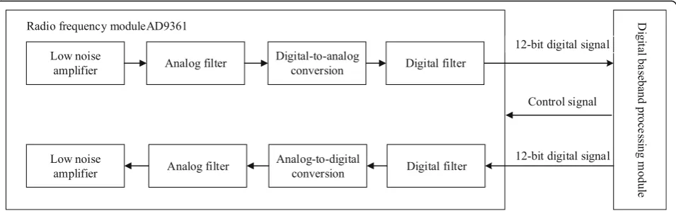
The software radio system is mainly composed of RF module and digital baseband processing module. The RF module converts RF analog signals to baseband digital signals and vice versa, and it facilitates RF re-ceiving and transmitting. The communication proto-col in the physical layer is realized by the digital baseband processing module, which ensured signal encoding/decoding, and facilitated modulation and de-modulation [13]. The structure of the software radio system is shown in Fig. 1.
2.2 Implementation of software radio receiving terminal The receiving terminal of the software radio performs group detection, frame synchronization, channel esti-mation, frequency-domain equilibrium, RS decoding, inverse mapping, and so on. In the main signal pro-cessing of the digital baseband receiving module, the first step is to conduct group detection, followed by signal synchronization and channel estimation based on training sequences. Then, signals are balanced on the basis of data from channel estimation to compen-sate for the frequency-selective fading of signals caused by multipath transmission. Finally, RS decod-ing and 16QAM demodulation are accomplished. The structure of the software radio receiver is shown in Fig. 2.
2.3 The structure of AD9361
AD9361 is composed of the 2 × 2 transceiver, the con-figuration interface of Serial Peripheral Interface (SPI), the AUXADC, internal PLLs, the programmable GPO, and the data bus of 2 × 12 bits which can be config-ured as differential or single terminal. Each transmit-ting and receiving channel of AD9361 is independent. The two receiving channels are composed of low-noise amplifier, mixer, amplifier, filter, and ADC. The two transmitting channels are composed of DAC, fil-ter, amplifier, low-noise amplifier, and mixer. The configuration interface of SPI is compatible with the
standard mode of four lines. The structure of
AD9361 is shown in Fig. 3.
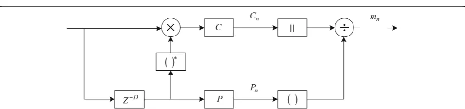
2.4 Group detection
The value of delay correlationCnis:
Cn¼
XL−1
k¼0
rn−krn−k−D; ð1Þ
where rn is the received signal, and Cn is the mutual correlation between the currently received L data and theLdata received beforeD.
The value of received signal energyPnis:
Pn¼
XL−1
k¼0
rn−k−Drn−k−D¼
XL−1
k¼0
rn−k−D
j j2: ð
2Þ The decision variable mn of the delay correlation
algorithm is:
mn¼
Cn
Pn
¼ jXL−
1
k¼0
rn−krn−k−Dj
XL−1
k¼0
rn−krn−k−D
: ð3Þ
The value ofmnfor group detection can be determined
by the leading structure when the signal-to-noise ratio (SNR) is 15 dB. A value ofCnapproaching 0 indicates that
effective data transmission has not been achieved and only noise exists. Parameter mn begins to increase with the
occurrence of the secondary short-training symbol and begins to decrease when the ninth period is reached.
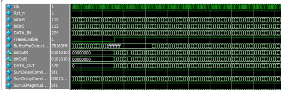
A simulation on the basis of the ModelSim platform is conducted. The simulation results of group detection are shown in Figs.5and6.
DataInRe and DataInIm are the real part and imagin-ary part of the current data, respectively. SumMagnitude is the sum of relevant window energies, and SumDelay-Correlation is the sum of correlation coefficients of rele-vant windows. BufferForDetection represents the initial judgment samples of 32 continuous groups, and Buffer-ForDetection represents the judgment samples at the end of 48 continuous groups. As shown in Figs.4and5, SumMagnitude and SumDelayCorrelation are immedi-ately calculated after a system reset and when the effect-ive signal of the grouping detection elevates. When 32 samples are detected continuously, data grouping of judgment arrives. When the SumMagnitude of the 48 continuous samples is smaller than the threshold, the data grouping is completed.
2.5 Frame synchronization
The frame synchronization of signals requires the calcula-tion of the cross-correlacalcula-tion coefficient between the received data groups and the locally known short-training
Fig. 1The structure of the software radio system. The software radio system is mainly composed of an RF module and a digital baseband processing module
Fig. 3The structure of AD9361. The whole circuit of RF and IF signals is integrated into one chip by adopting zero-IF architecture, which is composed of the transceiver, the configuration interface of SPI, the AUXADC, the internal PLLs, the programmable GPO, and the data bus
Fig. 4Circuit procedure for group detection. Group detection is performed by using the leading structure.Cnis the mutual correlation between the
currently receivedLdata and theLdata received beforeD.Pnis the value of received signal energy.mnis the decision variable of the delay
symbols [15]. Cross-correlation coefficient Ck can be
expressed as:
Ck¼
XD−1
m¼0
rk−mSm; ð4Þ
where the superscript∗is a conjugation, andDis the length of the cross-correlation coefficient, which is determined to be 16. The positions of the short-training symbols are judged according to the value of∣Ck∣. The moment of the last peak of ∣Ck∣ is designated as the end point of the short-training symbols.
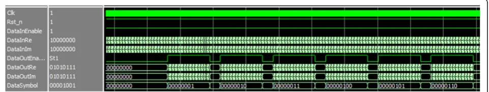
The simulation results of frame synchronization based on the ModelSim platform are shown in Fig. 7.
DataInRe and DataInIm are the real part and imaginary part of input data, respectively. DataInEnable is the enable signal of input data, and PCouter is the number of de-tected peaks. First, quantization is implemented when the data to be synchronized arrives. Then, the correlation is calculated on the basis of the 16 local short-training
symbols, and the moment at the ninth peak is viewed as the end point of the short-training symbols. Finally, long-training symbols and data symbols are designated with serial output according to the output format with the cyc-lic prefix eliminated at the same time. As shown in Fig.7, DataOutEn is the effective time for outputting one symbol denoted as 1 and 2 successively which calculates from the long-sequence, with the data symbols started from 3. This scheme is viewed as one cycle of output data.
2.6 Channel estimation
Channel estimation is first performed to estimate the received signals from the time domain, according to which the estima-tion of frequency domain can be easily obtained [16]. Then, the received signals of the estimator can be expressed as:
r tð Þ ¼s tð Þ h tð Þ þn tð Þ; ð5Þ where h(t) is the impulse response, r(t) represents the received signals, s(t) denotes the theoretically received Fig. 5The simulation diagram 1 of group detection. The value ofmnfor group detection can be determined by the leading structure when the
signal-to-noise ratio (SNR) is 15 dB
signals, and n(t) is the signal noise. The estimated value of the input signal ^sðtÞ is produced by the con-volution of inverse channel system ^hðtÞ that is com-posed of r(t) andh(t), where hðtÞ ^hðtÞ ¼δðtÞ.
^s tð Þ ¼½s tð Þ h tð Þ þn tð Þ h t^ð Þ
¼s tð Þ h tð Þ ^h tð Þ þn tð Þ ^h tð Þ
¼s tð Þ þ^n tð Þ
ð6Þ
The estimation of the channel frequency response of the frequency domain can be deduced directly from the time domain. Channel frequency responseH(jω) is estimated by usingr(t), and the inverse channel system H^ðjωÞ is con-structed by usingH(jω). Therefore,
^s tð Þ ¼F−1½F S tf ð Þg H jwð Þ H jw^ð Þ
¼ F−1F s tfð ÞgH jwð ÞH jw^ð Þ þN jwð Þ H jw^ð Þ
¼s tð Þ þ F−1N jwð Þ H jw^ð Þ;
ð7Þ whereH^ðjωÞ ¼Hð1jωÞ.
Channel estimation is realized by the unique words (UW) inserted into the data sequence. If UW is {xm} with a length
ofP, then the channel frequency response H^k can be
esti-mated by FFT from the transmitting sequences {xm} and
{ym} to {xm} and {Ym}. The corresponding time-domain discrete signal {hm} can
be initially obtained from the IFFT operation of H^k at the
point P, where P denotes the length. Then, the
zero-padding operation of {hm} is performed, thus
obtain-ing the {hm} of the pointM. Finally, the frequency response
valueH^kis acquired from the FFT operation of {hm} of the
pointM.
The frequency domain is calculated on the basis of the time domain as part of the channel estimation. The re-ceived signals can be expressed by the Y=XH+Vmatrix as follows:
JLS¼ðY−XHÞHðY−XHÞ; ð9Þ
where X= diag[X(0),X(1), …,X(Np−1)],Y= [Y(0),Y(1), …,Y(Np−1)]T, and H= [H(0),H(1), …,H(Np−1)]T. Np is the number of UW. The first-order derivative and the second-order derivative of JLS for H are calculated as follows:
Thus, the estimated value denoted by H^LS can be
expressed as:
^
HLS¼X−1ðXHþVÞ ¼HþX−1V ¼Hþn; ð13Þ
wherenis the estimation error, andn=X−1V. The simu-lation results of channel estimation based on the Model-Sim platform are shown in Fig.8.
DataInRe and DataInIm are the real part and imagin-ary part of input data, respectively. DataInEnable is the enable signal of input data, and ChannelcoeEnable is the enable signal of output data. ChannelcoeIm and Chan-nelcoeRe are the real part and imaginary part of output channel estimation, respectively.
2.7 Frequency-domain equilibrium module
Frequency-domain equilibrium is performed to offset the effects of channels on the received signals. Here, the minimum mean-squared error (MMSE) equilibrium
algorithm is applied as the frequency-domain equilib-rium [17].
Suppose that the set of transmitting data is denoted by s (s= [s0,s1, …,sN−1]T), N is the number of FFT
points (h= [h0, …,hL−1.0, …, 0]T), and L is the length
of impulse response. Then, the received signal vector is r= [r0,r1, …,rN−1]T. Accordingly,
Vk are the frequency domain values of received sig-nals, transmitting signals and channel impulse re-sponse function, and additive white Gaussian noise.
If the equilibrium coefficient isWk, then the
frequency-domain output after equilibrium is:
~
Sk¼WkHkSkþWkVk: ð16Þ According to its definition, the mean square error (MSE) after the equilibrium can be deduced.
MSE¼EX
Suppose that σ2N is the noise power on the frequency domain andσ2
S is the signal power on the frequency
do-main, then:
whereFkuses the lower limit value based on the condi-tion of argWkHk= arg 1 = 0.
argWk ¼−argHk ð22Þ
If the lower limit of Fk is y, then the minimum y
should be calculated, such that:
y¼ðjWkHkj−1Þ2σ2SþjWkj2σ2N
¼H2kσ2S−σ2NjWkj2−2Hkσ2SjWkj2þσ2S: ð23Þ
To derive the minimum ofy:
Wk ¼
N ¼SNR , the MMSE equilibrium
coeffi-cient can be expressed as Wk¼ H
The simulation of signals based on the MMSE algo-rithm is conducted in Matlab. The following parameters are included:
Multipath channel: the corresponding power of the SUI.3 channel model is [0, −5,−10 dB];
Modulation mode: 16QAM;
SC-FDE system parameters: UW uses the Chu se-quence, and the length isN= 64;
M= 256, and the MMSE equilibrium algorithm is
used.
The hardware implementation block diagram of channel equalization module based on FPGA is shown in Fig.9.
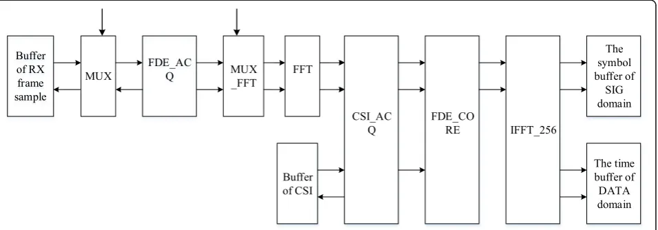
SC-FDE symbols in the time domain are read from “buffer of RX frame sample”by the channel equalization module and sent to the FFT module to calculate the fre-quency domain values of SC-FDE symbols.
Frequency domain values are read from “buffer of
CSI” by the CSI_ACQ module, which can complete the integration of corresponding samples meanwhile.
With the complex multiplication of the corresponding sample points completed by the FDE_CORE module, the frequency domain equalization is achieved.
Meanwhile, with the subsequent IFFT_256 module controlled by the FDE_CORE module, the sample points in the frequency domain after the equilibration are re-stored to the time domain and re-stored in the symbol buf-fer of SIG domain and the time bufbuf-fer of DATA domain, respectively.
The simulation results of the channel equilibrium based on the ModelSim platform are shown in Fig.10.
DataInRe and DataInIm are the real part and imaginary part of the input data, respectively. DataInEnable is the enable signal of input data. DataOutRe and DataOutIm are the real part and imaginary part of output data, respectively.
2.8 RS decoding
The design procedures of the RS decoder are as follows:
1. The adjoint polynomials(x) of RS codes is calculated from the receiving codes.
2. The error position polynomiala(x) and error value polynomialδ(x) are solved by an adjoint
polynomial.
3. The error position can be acquired by using the Chien searching method to calculate the roots of error location polynomials.
4. The error magnitude corresponding to each error location can be obtained from the error value polynomial by using the Fomey algorithm, namely C(x) =R(x)−E(x).
5. After decoding, the adjoint formula of the codeword is calculated again, and the adjoint formula is determined by detecting whether the adjoint formula is zero or not.
According to the above procedures, RS decoder should include four parts: the adjoint polynomial calculation module, the key equation solving module, the money search module, and the Fomey algorithm module [18].
Specific procedures of RS decoding design are as follows:
1. Solving the adjoint polynomial of RS decoding. The parameters of RS (255,191) are as follows:
Encoding length:n= 255 Information bit length:k= 191 Parity bit length: 64
Error correcting capability:t= 32 Primitive polynomial:
p xð Þ ¼x8þx4þx3þx2þx1þ1: ð25Þ The generating polynomial of RS (255,191) is as follows:
g xð Þ ¼x−a0x−a1x−a2Λx−a15: ð26Þ The RS is solved by using a, a2, a3,…, a32, in which R(x) =r0+r1x+r2x2+ …rn−1a(n−1). The 32
ad-joint expressions of RS (255,191) codes are acquired, namely s1, s2, s3,…, s32.
s xð Þ ¼X
2t
i¼1
sixi−1;si¼R ai ;ð1≤i≤2tÞsi
¼R ai ð27Þ 2. Solving the error position polynomial. Firstly, the error location polynomial δ(x) is obtained, then the error location polynomial and the error value polyno-mial are obtained. The error location polynopolyno-mial δ(x) can be defined as:
δð Þ ¼x ð1−θ1xÞð1−θ2xÞΛð1−θtxÞ: ð28Þ The error location isθ1.…θt. The right part of the
ex-pansion equation is simplified as follows:
δð Þ ¼x 1þðθ1þθ2þΛþθtÞx
þðθ1θ2þθ1θ3þΛþθt−1θtÞx2þΛ
þθ1θ2Λþθ1Þxt: ð29Þ The error location polynomial is acquired:
δð Þ ¼x 1þδ1xþδ1x2þΛþδ1xt: ð30Þ 3. Solving the error position. The error location of receiving polynomial R(x) =r0+r1x+Λ+rn−2xn−2+rn
−1xn−1is acquired according to the root of δ1x.
4. Ascertaining the error pattern E(x) and the polyno-mial of c(x). The error value polynomial is defined as follows:ω(x) =S(x)δ(x), which is simplified as follows:
ωð Þ ¼x s1xþðs2þδ1s1Þx2þΛ
þðstþδ1st−1þΛþδt−1s1Þxt
þðstþ1þδts1þΛþδ1s1Þxtþ1þΛ: ð31Þ The following equations can be verified.
st¼1þδ1stþΛþδts1¼0
stþ2þδ1stþΛþδts2¼0
s2tþδ1s2tþ1þΛþδtst¼0 ð32Þ The error value polynomialω(x) =ω1x+ω2x2+ωtxtcan be
obtained if ω1=s1, ω2=s2+δ1s1, Λ, ωt=st+δ1st−1+Λδt−
1s1. The error patternEðxÞ ¼
Pt
i¼1Yixtii can be obtained by
Yj¼
−xjωðx−j1Þ
δðx−1
jÞ . Here, xj is the root of the Chien searching method. The final actual codeC(x) is obtained withE(x) and the receiving codeR(x) superposed.
Fig. 11The simulation diagram 1 of the RS decoder. The output data of the decoders. The decoding results are shown
5. Calculating the adjoint formula of the codeword again. The decoding result is determined by detecting whether the adjoint formula is zero or not.
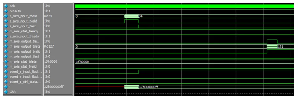
The RS decoding is implemented on FPGA. The simu-lation results are shown in Figs.11,12, and13.
As is shown in Figs. 11and 12, the output of RS en-coding is used as the input of RS deen-coding data. The in-put is as follows: (1, 2, 3, …, 190, 191, 204, 5, 85, 10, of RS decoding is the input of RS encoding, the output is correct. Namely, the output is (1, 2, 3, …, 190, 191). As is shown in Fig. 13, the RS decoding decodes the encoded data. The RS encoding is correct.
2.9 16QAM demodulation module
RS decoding is followed by the 16QAM demodula-tion. With the orthogonal coherent demodulation
method applied, the signal is judged, detected, and converted in series and parallel, and the final output is generated.
The expressions of demodulatedIbranch andQbranch are shown in Eq. (33).
output of 16QAM demodulation is obtained. The expression is as follows:
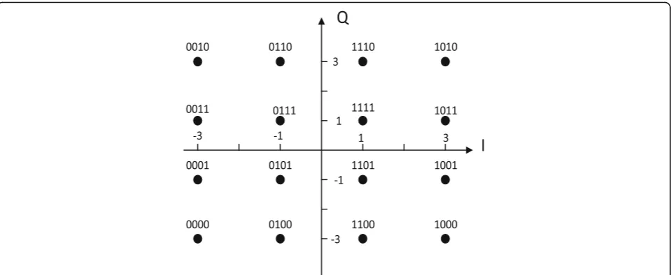
The constellation of the 16QAM modulation is shown in Fig.15, and its mapping output value isd= (I
Fig. 12The simulation diagram 2 of the RS decoder. The output data of the decoders. The output of RS encoding is used as the input of RS decoding data
+jQ) ×KMOD, whereKMOD¼1=
ffiffiffiffiffi 10 p
. The constellation of the 16QAM modulation is shown in Fig.14.
The I-way component and Q-way component cor-respond to b0 b1 and b2 b3 in the code elements
b0 b1 b2 b3, respectively. With the decision
thresholds set as −2 ×KMOD, 0 and 2 ×KMOD,
respect-ively, the I and Q can be demodulated now.
3 Experiment results and discussion
With the AD9361 used as the RF module, ZC706 ap-plied as the digital baseband processing module of SOC,
and ZC706 utilized as the ARM+FPGA framework, the hardware platform of the software radio system is built. The physical connection between AD9361 and ZC706 is
shown in Fig. 15. The AD9361 board card and the
ZYNQ ZC706 development board are connected by FMC. A spectrum analyzer is used as the tester of the transmitting and receiving terminals during the system test. The accuracy of the system test is evaluated by ob-serving the frequency spectra.
Joint testing is performed for the designed software radio receiver, which is based on the hardware platform of AD9361. The test framework of the receiving terminal
Fig. 14The constellation of the 16QAM modulation. TheI-way component andQ-way component correspond tob0 b1andb2 b3in the code
elementsb0 b1 b2 b3, respectively
is shown in Fig.16. The transmitting central frequency, transmit gain, and bandwidth are 1.435 GHz, 15 dB, and 20 MHz, respectively. AD9361 is connected to ZYNQ via FMC, and ZYNQ is connected to the spectrum analyzer via JTAG. The final results are displayed through the spectrum analyzer. The detailed procedure can be described as follows: signals are received, signals are inputted into AD9361 via the antenna, and these in-put signals are sent into the digital baseband processing module to complete the processing after amplification, mixing, filtering, and A/D conversion based on AD9361.
AD9361 is set as the working modes of 1R1T, LVDS, and TDD. The ADC frequency is set as 13 MHz, and the local frequency is set as 1.435 GHz, which can be dis-played through the spectrum analyzer. The frequency spectra at the receiving terminal are shown in Fig.17.
Joint testing is also performed for the transmitting sig-nals and the receiver, with the transmitting and receiving frequency spectra examined, which are shown in Fig.18.
As shown in Fig. 16, the transmitting frequency
spectrum is located in the upper position, while the re-ceiver frequency spectrum is located in the lower position. The overlapping of the frequency spectra of the transmit-ting signals and receiver indicates the consistency of pa-rameters between the transmitting and receiving signals. Therefore, transmitting signals are received accurately.
In this study, a joint experiment of RF module and digital baseband processing module is carried out. The experiment is carried out by two modules combined with a signal source and a spectrum analyzer. But there is no video display part and signal compression part, which can be added to the system to promote the appli-cations in our future research.
4 Conclusions
An AD9361-based software radio system was designed by using AD9361 as the hardware platform. The receiving
Fig. 16The test framework of the receiving terminal. The test framework of the receiving terminal. Joint testing is performed for the designed software radio receiver, which is based on the hardware platform of AD9361
function is realized, with the modules for group detection, frame synchronization, channel estimation, and frequency-domain equilibrium designed. Finally, the results of the software radio receiver were optimized and verified. The major conclusions from this study are as follows:
1. The single-carrier frequency domain equilibrium is applied on the digital baseband physical layer, which is optimized on the basis of the SC-FDE communi-cation protocol. Then, the receiving function on the basis of the software radio receiver is realized by using the optimized communication protocol. The system can effectively resist the frequency-selective fading of channels, thus achieving high-rate and large-capacity communication transmission. 2. Peak to average power ratio and the sensitivity to
the phase noise are decreased by the MMSE equilibrium algorithm, thus enhancing the resistance against multipath interference.
The AD9361-based software radio receiver presented in this study has a reasonable structure, and its performance indexes are satisfactory. The proposed system can effect-ively increase the communication speed and capacity, remarkably ameliorate the reduction of signal quality caused by multipath fading, and excellently offset the poor universality and expansibility of traditional radio receivers. The results of this study can serve as a useful reference in the development of next-generation uni-versal software radio receivers.
Abbreviations
FFT:Fast Fourier transform algorithm; FMC: FPGA Mezzanine Card; FPGA: Field programmable gate array; IF: Intermediate frequency; JTAG: Joint Test Action Group; MMSE: Minimum mean-squared error; MSE: Mean square error; QAM: Quadrature amplitude modulation; RF: Radio frequency; SC-FDE: Single-carrier frequency domain equalization; SNR: Signal-to-noise ratio; SOC: System on chip; SPI: Serial Peripheral Interface; TDMA: Time-division multiple address; UW: Unique words
Acknowledgements
This work was supported by the Project of Science and Technology of Shaanxi (No.2018GY-151).
Funding
This work was supported by the Project of Science and Technology of Shaanxi (No.2018GY-151).
Availability of data and materials
The authors declare that all the data and materials in this manuscript are available.
Authors’contributions
The contributions of all authors are equal in this manuscript, and all authors read and approved the final manuscript.
Authors’information
Feng Tian is currently an associate professor of College of Communication and Information Engineering, Xi’an University of Science and Technology. Hanqing Li is currently pursuing an MS degree at the College of
Communication and Information Engineering, Xi’an University of Science and Technology.
Liangchen Yuan is currently pursuing an MS degree at the College of Communication and Information Engineering, Xi’an University of Science and Technology.
Competing interests
Publisher’s Note
Springer Nature remains neutral with regard to jurisdictional claims in published maps and institutional affiliations.
Received: 14 January 2019 Accepted: 28 March 2019
References
1. C. Andrews, A passive mixer-first receiver with digitally controlled and widely tunable RF interface. IEEE J. Solid State Circuits45(12), 2696–2708 (2010).https://doi.org/10.1109/JSSC.2010.2077151
2. H. Darabi, D. Murphy, M. Mikhemar, H. Wu,2.1 A Highly Linear Inductor Less Wideband Receiver with Phase- and Thermal-Noise Cancellation(IEEE International Solid-State Circuits Conference, San Francisco, 2015), pp. 1–3.
https://doi.org/10.1109/ISSCC.2015.7062850
3. L. Yang, Z. Zhang, W. Hou, B. Zhao, H. Zheng, Papyrus: a software platform for distributed dynamic spectrum sharing using SDRs. ACM SIGCOMM Computer Communication Review41(1), 32–37 (2017).https://doi.org/10. 1145/1925861.1925866
4. C.J. Loubser, T.G. Swart,Cognitive Radio DAB MAC Protocol Performance Using a CR Specific Simulator and Software Defined Radio(IEEE AFRICON, Cape Town, 2017), pp. 139–144.https://doi.org/10.1109/AFRCON.2017.8095470
5. A. Kamaleldin, S. Hosny, K. Mohamed, M. Gamal, A. Hussien, E. Elnader, A. Shalash, A.M. Obeid, Y. Ismail, H. Mostafa,A Reconfigurable Hardware Platform Implementation for Software Defined Radio Using Dynamic Partial Reconfiguration on Xilinx Zynq FPGA(2017 IEEE 60th International Midwest Symposium on Circuits and Systems (MWSCAS), Boston, 2017), pp. 1540– 1543.https://doi.org/10.1109/MWSCAS.2017.8053229
6. A. Marwanto, S.K.S. Yusof, M.H. Satria, Orthogonal frequency-division multiplexing-based cooperative spectrum sensing for cognitive radio networks. Telkomnika (Telecomm Comput Electron Contr)12(1), 143–152 (2014).https://doi.org/10.12928/TELKOMNIKA.v12i1.310
7. R. Srinivasa, S. Kotha, S. Kumar, An approach for fixed coefficient RNS-based FIR filter. Int. J. Electron., 1–19 (2017).https://doi.org/10.1080/00207217.2017.1296593
8. X. Qin, L. Wang, H. Zhao, Y. Deng, Realization of spectrum sensing based on MATLAB and general software radio peripherals. Comput. Eng.41(5), 106– 110 (2015)
9. S. Xu, Z. Yu, K. Chang, Y. Wu, B. L, Design and implementation of fault prediction software for airborne software radio system. Meas Contr Technol
35(8), 111–114 (2016).https://doi.org/10.3969/j.issn.1000-8829.2016.08.028
10. Z. Cui, Design of frequency hopping communication terminal based on software radio principle. Modern Navigation8(5), 365–371 (2017) 11. Y. Zhang, X. Cui, T. Da, G. Wang, Design of GNSS jamming and multipath
monitoring system based on software radio. Telecommun. Eng.57(3), 288– 295 (2017)
12. Z. Yin, L. Cheng, Design of low power software radio platform based on ZYNQ7000. Wireless Internet Technol37(3), 31–32 (2018)
13. M. Mishra, A. Potnis, P. Dwivedy, S.K. Meena,Software Defined Radio Based Receivers Using RTL—SDR: a Review(2017 International Conference on Recent Innovations in Signal processing and Embedded Systems (RISE), Bhopal, 2017), pp. 62–65.https://doi.org/10.1109/RISE.2017.8378125
14. Y. Qi, X. Chen, Z. Xie, S. Yuan,An Improved MMSE-RISIC Equalization Algorithm Based on STBC-SC-FDE(2018 IEEE 3rd International Conference on Signal and Image Processing (ICSIP), Shenzhen, 2018), pp. 310–314.https:// doi.org/10.1109/SIPROCESS.2018.8600476
15. K. Kumar, S. Pillai, S. Sagar, S.K. Parambeth, N. Prem Krishnan,Implementation of Digital Pre-Distortion for Power Amplifier Linearisation in Software Defined Radio(Twenty-third National Conference on Communications (NCC), Chennai, 2017), pp. 1–6
16. J. David Cepeda, S.I. Rodríguez, M. Rico-Martínez, C. Daniel Muñoz, M. Varón, I.T. Monroy,Performance Evaluation of a Real Time OFDM Radio over Fiber System at 2.5 GHz Using Software Defined Radio SDR(SBMO. IEEE MTT-S International Microwave and Optoelectronics Conference (IMOC), 2017), pp. 1–5.https://doi.org/10.1109/IMOC.2017.8121094
17. E. Balevi, A.Ö. Yιlmaz, Analysis of frequency domain oversampled MMSE SC-FDE. IEEE Commun. Lett.20(2), 232–235 (2016)