Abstract
In this work, we propose a closed-loop analog system to detect the source information of a binary data stream coded by a flexible finite automaton. We initially consider the dual sideband suppressed-carrier modulation of a base band binary amplitude waveform. The automaton introduces a symbol redundancy as phase contribution of the
modulated signal by a simple mapping scheme. The proposed recovery system performs a coherent demodulation, presenting the base-band binary wave to a maximum likelihood hard detector, a simple analog trigger that estimates the source data within the symbol period. This wave is over-sampled, and the final decision comes by counting the positive samples and a majority vote. We prove our approach is valid answering the most important concerns: the stability of the closed loop, a first analytical expression of the error rate when a Markov birth process models the counting phase, and finally the role of this last loop to lower the bit error rate compared to a simple Costas loop. The analysis continues by solving the problem of carrier and symbol rate recovery and the impact of non-linearity and noise in the basic analog blocks. Behavioral simulations describe a competitive scenario in terms of error rate, comparing the proposed approach to the Costas Loop and the basic convolutional decoding strategies based on Viterbi algorithm both in the hard (Hamming metrics) and soft (Euclidean metrics) versions.
Keywords: Closed loop system, Decoding, Error analysis, Finite automata’s theory, Stability analysis, Viterbi algorithm
1 Introduction
The need for efficient utilization of the radio channel under additive and multiplicative noise sources has stim-ulated the investigation of advanced digital modulations and coding techniques. Because highly stable oscillators are available for practical applications, it has been possi-ble to detect digital phase-modulated signals, and in these 60 years, there are many developed communication sys-tems with such modulation. Furthermore, coding theory increases the error-correcting capability of transmitted information by symbol redundancy, requiring more band-width for the complete demodulation and decoding [1]. Maximum likelihood (ML) and maximum a posteriori probability (MAP) [2] detection methods require the log-likelihood ratio (LLR) computation, which is hardware expensive for energy-constrained applications [3]. The problem of area reduction in electronic systems concerns about cost of silicon wafers, and therefore, it has an eco-nomic impact. Instead, low-power dissipation affects the
Correspondence:[email protected],[email protected] Independent Researcher, Messina, Via delle Mura, 44, Messina, Italy
prolonging of system lifetime of battery-operated devices such as wireless sensor networks, implantable devices, radio frequency identification, and much more. However, low-power CMOS and radio frequency (RF) design is not exclusively for portable systems; today, reducing power dissipation in electronic circuits is a mandatory target in consumer, industrial, space, and military applications [4].
The relative simple characterization of a digital com-munication system is an important advantage over ana-log communication, where there are many more ways to degrade a transmission. Analog decoding systems have gained many interests in the research community since the contributions by Hagenauer [5] and Loeliger et. al
[6]. The main advantages are the extremely low-power
dissipation and a faster ML algorithm execution up to 1000 times than a common digital signal processor (DSP). This approach uses bipolar transistors and diodes, which realize the exponential and logarithmic function respec-tively [7]. These basic components calculate the log-likelihood ratio as a main operation in the detection theory. There are in the recent literature some industrial applications [8–10] that uses the analog decoder, although
process variability and device mismatches are the most important drawbacks that affect the precision of LLR estimation [11].
In this work, we search an alternate way to recover a binary information from the modulated waveform that
does not need the LLR computation [12]. The related
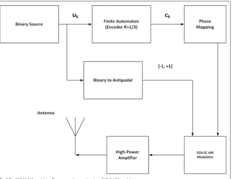
hardware therefore is well suited for the used modula-tion, and we expect some difficulties to consider different waves for the same system. We extend the application of recovery loops used mainly in digital transmission over a serial link [13, 14] (e.g., cable) to the radio frequency domain. Test cases debug, when using a 1/3 rate convo-lutional code [15] and a double sideband suppressed car-rier amplitude modulation (DSB-SC AM), indicated the encoder output matrix and a symmetric phase mapping as responsible of poor error performance. Consequently, we consider the flexible finite automata where loop sta-ble points may correspond, by properly settings, to the correct decoding. The amplitude modulation (AM) part of the used modulated waveform is an antipodal binary base-band signal, mapping the information bit (0, 1) to uk ∈(−1,+1). Equation (1) shows our former pass-band waveform in the current time interval [kT,(k+1)T],kis the discrete time step andTis the symbol period;f0is the
carrier frequency, andθ0the initial phase.
s(t)=Es·uk·cos
2·π·f0·t+θk+θ0
(1)
This wave is functionally equivalent to the well-known trellis code modulation (TCM) illustrated in [16–18] and measured as engineering unit (EU). The variableEsis the signal’s energy measured in joule. The finite automaton receives the binary information, generating the code word ck; Eq. (2) shows our used mapping scheme to calculate the contributionθkin (1).
θk = 2·π
M ·ck (2)
The variableMrepresents the mapping order as the num-ber of allowed symmetric phases. The automaton has rate
1/R such that M = 2R. The proposed recovery loop
receives the signal (1) corrupted by a pass-band additive
white Gaussian noise (AWGN) [19]. A proper coherent
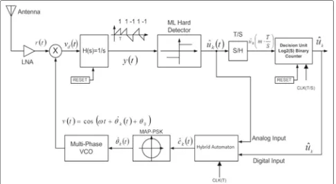
demodulation by a multi-phase voltage-controlled oscil-lator (MP-VCO), a mixer, and finally a loop filter applies to a simple ML hard detector (e.g., a trigger [20]), the amplitude signal corrupted by a base-band additive white Gaussian noise. The trigger’s output is an analog estima-tion within the current symbol interval [kT,(k +1)T]. Finally, the decoded source symbol is chosen collecting the positive samples at rate T/S where S is generally a power of two; the current output is 1 if the counter is greater than or equal to S/2 otherwise0.
The loop’s role is to electrically remove the cosine in (1), so it is composed by a mixer, an MP-VCO at frequency
f0and initial phaseθv, a loop filter with Laplace function H(s), and a copy of the used finite automaton to generate the current estimated phaseθˆk(t). Since finite automata are discrete-time linear time-invariant (LTI) systems, it is impossible to track the current phase in the analog domain. We solve this apparent problem by using a hybrid finite automaton [21], where the output network works in the continuous time domain, receiving the source sym-bol’s analog estimation and tracking the current code word. The internal state update network works in the discrete-time domain, receiving the final estimation at the current time step, preparing the hardware to decode the next symbol.
We analyze the Costas loop as our reference approach, completed internally by a mechanism of triggering, sam-pling, and finally a majority vote. We include also the Viterbi algorithms of a M-ary phase shift keying (M-PSK) modulation and a convolutional encoder as additional benchmarks. We use the SystemC/SystemC-AMS class library to model these systems in the scenario of a point-to-point link over AWGN channel. The loop’s bit error rate (BER) is better than our reference system working with perfect phase and timing recovery. Next, we sim-ulate the recovery loop when the carrier’s initial phase and the timing reference introduce a jitter. After, we include the effects of non-linearity, in the mixer and the phase noise [22] in the MP-VCO. Typical architectures of high-frequency MP-VCO use a closed loop of elemen-tary voltage-controlled oscillator (VCO) as shown in the contributions [23] and [24].
The paper has this organization. We analyze in depth the behavior and the necessary conditions for the com-plete feasibility of our solution in Section 2. We illus-trate in details the structure and the behavior of our solution. Section 3 tackles the noiseless stability of the closed loop, followed by a first analytical expression
of the bit error rate in Section 4, this last when a
Markov chain models the counting process. Section 5
addresses the problem of phase and timing recovery.
Section 6 shows our conducted simulations. Finally, we
consider the single-sideband suppressed-carrier ampli-tude modulation (SSB-SC AM), which introduces ideally a spectrum efficiency of 100%. Our conclusions under-line the importance of this approach and a considera-tion of the main telecommunicaconsidera-tion problems as future directions.
2 Proposed implementation method
is the rectangular function in [0,T] and a final amplifier drives the transmitter antenna.
Figure 2 shows the proposed coded symbol recovery
loop using oversampling. The antenna receives the wave (1) scaled by the channel attenuation and corrupted by a AWGN noise. The low-noise amplifier (LNA) magni-fies the signal-to-noise ratio (SNR) presenting the DSB-SC AM signal to the demodulation section. We assume the LNA is an ideal band-pass filter, with the flat spectrum in the considered bandwidth. The proposed loop uses a mixer, modeled originally as a simple ideal multiplier, a MP-VCO that receives the current code word estimation
in the Eq. (4). Ifn(t) is the base-band additive white Gaus-sian noise and the differential phasek(t) = θk − ˆθk(t), we have at the loop filter’s output, modeled as a simple integrator (1/s), this waveform:
y(t)=0.5·Es·uk·(t/T)·cos(k)+
+n(t)
H(s)= 1 sT
(4)
The letter sin lowercase is the Laplace’s variable. We consider in this work a single-pole low-pass filter (LPF). Letfpbe the filter’s pole measured in hertz andω=2.0·
Fig. 2The proposed coded symbol recovery loop using oversampling. This mixed-signal system recovers the source data by analog estimation,
Noise model at the antenna is a band-pass zero-mean additive Gaussian random process with two-sided power spectral density N0/2 measured in watt/hertz. Noise ran-dom processn(t) in (5) is low-pass and zero-mean
Gaus-Figure3shows the loop filter’s output under the models (4) and (5); the integrator generates positive and negative ramps; instead, the one-pole low-pass filter generates exponential smoothing. A deterministic finite automaton (DFA) is represented by digraph called state diagram. In fact, a DFA can be represented by a 7-tuple (Q,,δ,q0,F,
- O is a finite set of symbols called the output alphabet. - X is the output transition function:X:Q×→O.
The sethas two elements(−1,+1), instead the output alphabetOhasMdifferent valuesck ∈[ 0, 1,. . .,M−1]. We use a flexible finite automaton instead of a convolu-tional code, to have the freedom for the proper selection of the output alphabetOand the output transition function X. A preliminary noiseless stability analysis discussed later drove these final values for theXfunction in (7). A ran-dom output alphabet may cause oscillations due to loop instabilities and unacceptable global error rate. The car-dinality ofQis eight andδ and X are two matrices with eight rows and two columns. The output values inXlimit the possible differential phasek, when the two automata have the same internal state, to two different values: zero (loop is in-lock) and 2π/M(loop out-of-lock).
Fig. 3Loop filter’s output: low-pass (top) and integrator (down). The filter’s output is a continuous function in the current time interval with the polarity aligned to the antipodal source symbol. The threshold for ML detection is zero
In Eqs. (4) and (5), when the receiver is in the in-lock state, the differential phase is zero, so the ML hard detec-tor (trigger) estimates the source symbol at the minimum error probability:
ˆ
uk(t)=sign(y(t)) (8)
When the differential phase is in the interval [π/2, 3π/2], the cosine is negative so the wrong decision event improves its probability. This simple issue suggests an
implementation of the automaton output function X,
avoiding the cosine negative. The choice (7) satisfies this criterion under the hypothesis the two automata (in the transmitter and the recovery loop) have the same internal state. We see later the cosine positive matches the loop’s noiseless stability criterion. The sample and hold (S/H) samples the analog estimation (8) at rateT/S. Finally, a
log2(S) binary counter counts the positive samples, and
a final decision uˆk is majority vote-based. This theory applies to a binary and identically distributed source sym-bols. An important point, Viterbi decoders deliver the output-estimated source symbol with a delay proportional to the depth of traceback path; the proposed recovery loop estimates the source symbol always with one symbol delay (T).
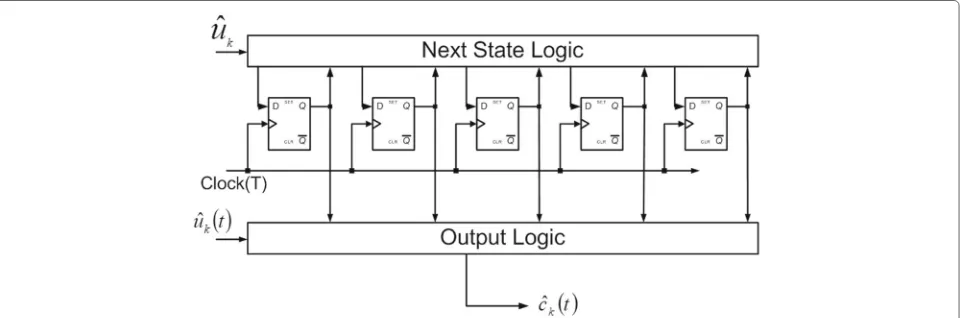
The hybrid automaton uses the final decision uˆk to update its internal state (Q), preparing the recovery loop for the next decoding. Figure4 shows a possible imple-mentation of the hybrid automaton based on D-type flip-flop and combinational logic. Hereafter, we call this blockhybrid encoder. Finally, the proposed analog system requires a form of synchronization; the hybrid encoder receives the clock rate T; instead, the counter receives
a clock at higher frequencyS-time (T/S). Additionally, a reset pulse with periodTand duty cycle 1/S, at the begin-ning of the current symbol period, puts all the subsystems with memory in a known initial state. It clears the internal counters, the hybrid encoder, and the loop filter internal states.
3 The noiseless stability analysis
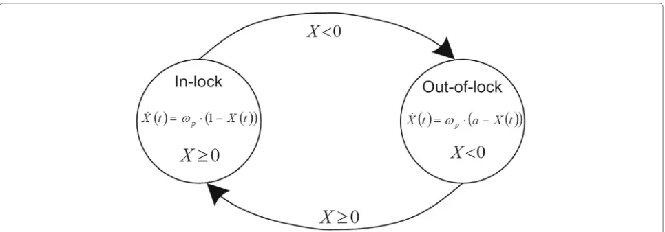
The proposed recovery system uses the analog loop to track the current phase code word, applying the AM section of the supported modulation to an ideal ML hard detector, a simple trigger. For this reason, stability repre-sents one of the most important concern for the concrete deployment of such system. In this section, we tackle the problem of loop’s stability demonstrating, under specific hypothesis, the correct decoding is a stable point for the whole system. We analyze the stability of the proposed loop by removing the effect of the AWGN noise and mod-eling the analog loop by a switching system made of the mixer, the loop filter, the ML hard detector, and finally the analog path of the hybrid encoder. Figure5shows this hypothetical equivalent description of the tracking pro-cess. Letx(t) be the loop filter’s internal state under the model (5) and y(t)=x(t), so the switching system allows these constituent equations:
f1(x)= −ωp·x+ωp·uk x≥0
f2(x)= −ωp·x+a·ωp·uk x<0 (9) In (9), we replaced the cosine with a generic variablea which is either positive or negative. The Lyapunov stabil-ity criterion for the single equation in (9) is not a sufficient condition for the stability of the whole switching system [25,26]. Letukbe 1 for simplicity; equilibrium points are calculated by placing x˙ = fi(x) = 0,i = 1, 2 in both equations in (9) so they are:
x1eq=1 x2eq=a (10)
When ais positive, the correct detection is the unique equilibrium point; instead, if the variable is negative, the wrong detection and therefore the out-of-lock internal state is an additional equilibrium point. Lastly, we con-clude the cosine of phase difference must be positive for the stability of the whole system. This result implies the correct selection of the automata output transition func-tion (X); the choice (7) matches our stability condition. A positive cosine and the phase mapping in (2) imply the transmitted (ck) and received (ˆck(t)) code words to be:
−M
4 <cˆk(t)−ck < M
4 ∀k,t∈ {kT,(k+1)T} (11) This last result justifies the use of a flexible automaton instead of a convolutional or turbo code [27,28]. As a con-sequence of Eq. (11), a stable loop that supportsMgeneric different symmetric phases, similarly to (7), has the output
transition matrixX where in each row the two possible
valuesxi,1andxi,2generate a positive cosine.
X:
The matrixXtherefore matches for any row the following formula:
The recovery loop with two symmetrical phases (M= 2)
has the wrong detection as an additional equilibrium point. If our loop supports four symmetric phases (M= 4), the stability point zero is not an additional equilibrium point for this switching system. However, this choice implies the highest out-of-lock probability responsible of an unaccetable global error rate. So,M= 8 is the minimum for the concrete deployment of our solution.
4 The lower bound analytical bit error rate A secondary goal, in the analysis of the proposed recovery loop, is to compare the BER from behavioral simulations with a predicted model. The detection algorithm, after a preliminary coherent demodulation, is mainly a counting process, analyzing the positive samples of (8). For this rea-son, a Markov chain and the specialization to a pure birth process represent the optimal mathematical description. For the loop state (in-lock or out-of-lock), we consider a two-state Markov chain. The internal states S0 and S1 represents the in-lock and out-of-lock value respectively. In this section, we approximate the single-pole loop fil-ter’s step function with a series of rectangular pulses, a phase mapping with eight different values (M= 8), and the phase differencek(t)aligned to the model (7). The equations below describe the sampled wave at the trigger’s input when the loop is in-lock or out-of-lock.
Fig. 5The closed-loop mathematical model as switched system. The loop is stable when the correct detection is the unique statistical equilibrium
The term Qf is the cumulative distribution function of the standardized normal random variable. We solve the Chapman-Kolomogrov equations for the stationary dis-tribution, deriving the in-lock probability PL such as :
PL=P(S0)= 1
1+ pq (17)
The decision unit is a binary counter, so we use aS-state pure birth process. We identify four different scenarios that correspond four different transition probabilitiesλ:
. E0 is loop in-lock and source symbol positive. . E1 is loop out-lock and source symbol positive. . E2 is loop in-lock and source symbol negative. . E3 is loop out-lock and source symbol negative.
We specialized the model (14) in these four different scenarios, deriving four birth rates as the probability λEi=PR{ym>0|Ei}:
The binary counter receivesS clock impulses, so BER is the result of the chain’s stochastic model at stepS. LetC be the counter value afterSsteps; the approximate error rate is therefore:
BER≈0.5·((PR{C<S/2|E0}+
+PR{C≥S/2|E2})·PL+(PR{C<S/2|E1}+
+PR{C≥S/2|E3})·(1−PL))
(19)
Conditional probabilities in (19) require the counter’s stochastic model:
PR{C<S/2|Ei} =nS/=20−1PR{C=n|Ei}
PR{C≥S/2|Ei} =Sn−=1S/2PR{C=n|Ei}
(20)
This error rate assumes the used finite automata aligned at current discrete time step; for this reason, we expect the proposed number is a lower bound. The use of four
symmetric phase (M = 4) makes the highest value of
probability (16) to 0.5. Additionally,M=4 influences the in-lock probability in (17) and the profile of the four birth rates showed in (18) . Globally, the statistical effects of M=4, although there are no oscillations in the noiseless switched system, are the highest bit error rate.
5 Phase and timing recovery
sequence allows phase alignment between the transmit-ter oscillator and the MP-VCO. Symbol timing recovery is a combination of a proper selection of the pilot sequence and use of a known hardware since the 70s [29,30] based on a closed-loop made of a digital phase detector, an ana-log loop-filter, a VCO oscillator and finally a frequency divider. We transmit a repeated and periodic sequence+1 and−1 to realize a clock at frequency 1/2T. This refer-ence pulse has the same transmitter clock’s internal phase. LetL(s) be the Laplace function of this loop filter; it is a one-pole filter where we set these important constraints: ωF=2πfF,fF·T>>1 andKFstrictly positive:
L(s)=KF· ωF
s+ωF
(21)
Timing jitter jk at stepk is a function of the loop filter direct current (DC) gainKF and the VCO sensitivityK0.
The output of the digital phase detector is a rectangular pulse within the timing interval [kT,(k+1)T] with ampli-tudejk−1. Therefore, letI(s) be the Laplace function of the
impulse according to the equation below:
I(s)= 1 s ·
1−e−s·jk−1·e−s·τ0 (22)
We assumed for simplicity the delayτ0 = 0. Let u(t) be
the step function, the loop filter output wavef(t) uses the functionαdefined as:
α(t)=u(t)·1.0−e−ωF·t≈u(t) (23)
Under these approximations, the functionf(t) is therefore:
f(t)=KF·u(t)−KF·u(t−jk−1) (24)
The digital VCO uses the functionf(t) as follows:
jk=jk−1−K0·KF·
Therefore, jitter afterN pilot symbols is a function of related initial valuej0:
jN =j0·(1−K0·KF)N (26)
The proposed loop achieves the clock phase tracking until the perfect timing recovery. Phase recovery uses the same pilot sequence; now the MP-VCO generates a new wave-form with the pilot symbol, the related code word, and further phase rotation ofπ/2, resulting the sine function according to the equation below:
v(t)=Es·uk·sin
2·π·f0·t+θk+θv+θA
(27)
The MP-VCOs indicated in the first section have diffi-culties to generate the signal (27). The contribution [31]
shows a MP-VCO realized with a daisy chain ofM
dif-ferential and tunable (in frequency) VCOs. This phase generator works at high frequency with a low-phase noise.
The M VCOs generate the digital phasesθk, instead the tune port receives a signal proportional to the derivative of the ML triggery(t) to achieve the phase recovery. Gener-ally, a frequency tunable VCO allows the carrier recovery. A small varactor can be used in combination with MOS transistors that switch a fixed capacitor in and out of the VCO as suggested in [32]. This approach allows the large tuning ranges, reducing the translation of different scale in signal and noise to phase noise and sidebands. This VCO, therefore, mitigates the tuning sensitivity, reducing the disturbances to the signal voltage and reducing the sen-sitivity to noise. Polyphase filters receive the tuned VCO output, generating the requiredMsymmetric phases [33]. Now, the signal after the mixer is a composition of two waveforms: the sine at frequency twice, removed by the loop filter, and the sine of differential phase, so the signal y(t) under the model (4) is therefore:
y(t)=Es·(t/T)·sin(θ0−θv−θA)+n(t) (28) The additional phaseθAis the result of a closed loop with the signal (28) and a VCO with sensitivityKv > 0. The equation below shows the accumulated phase in the VCO:
θA=Kv t
0
y(τ)dτ (29)
At the end of the pilot sequence, the phaseθAachieves the carrier recovery:θA=θ0−θv.
6 Results and discussion
We prove the validity of our assumption, simulating the proposed decoder by a mathematical description using
System C/System C-AMS C++ library. Assuming no
inter-symbol interference and perfect knowledge of car-rier frequency and symbol timing, carcar-rier frequency is f0=400 Mhz,Es=1 J and the symbol rate isT =80 ns;
LNA bandwidth isB = 2 Mhz, and the loop filter cutoff
frequency isfp=20 Mhz.
6.1 Error rate comparing the proposed recovery loop with known digital and analog approaches
Our preliminary goal is to demonstrate the proposed closed-loop recovery system, jointly to the supported modulation, has better error rate with respect to other
radio frequency architectures. Figure6 shows our main
competitor to recover data without the LLR computation; it does not require any coding scheme. Costas’ loop uses a binary phase shift keying (B-PSK) digital modulation; it has also an ML hard decision unit, an oversampling mech-anism, and a unit for the majority-vote decision. In this way, the proposed circuit and the Costas loop apply the same modulation at the ML trigger. Additionally, our loop and the reference Costas recovery system have the same
over-sample rate: S = 8. Although the figure does not
Fig. 6The Costas loop as our reference oversampling data recovery system. This loop and the proposed recovery system have the same modulation at the ML trigger’s input
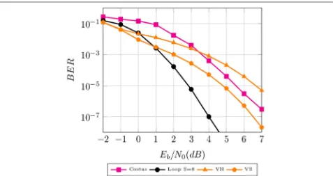
a low-noise amplifier, same carrier frequency, and sym-bol rate. We consider our mixed-signal system, the Costas loop, Viterbi hard (VH), and Viterbi soft (VS); these two last with 8-state internal trellis, a VLSI architecture that uses a traceback path with depth equal to 10 and 8-PSK
modulation. Figure 7 shows how our approach is
com-petitive over the state of the art in digital convolutional decoding. Our recovery loop gains more than 1 dB in signal-to-noise ratio with soft Viterbi when BER is 10−4. Additionally, the SNR gain reaches 2.5 dB comparing to the Costas loop at the same error rate. Furthermore, we also confirm the use of a DSB-SC AM modulation (equiv-alent to the trellis code modulation) has many benefits, such as same bandwidth of an uncoded phase shift keying
(PSK), improved bandwidth efficiency, and lastly high coding gain without compromising bandwidth efficiency or reduction of data rate.
6.2 Performance estimation using the lower bound
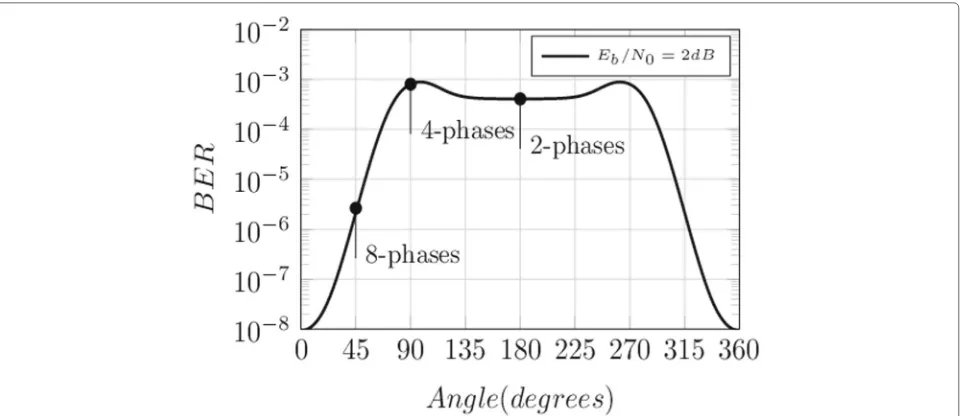
Our secondary goal is to demonstrate high-order phase mapping achieves the best error probability. For this
pur-pose, we use the lower bound found in Section4, when
SNR is 2 dB, varying the parameterkfrom 0 to 360°. The results are in Fig.8, where the error rate using eight dis-tinct phases is lower than two or four symmetric phases. However, higherMsignificantly improves the error rate. Figure9shows the error rate of the proposed closed-loop system (loopS=8) and lower bound bit error rates when
Fig. 8Analytical BER varying the parameterk(degrees). Higher phase mappings allow better error rate
sampling rate isS=8 (loop boundS=8) andS=16 (loop boundS=16) respectively. Analytical error bound sug-gests wrongly that we can improve the error probability with no limit increasing the over-sample rate (S). Instead, this limit arises in receiver physical design: the decision unit, a pure digital system at clock T/S, the sample and hold’s latency, the trigger’s bandwidth, and more. Figure9 also shows the Costas loop analytical BER from (19) when
PL = 1.0 and a context of B-PSK modulation. An
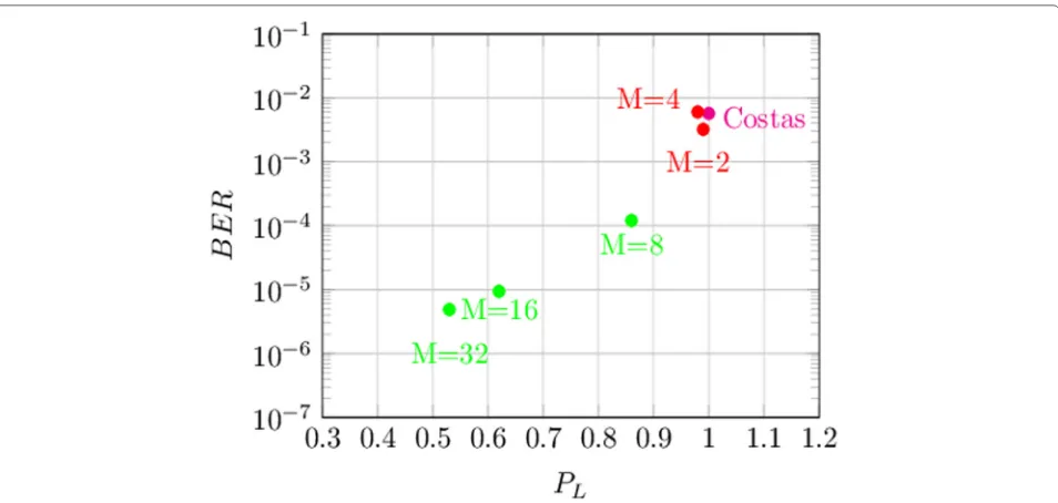
accu-rate analysis of the lower bound BER in Eq. (19) is shown in Fig.10when SNR is 0 dB. We found the presence of a loop with an in-lock probability (PL) less than 1.0 lowers the total error rate although the Costas loop removes the second half of the Eq. (19). Table1reports in detail the two contributions of BER: P1 linked to the in-lock probability and P2 linked to the coefficient(1.0−PL).
Fig. 10Error rate of Costas’ loop and some recovery loops varying the parameterMwhen Eb/N0 = 0 dB. The presence of an analog loop lowers the in-lock probability PL and optimizes the error rate than Costas’ approach
P1=(PR{C<S/2|E0} +PR{C≥S/2|E2})·
·PL
P2=(PR{C<S/2|E1} +PR{C≥S/2|E3})·
·(1−PL)
(30)
SNR is 0 dB and the term P2 dominates the lower bound BER when using our recovery loop. Instead, P1 is higher in the Costas loop, since the signal-to-noise ratio is aligned to a B-PSK modulation.
6.3 Effects of phase and clock jitter
This subsection shows the performance of phase and
clock recovery sub-systems. We sendN = 64 pilot
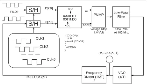
sym-bols, alternating the binary values 0 and 1. The timing recovery sub-system is a specialization of the hardware introduced in Section 5 and illustrated in Fig.11. This
Table 1Lower bound BER as the sum of two contributions varying M. SNR = 0 dB
M PL P1 P2 BER
Costas 1.0 0.0057 0.00 0.0057
2 0.99 3.90e−6 0.0032 0.0032
4 0.98 3.90e−6 0.0060 0.0060
8 0.86 3.42e−6 1.21e−4 1.24e−4
16 0.62 2.49e−6 6.99e−6 9.48e−6
32 0.53 2.11e−6 2.76e−6 4.88e−6
∞ 0.50 1.98e−6 1.98e−6 3.97e−6
hardware is a closed loop made of a phase detector, a voltage pump, a low-pass filter, a VCO, and finally a fre-quency divider by 2. In particular, the phase detector gains a binary data for both the pilot sequence and the RX side clock, sampling these waveforms at clock 1/8T, by using eight different clocks , CLK1, CLK2, ..., CLK8. Moreover, the digital phase detector measures the leading one of the two 8-bit registers at the CLK8-positive edge: P[7:0] (linked to the pilot sequence) and C[7:0] (linked to the RX oscillation), starting from the most significant bit (MSB) to the least significant bit (LSB) deriving two numbers CP and CC respectively. When CC< CP, the positive edge of the RX clock anticipates the positive edge of the pilot sequence so the pump receives an impulse to increase the voltage at the loop filter input. When CC> CP, the pump receives the command to decrease the output value. Finally, when CP=CC the two waveforms are aligned in phase, the pump clears the output value, and the VCO runs with the final offset, acquiring the timing recovery. We simulate with voltage step of 1.0 V for the analog pump, a loop filter with pole at 100 Mhz and a VCO with sensitivityK0such thatKF·K0= 0.052. This sub-system
gains the timing recovery with a relative jitter of 1.05% starting from an initial timing delay of 20 ns when the master clock has delay of 80 ns.
Next, we compare our phase recovery strategy with the Cramer-Rao bound (CRB); it is a lower bound for the vari-ance of any unbiased estimator under the optimal, in the log-likelihood sense, estimation theory. Under an hypoth-esis of a linear transformation s[k;θ0] over an AWGN noise
Fig. 11The timing recovery subsystem based on a digital closed loop. This architecture uses a phase detector that samples the pilot sequence and the RX clock. The leading one in the 8-bit registers measures the current jitter between these two waveforms
modified Cramer-Rao bound (MCRB) introduced in [34]
and [35]. Our bound considersN =64independentpilot symbols and N samples of the signal models s[k;θ0], so
the estimation of the initial phaseθˆ0introduces a variance
with a lower limit of:
Var{ ˆθ0} ≥ σ 2
N−1
k=0
∂s[k;θ0]
∂θ0
2 ≥
≥ 1
2·N·Es/N0
(31)
The real transformation is not linear since
s[k;θ0] = cos(θ0− ˆθ0)+nk; then, we can estimate the initial phase with a variance less then the number found in (31). We measure the error variance in degrees2, at the SNR range from 0 to 10 dB. We consider two different experi-ments where the phase recovery sub-system works with a product among symbol rateT, the loop filter DC gain andKvin (29) 0.028 (KV1) and 0.284 (KV2) respectively.
Figure 12shows how the scenario KV2 has better
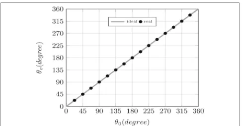
per-formance than the bound (31). At high SNR, our carrier recovery algorithm introduces an asymptote. The authors in [36] underline how the use of PS only and the lack of data symbols (DS) in the carrier recovery algorithm is the reason for the poor performance we found at high SNR. Finally, Fig.13shows the efficacy of the proposed phase
acquisition subsystem, under the model KV2, when the initial phase in (1) covers the full range in 0 to 360° and
the SNR=2 dB. Instead, Fig.14shows the performance
of our timing recovery algorithm measuring the relative final jitter varying the filter’s DC gain and VCO sensitivity
product whenN=64.
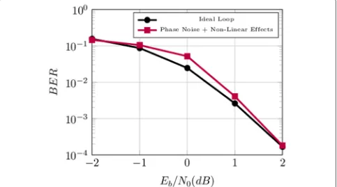
6.4 Effects of non-linearity and noise in the critical blocks
Effects of non-ideal modeling of critical block worsen the total bit error rate. For instance, the mixer is not an ideal four-quadrant multiplier; it introduces non- linearity and bias effects according to the model below for low carrier frequency [37]:
vd(t)=VOO+Km·(r(t)+VIO)·(v(t)+VIO) (32)
Fig. 12Performance of our carrier recovery sub system. Estimated phase’s variance analyzing two different scenarios
are shown in Fig. 15where we measure a SNR loss of
0.3 dB when BER is 10−2.
6.5 Use of SSB-SC AM modulation
In this work, we use the DSB-SC AM modulation to trans-mit information from the source to the destination, this last a mixed-signal recovery loop using oversampling. The AM signal ism(t)=Nk=−01mk(t)=
N−1
k=0 uk·p(t−kT).
The same hardware could be used to recover the source symbol from an SSB-SC AM modulation, with a better spectral efficiency than the dual sideband signal. There-fore, the analytic representationma(t)uses the message
m(t) and its Hilbert transform mˆ (t) = kN=−01mˆk(t) (j represents the imaginary unit):
ma(t)=m(t)+j· ˆm(t) (33)
Fig. 14Convergence of our symbol timing recovery sub-system. We plot the final relative jitter, whenN= 64, varying the filter DC gain and VCO sensitivity product, SNR = 2 dB
The SSB-SC AM waveform, in the current interval [kT,(k+1)T], is therefore:
sSSB(t)=
ES·mk(t)·cos
2·π·f0·t+θk+θ0
+ −ES· ˆmk(t)·sin
2·π·f0·t+θk+θ0
(34)
The process of frequency conversion is ideally the
mul-tiplication of signal (34), corrupted by AWGN noise,
with the MP-VCO output (3). After the mixer, we have
four components: the cosine and sine at frequency twice, removed by our loop filter, and finally the sine and cosine with the differential phasek. The effect of a real behavior
BER performance and stability issues, so the proposed approach could fail. In fact, the structure of Eq. (35) sug-gests how our loop could miss the asymptotic stability when the new value of the constantais negative.
a(t)=cos
In this last equation, the variableais time variant and the functionh(t) is the impulse response of the IIR filter used to approximate the Hilbert function. However, an high-order phase mapping (M1) achieves the quasi-stability of the equivalent dual sideband model.
7 Conclusion and future directions
In this work, we propose a coded symbol data recovery loop in a radio transmission environment over Gaussian additive noise with the minimal hardware. The analy-sis with the maximum-likelihood detection theory should require a complex system implementation with an analog-to-digital converter and fixed-precision digital logic. Our proposed system is in a middle way between a pure analog decoder and a coded symbol recovery loop. It differs from the known decoder since it does not need the LLR computation. Finally, this approach is differ-ent from known literature on data recovery loop using oversampling since the application of actual state-of-art is in digital modulations over serial links. We show in the document how the proposed approach requires the proper selection of the supported modulation and cod-ing scheme. In particular, the use of a rate 1/R encoder limits the loop state to two possible values: in-lock and out-of-lock. Applying the proposed approach to a sim-ple modulation without symbol redundancy, the recovery loop ideally introducesMdifferent loop states, so the sta-bility condition as the correct decoding with a unique equilibrium point is difficult to achieve. Analysis of the-oretical and simulated BER justifies the superior perfor-mance of our proposed system with respect to considered Costas’ recovery circuit. SNR gain using our loop with respect to the Costas approach is 2.5 dB when error rate is around 10−4. The proposed approaches, based on closed and open (Costas) loop have execution time that depends on the maximum symbol frequency, which is technol-ogy dependent. Instead, the ML algorithm computation in DSP and Viterbi decoders requires an execution time
Funding Not applicable
Availability of data and materials
Please contact the author for data request or visit hishttp://www.visalli.it Homepage
Authors’ contributions
The author read and approved the final manuscript.
Consent for publication Not applicable
Competing interests
The author declares that he has no competing interests.
Publisher’s Note
Springer Nature remains neutral with regard to jurisdictional claims in published maps and institutional affiliations.
Received: 17 December 2018 Accepted: 8 April 2019
References
1. J. G. Proakis,Digital Communications 5th Edition Electrical engineering series. (McGraw-Hill, New York, 2007)
2. H. Yoshikawa, in2016 International Symposium on Information Theory and Its Applications (ISITA). On the bit error probability for constant log-MAP decoding of convolutional codes (IEEE, Monterey, 2016), pp. 502–506 3. P. Robertson, E. Villebrun, P. Hoeher, inCommunications, 1995. ICC ’95
Seattle, ’Gateway to Globalization’, 1995 IEEE International Conference On. A comparison of optimal and sub-optimal MAP decoding algorithms operating in the log domain, vol. 2 (IEEE, Seattle, 1995), pp. 1009–10132 4. C. Enz, A. Pezzotta, in2016 MIXDES - 23rd International Conference Mixed
Design of Integrated Circuits and Systems. Nanoscale MOSFET modeling for the design of low-power analog and RF circuits (IEEE, Lodz, 2016), pp. 21–26
5. J. Hagenauer, inInformation Theory Workshop. Decoding of binary codes with analog networks (IEEE, Killarney, 1998), pp. 13–14
6. H.-A. Loeliger, F. Tarkoy, F. Lustenberger, M. Helfenstein, Decoding in analog VLSI. Commun. Mag. IEEE.37(4), 99–101 (1999)
7. J. Hagenauer, M. Winklhofer, inInformation Theory, 1998. Proceedings. 1998 IEEE International Symposium On. The analog decoder, (1998), p. 145 8. A. Marcone, M. Pierobon, M. Magarini, inIEEE INFOCOM 2017 - IEEE
Conference on Computer Communications. A parity check analog decoder for molecular communication based on biological circuits, (2017), pp. 1–9 9. H. Zheng, Z. Zhao, X. Li, H. Han, Design of a (480, 240) CMOS analog
low-density parity-check decoder. China Commun.14(8), 41–53 (2017) 10. Z. Zhao, K. Yang, H. Zheng, F. Gao, X. Bu, Design, simulation, and
implementation of a CMOS analog decoder for (480,240) low-density parity-check code. IEEE Access.5, 17381–17391 (2017)
11. C. Winstead, C. Schlegel, inInformation Theory, 2004. ISIT 2004. Proceedings. International Symposium On. Density evolution analysis of device mismatch in analog decoders (IEEE, Chicago, 2004), p. 293 12. G. Visalli, F. Pappalardo, G. Avellone, F. Rimi, A. Galluzzo,Method and
13. T. Bartley, S. Tanaka, Y. Nonomura, T. Nakayama, M. Muroyama, in2015 IEEE International Symposium on Circuits and Systems (ISCAS). Delay window blind oversampling clock and data recovery algorithm with wide tracking range (IEEE, Lisbon, 2015), pp. 1598–1601
14. B. Jiang, C. Hung, B. Chen, K. Cheng, in2012 IEEE International Symposium on Circuits and Systems. A 6-Gb/s 3x-oversampling-like clock and data recovery in0.13−μmCMOS technology (IEEE, Seoul, 2012), pp. 2597–2600
15. H. B. Thameur, B. L. Gal, N. Khouja, F. Tlili, C. Jego, in2017 IEEE Symposium on Computers and Communications (ISCC). A survey on decoding schedules of LDPC convolutional codes and associated hardware architectures (IEEE, Heraklion, 2017), pp. 898–905
16. G. Ungerboeck, Trellis-coded modulation with redundant signal sets part I: Introduction. Commun. Mag. IEEE.25(2), 5–11 (1987)
17. C. An, H. Ryu, S. B. Ryu, S. G. Lee, in2017 International Conference on Information and Communication Technology Convergence (ICTC). Turbo equalizer design and performance evaluation of 8PSK-TCM based satellite receiver system (IEEE, Jeju, 2017), pp. 904–907
18. J. Nargis, D. Vaithiyanathan, R. Seshasayanan, in2013 International Conference on Information Communication and Embedded Systems (ICICES). Design of high speed low power Viterbi decoder for TCM system (IEEE, Chennai, 2013), pp. 185–190
19. A. Papoulis, U. Pillai,Probability, Random Variables and Stochastic Processes 4th edn.(McGraw-Hill Companies, New York, 2015)
20. W. Ibrahim, V. Beiu, M. Tache, F. Kharbash, in2013 IEEE 20th International Conference on Electronics, Circuits, and Systems (ICECS). On Schmitt trigger and other inverters (IEEE, Abu Dhabi, 2013), pp. 29–32
21. O. Azzabi, C. B. Njima, H. Messaoud, in2017 International Conference on Control, Automation and Diagnosis (ICCAD). Modeling a system with hybrid automata and multi —models, (2017), pp. 087–091 22. D. Murphy, J. J. Rael, A. A. Abidi, Phase noise in LCO oscillators: a
phasor-based analysis of a general result and of loaded Q. IEEE Trans. Circ. Syst. I: Regular Pap.57(6), 1187–1203 (2010)
23. J. H. Lee, B. K. Han, S. S. Ahn, S. H. Lee, H. D. Kim, in2007 International Conference on Electromagnetics in Advanced Applications. A low phase noise octa-phase LC VCO for multi-band direct conversion receiver (IEEE, Turin, 2007), pp. 411–414
24. Y.-. Liao, C.-. R. Shi, in2008 IEEE International Symposium on Circuits and Systems. A 6–11GHz multi-phase VCO design with active inductors (IEEE, Seattle, 2008), pp. 988–991
25. M. S. Branicky, inDecision and Control, 1997., Proceedings of the 36th IEEE Conference On. Stability of hybrid systems: state of the art, vol. 1 (IEEE, San Diego, 1997), pp. 120–1251
26. M. S. Branicky, inProceedings of 1994 33rd IEEE Conference on Decision and Control. Stability of switched and hybrid systems, vol. 4 (IEEE, Lake Buena Vista, 1994), pp. 3498–35034
27. C. Berrou, A. Glavieux, P. Thitimajshima, inCommunications, 1993. ICC ’93 Geneva. Technical Program, Conference Record, IEEE International Conference On. Near Shannon limit error-correcting coding and decoding: Turbo-codes. 1, vol. 2 (IEEE, Geneva, 1993), pp. 1064–10702
28. H. Chen, R. G. Maunder, L. Hanzo, A survey and tutorial on low-complexity turbo coding techniques and a holistic hybrid ARQ design example. IEEE Commun. Surv. Tutor.15(4), 1546–1566 (2013)
29. R. B. Sepe,Frequency multiplier and frequency waveform generator. (US Patents, Lexington, 1970).https://www.google.it/patents/US3551826. US Patent 3,551,826
30. M. Rau, T. Oberst, R. Lares, A. Rothermel, R. Schweer, N. Menoux, Clock/data recovery PLL using half-frequency clock. IEEE J. Solid-State Circ.32(7), 1156–1159 (1997)
31. L. Zhang, A. A. Sawchuk, in2002 IEEE International Symposium on Circuits and Systems. Proceedings (Cat. No.02CH37353). Monolithic multi-phase LC-VCO in ultra-thin silicon-on-insulator (UTSI®-SOI) CMOS technology, vol. 2 (IEEE, Phoenix-Scottsdale, 2002)
32. H. Sjoland, Improved switched tuning of differential CMOS VCOs. IEEE Trans. Circ. Syst. II: Analog. Digit. Signal Process.49(5), 352–355 (2002) 33. D. I. Sanderson, R. M. Svitek, S. Raman, A 5-6-GHz polyphase filter with tunable I/Q phase balance. IEEE Microw. Wirel. Components Lett.14(7), 364–366 (2004)
34. A. N. D’Andrea, U. Mengali, R. Reggiannini, The modified Cramer-Rao bound and its application to synchronization problems. IEEE Trans. Commun.42(234), 1391–1399 (1994)
35. F. Gini, R. Reggiannini, U. Mengali, The modified Cramer-Rao bound in vector parameter estimation. IEEE Trans. Commun.46(1), 52–60 (1998) 36. N. Noels, H. Steendam, M. Moeneclaey, H. Bruneel, Carrier phase and
frequency estimation for pilot-symbol assisted transmission: bounds and algorithms. IEEE Trans. Signal Process.53(12), 4578–4587 (2005) 37. D. H. Wolaver,Phase-locked Loop Circuit Design Prentice Hall Biophysics and