Performance Analysis and Comparison of
Time-Hopping and Direct-Sequence
UWB-MIMO Systems
W. Pam Siriwongpairat
Department of Electrical and Computer Engineering, University of Maryland, College Park, MD 20742, USA Email:[email protected]
Masoud Olfat
Department of Electrical and Computer Engineering, University of Maryland, College Park, MD 20742, USA Email:[email protected]
K. J. Ray Liu
Department of Electrical and Computer Engineering, University of Maryland, College Park, MD 20742, USA Email:[email protected]
Received 15 October 2003; Revised 5 April 2004
We analyze the performance of ultra-wideband (UWB) multiple-input multiple-output (MIMO) systems employing various mod-ulation and multiple access (MA) schemes including time-hopping (TH) binary pulse-position modmod-ulation (BPPM), TH binary phase-shift keying (BPSK), and direct-sequence (DS-) BPSK. We quantify the performance merits of UWB space-time (ST) sys-tems regardless of specific coding scheme. For each modulation technique, we introduce a framework that enables us to compare UWB-MIMO systems with conventional UWB single-input single-output (SISO) systems in terms of diversity and coding gains. We show that the combination of ST coding and RAKE receiver is capable of exploiting spatial diversity as well as multipath di-versity, richly inherent in UWB environments. In addition, we adopt the real orthogonal design (ROD) as the engine code for UWB-ST codes. We find the upper bound of the average pairwise error probability (PEP) under the hypothesis of quasistatic Nakagami-mfrequency-selective fading channels. The performance comparison of ROD-ST codes with different rates is also ad-dressed. Finally, simulation results are presented to support the theoretical analysis.
Keywords and phrases:ultra-wideband, time hopping, direct sequence, UWB-MIMO, multiple antennas, space-time coding.
1. INTRODUCTION
Ultra-wideband (UWB) technology has recently gained con-siderable interest due to the Federal Communications Com-mission (FCC) approval, which allows the use of UWB on an unlicensed basis following the Part 15 rules [1]. UWB transmission, also referred to as impulse communications, is characterized by a sequence of extremely short duration, broad spectrum chirps of radio waves. According to the FCC definition, UWB technology is a transmission scheme that occupies a bandwidth of more than 20% of its center fre-quency, or nominally more than 500 MHz. The UWB na-ture offers several advantages over narrowband technology including high data rate, extensive multipath diversity, low power consumption, and support for multiple access (MA) [2]. These unique characteristics of UWB make it a viable candidate for future short-range wireless communications,
especially indoor wireless and home entertainment systems. However, since UWB utilizes overlapping frequencies with the existing narrowband devices, its transmit power spec-tral density is limited according to the FCC regulations [1]. For example, the FCC Part 15.209 rules limit the emissions for intentional radiators to 500µV/m (measured at 3 m dis-tance in a 1 MHz bandwidth) for a frequency range of 3.1– 10.6 GHz. This corresponds to a transmitted power spectral density of −41.3 dBm/MHz. Such constraint is one of the technical challenges in designing UWB systems. In order to achieve the expected performance with the limited power, various aspects of UWB system designs have been studied. One consideration is to make use of numerous propaga-tion paths available in dense multipath indoor environments [3].
in improving system performance under multipath scenar-ios. A key concept to approach such improvement is through ST coding (see e.g., [4,5,6]), which is based on introducing joint processing in time, the natural dimension of commu-nication data, as well as in space via the use of multiple spa-tially distributed antennas. Through this approach, MIMO can provide both diversity and coding gains, simultaneously, and hence yield high spectral efficiency and remarkable qual-ity improvement.
To exploit the advantages of both UWB and MIMO sys-tems, UWB-MIMO systems have been proposed [7,8,9,10]. The authors in [7] suggested an UWB-ST-coded system based on the repetition code, which is a special case of what we present in this work. In this paper, we consider UWB-ST systems with various modulation and MA schemes, in-cluding time-hopping (TH) binary pulse-position modula-tion (BPPM) [11], TH binary phase-shift keying (BPSK) [12], and direct-sequence (DS-) BPSK [13,14]. In the TH-based system, the information is sent with a time offset for each pulse determined by a TH sequence, whereas for the DS spreading system, the data is carried in multiple pulses whose amplitudes are based upon a certain spreading code. Both TH and DS spreading codes provide robustness against multiuser interference. The performance comparisons of TH and DS schemes for single-antenna systems have been stud-ied in [15,16]. It has been shown that TH-UWB systems are suitable in theory and analysis but are little, if ever, used in practice (e.g., see the IEEE 802.15.3a standards process athttp://www.ieee802.org/15/pub/TG3a.html). On the other hand, DS-UWB has been shown to be a promising scheme for single-carrier UWB communications. Recently, the two leading proposals for IEEE 802.15.3a wireless personal area networking (WPAN) standard are based on DS-UWB and multiband orthogonal frequency division multiplexing (MB-OFDM) approaches (see UWB Multiband Coalition at http://www.uwbmultiband.org). MB-OFDM divides the UWB spectrum into multiple bands and utilizes multi-carrier transmission. It combats the detrimental effects of multipath fading by the use of OFDM.
In this paper, we consider various single-carrier UWB-MIMO modulation schemes. We quantify the performance figures of TH- and DS-UWB-MIMO systems regardless of specific coding schemes. We adopt the stochastic tapped de-lay line (STDL) channel model [17] which enables us to take into consideration the frequency selectivity of UWB chan-nels. For both TH and DS schemes, we devise a theoreti-cal framework to characterize the performances of UWB-ST systems with the diversity and the coding advantages. Even though the antenna characteristics do not remain constant over the large bandwidth of UWB systems, by applying the second derivative of Gaussian pulses at the receiver, we can equalize the variations of antenna characteristics due to large frequency bandwidth [18,19]. We also utilize the real or-thogonal design (ROD) [6] as the engine code for UWB-ST codes. Our simulation results show the performance im-provement of UWB-MIMO systems over the conventional single-input single-output (SISO) systems for every modu-lation and MA technique. Furthermore, we show that
DS-User 0
UserNu−1 Space-time processing
. . . Space-time
processing
0 . . .
Nt−1
0 . . .
Nt−1 0 ..
.
Nr−1
Space-time processing
Figure1: UWB-MIMO multiuser system.
UWB-MIMO transmission provides superior performance in both single-user and multiuser scenarios.
The rest of the paper is organized as follows.Section 2 de-scribes the models of UWB-ST signals utilizing TH-BPPM, TH-BPSK, and DS-BPSK schemes. The structure of UWB-MIMO receivers and the analysis of the received UWB-ST signals are presented inSection 3. InSection 4, we investi-gate the system performances in terms of the upper bound of the pairwise error probability (PEP). The performances of UWB-ROD-ST codes with different rates are evaluated in Section 5.Section 6describes numerical results, and finally Section 7concludes the paper.
2. UWB-ST SIGNAL MODELS
We consider UWB-MIMO multiuser environment with Nu
users, each equipped withNt transmit antennas, and a
re-ceiver with Nr receive antennas as shown in Figure 1. For
each user, the input binary symbol sequence (coded or un-coded) is divided into blocks ofNbsymbols. Each block is
en-coded into an ST codeword to be transmitted overNt
trans-mit antennas duringKtime slots. The ST codeword matrix can be expressed as anK×Ntmatrix:
Du=
d0
u(0) d1u(0) · · · dNtu−1(0)
d0
u(1) d1u(1) · · · dNt−
1
u (1)
..
. ... . .. ... d0
u(K−1) du1(K−1) · · · dNt−
1
u (K−1)
, (1)
wheredi
u(k)∈ {−1, 1}represents the binary symbol
trans-mitted by theuth user at transmit antennaiover time slotk. SinceKtime slots are required forNbsymbols transmission,
the code rate isR =Nb/K. The transmitter converts theith
column of the ST codeword matrix into UWB signal which is then transmitted from the transmit antennai. The resul-tant ST UWB signal can be expressed as an K×Nt matrix
Xu(t) whose (k,i)th element is the transmitted UWB signal
xi
u(k;t) corresponding to the symboldiu(k). In general, UWB
TH-BPPM
Tf Tw Tc
TH-BPSK
Tc
DS-BPSK
Tc
Figure 2: UWB signals with various modulation and MA tech-niques.
2.1. TH-BPPM
The conventional UWB modulation is based on TH-BPPM, in which the information is conveyed by the positions of the pulses. Theuth user’s transmitted waveform at theith trans-mit antenna during thekth frame can be described as [11,20]
xiu(k;t)=
Eu
Ntw t−kTf −cu(k)Tc−
1−di u(k)
2 Td
, (2)
wherew(t) denotes the transmitted monocycle of duration Tw,Tf represents the frame interval corresponding to one
symbol transmission,Tcis the hop duration, andTddenotes
the modulation delay. di
u(k) represents the transmitted
bi-nary symbol, that is, di
u(k) ∈ {−1, 1}, as introduced
pre-viously. Typically,Tf is hundred or thousand times longer
than the pulse width. We normalize the monocycle wave-form to have unit energy, and introduce the factorEu/Nt
to ensure that the total transmitted energy of theuth user is Euduring each frame interval, independent of the number
of transmit antennas. To accommodate the TH sequences in MA environments, Tf is further divided into Nc segments
of Tc seconds, whereNcTc ≤ Tf. The TH sequence of the
uth user is denoted by{cu(k)}, 0≤cu(k)≤Nc−1. It
pro-vides an additional time shift ofcu(k)Tc seconds to thekth
monocycle in order to allow MA without catastrophic col-lisions. In a synchronized network, an orthogonal TH se-quence that satisfies cu(k) = cu(k) for all k’s and for any two users u = u can be adopted to minimize the interfer-ence with each other. Performance of synchronous MA sys-tems using various TH sequences such as Gold sequence and simulated annealing code has been studied in [21]. For an asynchronous system, the choice of orthogonal TH sequence does not guarantee collision-free transmission [16]. In this paper, we utilize random TH sequence, wherecu(k) is a
dis-crete uniform random variable over the set{0, 1,. . .,Nc−1},
as in [15,16,18]. The modulation delayTdis used to
distin-guish between pulses carrying information−1 and 1. Specif-ically, in addition to the frame and hop delays, the monocy-cle conveying informationdi
u(k)= −1 is shifted by a
mod-ulation delay of Td seconds, whereas the monocycle
carry-ingdi
u(k) = 1 is transmitted without any additional delay.
Since an interval of Tw+Td seconds is used for one
sym-bol modulation, the hop duration is chosen to satisfyTc =
Tw+Td.
2.2. TH-BPSK
TH-BPSK scheme exploits the same TH sequence concept as in the TH-BPPM. However, the information in TH-BPSK system is carried in the polarities of the pulses, rather than their time delays. The transmitted UWB-TH-BPSK signal is given by [12]
xi
u(k;t)=
Eu
Ntd i u(k)w
t−kTf −cu(k)Tc
. (3)
Similar to the TH-BPPM case, each frame contains only one monocycle with a delay corresponding to the assigned TH sequence,{cu(k)}, 0≤cu(k)≤Nc−1. Since the modulation
interval isTw, the hop duration is selected such thatTc=Tw.
The monocycle is normalized to have unit energy, and the total transmitted energy per frame of theuth user isEu.
2.3. DS-BPSK
In DS-BPSK systems, the binary symboldi
u(k) to be
trans-mitted over thekth frame interval is spread by a sequence of multiple monocycles {cu(nc)w(t − kTf − ncTc)}Ncnc=−01, whose polarities are determined by the spreading sequence
{cu(nc)}Ncnc=−01. Such a spreading sequence is uniquely assigned to each user in an MA system in order to allow multiple transmissions with little interference. Similar to the TH sys-tem, an orthogonal spreading sequence such as Gold se-quence or Hadamard-Walsh code can be selected to mit-igate multiple-access interference (MAI) in a synchronous network [13]. Considering an asynchronous system where orthogonal sequences do not guarantee the complete miti-gation of MAI, we adopt the random spreading sequences in whichcu(nc) for differentuandnctake values from{−1, 1}
with equal probabilities [15,16]. The transmitted DS-BPSK signal model can be described as [13,14]
xi
u(k;t)=
Eu
NtNcd i u(k)
Nc−1
nc=0 cu
nc
wt−kTf−ncTc
, (4)
where w(t) represents the monocycle whose energy is nor-malized. The frame interval Tf is divided into Nc
seg-ments of durationTc, each containing a monocycle of length
Tw. Therefore, the hop period is chosen to satisfy Tc =
Tw. This condition results in the orthogonality between
the monocycles contained in a sequence regardless of the particular spreading code, that is, −∞∞ cu(nc)w(t−kTf −
ncTc)cu(nc)w(t−kTf−ncTc)dt=δ(nc−nc)δ(k−k). Since
each frame containsNcmonocycles, we introduce the factor
1/Ncto ensure that the sequence ofNcmonocycles has unit
energy. That is, (1/Nc)
Nc−1
nc=0 ∞
−∞[w(t−kTf−ncTc)]2dt=1.
With the monocycle sequence being normalized and the fac-torEu/Ntbeing included, theuth user’s transmitted energy
3. UWB-MIMO RECEIVER PROCESSING
We consider frequency selective channel model [17], where the channel of the uth user is modelled as a tapped delay line withLutaps. The channels are assumed to be real,
mutu-ally independent, and quasistatic, that is, the channels remain constant during one codeword transmission, and change in-dependently from one codeword transmission to the next. The channel impulse response from theith transmit antenna of theuth user to thejth receive antenna can be described as
hi ju(t)= Lu−1
l=0
αi ju(l)δt−τu(l)
, (5)
whereαi ju(l) is the multipath gain coefficient,Ludenotes the
number of resolvable paths, andτu(l) represents the path
de-lay relative to the dede-lay of the desired user’s first arrival path. Therefore, without loss of generality, we consider the first user as the desired user, and assume thatτ0(0)=0. Here, we analyze an asynchronous MA system in which{τu(0)}Nuu=−11 are random variables derived from the uniform distribution. In order to simplify the analysis, we assume that the mini-mum resolvable delay is equal to the pulse width, as in [13]. This assumption infers thatτu(l)−τu(l−1) ≥ Twfor any
l∈ {1, 2,. . .,Lu−1}. To avoid the intersymbol interference
(ISI), we choose the signal parameters to satisfy NcTc+ maxu
τu
Lu−1
≤Tf. (6)
The amplitude of the lth path, |αi ju(l)|, is modelled as a
Nakagami-m random variable with a probability density function (pdf) [22]
p|αi j u(l)|(x)=
2 Γ(m)
m Ωu(l)
m
x2m−1exp − m Ωu(l)x
2
, (7)
whereΓ(·) denotes the Gamma function,mis the fading pa-rameter, andΩu(l)=E[|αi ju(l)|2], with E[·] representing the
expectation operation, is the average power. We assume that for each user, the time delay{τu(l)}and the average power
Ωu(l) of thelth path are similar for every transmit-receive
link. The fading parameter,m, can be any real value that sat-isfiesm≥1/2. The smaller them, the more severe the fading, withm=1 andm= ∞corresponding to the Rayleigh fading and nonfading channels.
The signal received at each receive antenna consists of multipath signals from all active users and thermal noise. Due to the effect of propagation channel and the variation of antenna characteristics caused by large bandwidth, the shape of the transmitted monocyclew(t) is modified to its second derivative at the receive antenna output [18,19]. Denoting the received monocycle waveform byw(t) and applying the channel model in (5), the received signal at receive antennaj can be modelled as
rj(t)= Nu−1
u=0
Nt−1
i=0
K−1
k=0
Lu−1
l=0
αi ju(l)xiu
k;t−τu(l)
+nj(t), (8)
rj(t)
v0,k(t−τ0(L−1))
×
ykj(L−1)
v0,k(t−τ0(0))
. . .
× y
j k(0)
Figure3: RAKE receiver at thejth received antenna.
wherexi
u(k;t) is of the form similar to the transmitted
wave-form xi
u(k;t) by replacingw(t) withw(t), andnj(t) is real
additive white Gaussian noise process with zero mean and two-sided power spectral density N0/2. With the first user being the desired user, the received signal model in (8) can be reexpressed as
rj(t)= Nt−1
i=0
K−1
k=0
L0−1
l=0 αi j0(l)xi0
k;t−τ0(l)+nMUj (t) +nj(t), (9) where
nMUj (t)=
Nu−1
u=1
Nt−1
i=0
K−1
k=0
Lu−1
l=0
αi ju(l)xui(k;t−τu(l)) (10)
is the signal received from other users.
For the signal transmitted from the desired user, we as-sume that the receiver has perfect synchronization and the knowledge of the TH or spreading sequence. We also as-sume that the desired user’s channel state information (CSI) is known at the receiver but not at the transmitter. In addi-tion, we assume that the received monocycle waveformw(t) is known at the receiver. The autocorrelation function ofw(t) is given by
γ(s)=
∞
−∞w(t−s)w(t)ds, (11)
where γ(0) = 1 andγ(s) can be approximately zero when
|s| ≥Tw, that is, the time difference between the monocycles
is longer than the pulse duration. At the receiver, we employ L-finger (L≤maxu{Lu}) RAKE receivers, each adopting the
delayed versions of the received monocycle as the reference waveform.Figure 3illustrates an example of a RAKE receiver whose reference signal is denoted byv0,k(t). We choose the finger delays such that the signals from the first Larriving paths are selected. The output of thelth correlator at receive antenna jis given by
ykj(l)= ∞
−∞v0,k
rNr−1(t)
Rake receiver
k=0,. . .,K−1
yNrk−1(l)Ll−1=0
. . .
r0(t)
Rake receiver
yk0(l)
L−1
l=0
Maximum likelihood decoder
D0
Figure4: UWB-MIMO receiver description.
Substituting the received signal in (9) into (12), we have
ykj(l)=
Nt−1
i=0
K−1
k=0
L0−1
l=0 αi j0(l)
∞
−∞v0,k
t−τ0(l)
×x0i
k;t−τu(l)
dt
+ ∞
−∞v0,k
t−τ0(l)nMUj (t)dt
+ ∞
−∞v0,k
t−τ0(l)nj(t)dt ydj,k(l) +nMU,j k(l) +nkj(l)
ntot,j k(l)
,
(13)
where ydj,k(l), nMU,j k(l), andnkj(l) denote the correlator outputs corresponding to the desired transmitted informa-tion, MAI, and thermal noise, respectively. Assuming no ISI, that is, (6) is satisfied, only the desired user’s signal transmit-ted during thekth frame will contribute toydj,k(l). Thus, we can expressydj,k(l) in (13) as
ydj,k(l)=
Nt−1
i=0
L0−1
l=0 αi j0(l)
×
∞
−∞v0,k
t−τ0(l)xi
0
k;t−τ0(l)dt. (14) The RAKE receivers are followed by a maximum likelihood (ML) decoder, where the decoding process is performed jointly across all Nr receive antennas, as shown inFigure 4.
In what follows, we analyze the receiver assuming different modulation and MA techniques employed.
3.1. TH-BPPM
The design of TH-BPPM receiver depends on the choice of the modulation delay, Td. Any choice of Td ≥ Tw
yields an equivalent design to orthogonal signalling scheme.
However, due to the multipath propagation, such or-thogonality can be corrupted at the receiver. To preserve the orthogonality, Td has to satisfy the condition Td ≥
maxu{τu(Lu−1)}+Tw. This results in the loss of the
trans-mission rate. In the followings, we chooseTdto minimize the
correlation−∞∞ w(t)w(t−Td)dt, as in [11]. With this choice
ofTd, the design is close to an antipodal signaling scheme,
and the transmission rate can be made equal to the system with BPSK modulation. The correlation waveform adopted at each RAKE receiver is modelled as
v0,k(t)=wt−kTf −c0(k)Tc
−wt−kTf −c0(k)Tc−Td
.
(15)
Substituting the transmitted signal in (2) and the reference waveform in (15) into (14),ydj,k(l) can be expressed as
ydj,k(l)=
E0 Nt
Nt−1
i=0
L0−1
l=0 αi j0(l)
×
∞
−∞w t−k
T
f−c0(k)Tc
−1−dui(k)
2 Td−τ0(l)
×wt−kTf −c0(k)Tc−τ0(l)
−wt−kTf−c0(k)Tc−Td −τ0(l)
dt.
(16)
Using the definition ofγ(·) in (11), (16) can be simplified to
ydj,k(l)=
E0 Nt
Nt−1
i=0 αi j0(l)
×
γ 1−d
i
0(k) 2 Td
−γ 1−d
i
0(k) 2 Td−Td
si
0(k)
+npj,k(l),
(17)
where
npj,k(l)
E0 Nt
Nt−1
i=0
L0−1
l=0,l=l
αi j0(l)
γ
τ0(l)−τ0(l) +1−d0i(k) Td
2
−γ
τ0(l)−τ0(l) +1−di0(k) Td
2 −Td
We show in the appendix thatnjp,k(l) is negligible as long
Finally, from (19) and (13), we can express the correlator out-putykj(l) as
Expressing the correlator outputs in (20) in the matrix form, we have
whereD0is the desired user’s transmitted ST symbol defined in (1). Both matricesYj andNj Given the CSI on MIMO channels, the decoder performs ML decoding by selecting a codewordD0 which minimizes the square Euclidean distance between the hypothesized and actual correlator output matrices. The decision rule can be stated as
The reference waveform used at the TH-BPSK receiver is the delayed version of the received monocycle, that is,
v0,k(t)=wt−kTf−c0(k)Tc. (25)
Substituting the TH-BPSK signal in (3) and the template sig-nal in (25) into (14), we can evaluateydj,k(l) as follows:
Combining (13) and (27), and rewriting allLcorrelator out-puts of each receive antenna in the matrix form, we obtain
Yj= stated in (21). The decision rule for the ML decoder can be written similar to (23) as
The DS-BPSK receiver adopts the monocycle sequence
v0,k(t)=
evaluateydj,k(l) (see (14)) as follows: which can be written in the matrix form as
Yj= a form similar to (22). Subsequently, the decision rule can be stated as
To analyze the performances of the three different systems discussed in the previous section, we first calculate the noise and interference statistics. Regardingnkj(l) defined in (13),
n. Next, we investigate the distribution of MAI,
nMU,j k(l). Defining
Using the same approach as in [18], one can show that ni
u,k(l,l) is an approximately Gaussian random variable with zero mean and variance
E#!!nuj,m(k)!!2 Assuming independent Nakagami fading coefficients, the statistics ofnMU,j k(l) can be evaluated as follows: Applying the central limit theorem for sufficiently large L, Nt, and Nu, nMU,j k(l) can be approximated as a Gaussian random variable with zero mean and variance σ2 zero-mean Gaussian random variable with variance
E#!!ntot,j k(l)!!2
Since the total noise and interference can be approximated with Gaussian distribution, PEP can be evaluated in a sim-ilar fashion as in the conventional narrowband MIMO sys-tem. Such PEP calculation relies on the detection rule which is different for distinct modulation and MA schemes. In ad-dition, since both σ2
n andσa2 (defined, respectively, in (36)
4.1. TH-BPPM
Recalling the template signal in (15), we have ∞ Substituting (42) into (36), the noise variance is found to be σ2
Suppose that D0 and D0 are two distinct transmitted ST codewords; following similar calculation steps as in [17], the PEP conditioned on the channel coefficient matrixA0jis given by whereQ(x) is the Gaussian error function defined as
Q(x)= √1 Note that if all users have equal transmitted powerE0=E1=
· · · =ENu−1E, (47) becomes the conditional PEP in (45) can be upper bounded by
PD0−→D0 |A0j For convenience, we define
Z=D0−D0 T
D0−D0
, (50)
where (·)T denotes transpose operation. The term(D0− symmetric matrix, there exists a set of nonnegative eigenval-ues{λi}Nti=−01and the corresponding normalized eigenvectors
{vi}Nti=0−1such that
Z=VΛVT, (52)
where V [v0 v1 · · · vNt−1] is an orthonormal matrix
andΛis a diagonal matrix whose diagonal elements are the eigenvalues ofZ. Substituting (52) into (51), we have
D0−D0 dent and identically distributed (i.i.d.) and V is orthonor-mal, {v0,v1,. . .,vNt−1}is an orthonormal basis ofRNt and
{βi j(l)}Nt−1
i=0 are independent random variables whose magni-tude is approximately Nakagami-mdistributed with param-eterm =Ntm/(Ntm−m+ 1) and average powerΩ0(l) (see
[22, page 25]). By the use of characteristic function, the pdf of|βi j(l)|2is given by [24] can be found as
For high signal-to-noise ratio (SNR) environments, the bound in (55) can be further simplified to
PD0−→D0 For a single-user system, since there is no effect of MAI,ρ in (48) reduces to [1−γ(Td)]E0/2N0. Thus, the PEP upper
In this case, the exponentmrN rLdetermines the slope of the
performance curve plotted as a function of SNR, whereas the productG0(m) displaces the curve. Hence, the minimum val-ues ofmrN rLandG0(m) over all pairs of distinct codewords
define the diversity gain and the coding gain, respectively. Note thatr ≤Nt; therefore, the maximum achievable
diver-sity gain ismN tNrL.
4.2. TH-BPSK
Since the reference signal for the TH-BPSK system is the shifted monocycle whose energy is unity, that is,−∞∞ [v0,k(t− is a zero-mean Gaussian random variable with variance
σ2
As a result, following the same calculations as in the preced-ing section, the upper bound of the PEP can be expressed similar to (56) as
which becomesE0/N0for the single-user system. 4.3. DS-BPSK
With the spreading sequence{cu(nc)} ∈ {−1, 1}being i.i.d.
discrete uniform random variables, the variance ofnkj(l) can
be found from (30) and (36) as
Observe that bothσ2
n andσa2 for DS-BPSK are of the same
values as those for TH-BPSK. Hence, the variance ofntot,j k(l) can be expressed similar to (58). As with the case of TH-BPSK, the upper bound of the PEP conditioned on the chan-nel matrix is given by
PD0−→D0 |A0j ation, that is, tr(X) is the sum of diagonal elements ofX. By the use of eigenvalue decomposition as in (52), we have
D0−D0 A0jF0
Thus, the conditioned PEP upper bound in (63) can be ex-pressed as
PD0−→D0 |A0j
≤1
2exp − ρ 4Nt
Nr−1
j=0
L−1
l=0
Nt−1
i=0
λi!!βi j(l)!!2
" .
(67) The PEP upper bound can be found by averaging (67) with respect to the joint distribution of {|βi j(l)|2}. Since
{|βi j(l)|}L−1
l=0 are correlated Nakagami random variables, their joint distribution is difficult to obtain. Therefore, in-stead of evaluating the average PEP upper bound directly, we quantify the performance merits of DS-UWB ST system by investigating the termNrj=−01(D0−D0)A 0jF02as follows.
We first define ∆ = INrL⊗Λ, where Ix is the identity
matrix of sizex×x, and⊗denotes the tensor product. De-note the vector operation as vec(X)=[xT
0 xT1 · · · xTN−1]T, in which xn is thenth column ofX, and define a column
vectorb[(vec(B0
0))T (vec(B10))T · · · (vec(BNr− 1 0 ))T]Tof lengthNtNrL. Then it follows from (66) that
Nr−1
j=0
D0−D0 A0jF0 2
= Nr−1
j=0 tr,B0j
T ΛB0j
-=bT∆b.
(68) Now, we can rewrite (63) as
PD0−→D0 |A0j
≤1
2exp − ρ 4Nt
bT∆b
. (69)
LetR=E[bbT] denote the correlation matrix ofb. Since the correlation matrix is nonnegative definite, it has a symmetric square root Usuch thatR = UTU[23]. Letq = (UT)−1b. Since the correlation matrix ofqis
EqqT=E#UT−1bbTU−1$=UT−1RU−1=I
NtNrL,
(70)
the components ofqare uncorrelated. Substitutingb=UTq into (69), we arrive at
PD0−→D0|A0j
≤1
2exp − ρ 4Nt
qTU∆UTq
. (71)
Assuming thatR is of full rank,Uis also of full rank [23]. Therefore, with the same argument as in the case of TH-UWB by replacingZ withU∆UT, it follows that the maxi-mum diversity gain can be achieved by maximizing the rank of∆. Note that
rank(∆)=NrLrank(Λ)=NrLrank(Z), (72)
where rank(X) stands for the rank of X. Hence, the rank criterion for the DS-UWB ST system is identical to that of
TH-UWB ST system. That is, the diversity gain can be max-imized whenZis of full rank. In order to quantify the cod-ing gain, it might be necessary to evaluate the statistics ofq which is difficult to obtain for Nakagami fading distribution. In Section 6, we perform simulations to further investigate the performance of the DS-UWB ST system.
5. UWB-ST CODES USING REAL ROD
In this section, we consider two-transmit-antenna system employing ROD-ST coding scheme [6]. Generalization to UWB-ST systems with higher number of transmit antennas is straightforward.
Exploiting full-rate ROD code, the 2×2 ST codeword matrixDis given by
D= −d0 d1 d1 d0 "
, (73)
where the user subscriptuis omitted for notation simplicity. Since two data symbols,d0andd1, are transmitted over two frame intervals, the code is of full rateR=1. In the sequel, we will show that for single-user UWB-ST systems, reducing the transmission rate does not result in further diversity gain. However, for multiuser systems, this is not the case, and we can gain more diversity by using reduced rates signals. For this reason, we will consider the UWB-ST codes constructed from ROD with rateR=1/K, whereK≥2 is an even integer. In this case, the ST codewordDis aK×2 matrix:
D=d
1 1
−1 1 "T
· · · −11 11
"T"T
K×2
, (74)
that is, the data symboldis transmitted repeatedly over K frames from both transmit antennas.
To evaluate the system performance, we determine the eigenvalues of the matrixZdefined inSection 4as follows. In the case of full-rate ROD code, the corresponding matrix Z(see (50)) can be determined as
Z=
1
i=0
di−dˆi2I2=4
1
i=0
δdi−dˆiI2. (75)
Assuming thatDandD are two distinct codewords,Zis of full rank r = 2 and its nonzero eigenvalues areλ0 = λ1 = 41i=0δ(di−dˆi). Consequently, UWB-ROD-ST code can of-fer full diversity ofmN tNrL. For (1/K)-rate ROD-ST code,
we have
Z=(d−dˆ)2KI
2=4Kδ(d−dˆ)I2. (76) We observe from (76) that utilizing reduced-rate ROD code, Zis also of full rank with two equal eigenvaluesλi=4Kδ(d−
ˆ
d), and therefore the maximum diversity gain ofmN tNrLcan
From the above investigation, we can see that employing UWB-ROD-ST signal for two-transmit-antenna system re-sults in two equal eigenvaluesλ0 =λ1 λ, and the matrix Z=λI2of full rankr=2. Substituting two equal eigenvalues into (55), the PEP upper bound can be simplified to
PD−→D≤ theρλ, the better the performance.
To compare the performance of various modulation sys-tems utilizing both full- and reduced-rate ROD-ST codes, we assume that the energy per bitEbis fixed. For simplicity, we
also assume that all users have equal transmitted energy per frame (E). ExpressingEin terms ofEb, we haveE =Ebfor
full-rate andE =Eb/K for (1/K)-rate ROD-ST codes. Next,
we observe from the previous calculations that employing similar modulation schemes and assuming one erroneous symbol, the eigenvalues for (1/K)-rate ROD code areKtimes larger than those for full-rate code. We denote the eigenvalue of full-rate ROD-ST system as ¯λ.
We first look at the user case. Considering a single-user TH-BPPM system withρ=[1−γ(Td)]E/2N0, we have
for (1/K)-rate ROD code. Similarly, for BPSK modulation whereρ=E/N0, we can show that
ρλ= Eb
N0 ¯
λ (80)
for both full-rate and (1/K)-rate ROD codes. Since exploit-ing ROD code of different rates yields the same value ofρλ, reducing the code rate does not improve the performance of single-user systems. Comparing (78) and (80), we observe that for both full- and reduced-rate codes,ρλof TH-BPSK and DS-BPSK systems are 2[1−γ(Td)]−1times that of
TH-BPPM system. Since [1−γ(Td)]<2, both TH-BPSK and
DS-BPSK tend to outperform TH-BPPM system for every code rate.
For the multiuser case, considering TH-BPPM system for whichρis computed in (48), we obtain for ROD-ST codes with (1/K)-rate. Unlike the single-user system, hereρλfor full rate is less than that of reduced rate. Thus, reducing the code rate is likely to improve multiuser system performance. Similar conclusion can be obtained for the BPSK system, whoseρλfor full-rate and (1/K)-rate ROD codes can be written respectively as
ρλ=
We now compareρλof TH-BPPM and TH/DS-BSPK mul-tiuser systems employing ROD code with the same rate. In addition to the difference between desired user’s energy of 2[1−γ(Td)]−1, the first term in the right-hand side of (83),
which results from the effect of MAI, is (1/2)(1−σd2/σ¯a2)−1[1−
γ(Td)]2times that of (81). This factor can make BPSK
sys-tem more vulnerable to the MAI than BPPM syssys-tem, as we will show by simulation results in the succeeding section.
6. SIMULATION RESULTS
To support the analytical results for both single and mul-tiple user systems given in the previous sections, we per-form simulations for UWB MA systems based on TH-BPPM, TH-BPSK, and DS-BPSK modulation schemes. We employ UWB signals with frame intervalTf =100 nanoseconds and
pulse durationTw of 0.8 nanosecond. We adopt the
Gaus-sian monocycle as the transmitted pulse. To accommodate the effect of propagation channel and the variation of an-tenna characteristics caused by a large frequency bandwidth, the received monocycle is modelled as the second derivative of the Gaussian pulse [18] as follows:
w(t)=
8
3(1−4η) exp(−2η), (85)
whereη = π(t/τo)2 andτo (τo ≈ 0.4Tw) parameterizes the
0 1 2 3 4 5 6 7 8 ×10⁻¹⁰
t(s) −1
−0.5 0 0.5 1 1.5 2
w
(
t
)
(a)
−8 −6 −4 −2 0 2 4 6 8
×10−10
t(s) −0.8
−0.6 −0.4 −0.2 0 0.2 0.4 0.6 0.8 1 1.2
γ
(
t
)
(b)
Figure5: (a) The second derivative of the Gaussian monocycle waveform used at the receiver and (b) its autocorrelation function.
The second derivative of the Gaussian monocycle and its nor-malized autocorrelation function are shown in Figures 5a and5b, respectively. Note that for a single-user system, utiliz-ing rectangular monocycle, whose autocorrelation function is zero for|t| ≥Tw, yields the same performance as using the
second derivative of Gaussian pulse. Therefore,γ(t) in (86) can be approximately zero for|t| ≥Tw.
The transmitted data is a binary symbol taking value from {−1, 1} with equal probability. In the TH-BPPM system, the modulation delayTd =arg minTd
∞
−∞w(t)w(t−
Td) = 0.22Tw. Since an interval of Tw+Td seconds is
re-quired for one symbol modulation, we choose the hop du-ration Tc = Tw +Td seconds. Unlike the TH-BPPM, TH
/ DS-BPSK system does not require an additional time de-lay for data modulation, and hence its modulation inter-val can be made equal to the pulse duration. Therefore, the hop periods for both TH-BPSK and DS-BPSK systems are selected to be Tc = Tw. To avoid ISI, the total hop
inter-val is limited toNcTc ≤Tf −maxu{τu(Lu−1)}. Note that
with a fixed Tf, since the hop duration of BPPM is larger
than that of BPSK, BPPM can support less number of hops than the BPSK system. In order to evaluate the performance of an asynchronous system regardless of the choice of the particular code, both TH sequence and DS spreading are selected randomly [15,16]. Here, the TH sequence equally takes the values from{0, 1,. . .,Nc−1}, whereas the
spread-ing sequence {cu(nc)}ncNc=−01 ∈ {−1, 1} with equal probabil-ity.
In this section, we show the performances of UWB ROD-ST block codes with different rates for real frequency-selective fading channels. The channels are quasistatic over K symbol periods. We employ the STDL channel model in which the delay profile is generated according to [26], and the path amplitude is Nakagami-m distributed with m=2. The power of theLupaths are normalized such that
Lu−1
l=0 Ωu(l)=1. We assume that the power delay profiles of
all users are similar. The thermal noise is a real Gaussian ran-dom process with zero mean and varianceN0/2. The channel coefficients, transmitted signals, and noise are generated in-dependently. Unless specified otherwise, the number of fin-gers for the RAKE receiver is fixed to beL=4.
Figures 6a and6b show the BER performance of TH-and DS-UWB systems in single-user TH-and multiuser environ-ments. We can see from both figures that MIMO systems out-perform SISO systems, and increasing the number of receive antennas yields better performance, regardless of the modu-lation and MA techniques. Consider the single-user case il-lustrated in Figure6a. At any fixed SNR, the performances of TH-BPSK and DS-BPSK systems are close to each other, and both BPSK systems yield superior performances to the TH-BPPM. This observation is consistent with the theoret-ical results given in Section 5, which says that the value of ρλfor TH-BPSK and DS-BPSK systems are 2[1−γ(Td)]−1,
and therefore their performances are better than that of the TH-BPPM system. InFigure 6b, we show the system perfor-mances when 5 asynchronous users are active. In low-SNR regime, the simulation results are similar to the single-user case. That is, BPSK and DS-BPSK outperform the TH-BPPM scheme, and both BPSK systems yield close perfor-mances. However, due to the MAI, the BER of TH multiuser systems slightly drop with increasingEb/N0, and a high error
floor can be noticed at high-SNR. This is due to the fact that in high-SNR regime, it is the effect of multiuser interference that prevails, regardless of the Eb/N0. We can also observe
TH-BPPM,Nt=1,Nr=1
TH-BPPM,Nt=2,Nr=1
TH-BPPM,Nt=2,Nr=2
TH-BPSK,Nt=1,Nr=1
TH-BPSK,Nt=2,Nr=1
TH-BPSK,Nt=2,Nr=2
DS-BPSK,Nt=1,Nr=1
DS-BPSK,Nt=2,Nr=1
DS-BPSK,Nt=2,Nr=2
0 2 4 6 8 10 12 14 16 18 20
Eb/N0(dB)
10−5 10−4 10−3 10−2 10−1 100
BER
(a)
TH-BPPM,Nt=1,Nr=1
TH-BPPM,Nt=2,Nr=1
TH-BPPM,Nt=2,Nr=2
TH-BPSK,Nt=1,Nr=1
TH-BPSK,Nt=2,Nr=1
TH-BPSK,Nt=2,Nr=2
DS-BPSK,Nt=1,Nr=1
DS-BPSK,Nt=2,Nr=1
DS-BPSK,Nt=2,Nr=2
0 2 4 6 8 10 12 14 16 18 20
Eb/N0(dB)
10−5 10−4 10−3 10−2 10−1 100
BER
(b)
Figure6: TH- and DS-UWB systems: (a) single user and (b) multiuser (Nu=5).
TH-BPPM,Nt=1,Nr=1
TH-BPPM,Nt=2,Nr=1
TH-BPSK,Nt=1,Nr=1
TH-BPSK,Nt=2,Nr=1
DS-BPSK,Nt=1,Nr=1
DS-BPSK,Nt=2,Nr=1
1 2 3 4 5 6 7 8 9
Number of users 10−2
10−1
BER
(a)
TH-BPPM,Nt=1,Nr=1
TH-BPPM,Nt=2,Nr=1
TH-BPSK,Nt=1,Nr=1
TH-BPSK,Nt=2,Nr=1
DS-BPSK,Nt=1,Nr=1
DS-BPSK,Nt=2,Nr=1
1 2 3 4 5 6 7 8 9
Number of users 10−4
10−3 10−2
BER
(b)
Figure7: TH- and DS-UWB systems: (a)Eb/N0=4 dB and (b)Eb/N0=12 dB.
In Figures7aand7b, we plot the BER performances as a function of the number of active users with the fixedEb/N0 of 4 and 12 dB, respectively. In both cases, we observe per-formance degradation when more users are presented. For any number of users, the BPSK systems achieve better
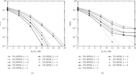
TH-BPPM,L=1 TH-BPPM,L=4 TH-BPPM,L=8 TH-BPSK,L=1 TH-BPSK,L=4
TH-BPSK,L=8 DS-BPSK,L=1 DS-BPSK,L=4 DS-BPSK,L=8
0 2 4 6 8 10 12 14 16 18 20
Eb/N0(dB)
10−5 10−4 10−3 10−2 10−1 100
BER
(a)
TH-BPPM,L=1 TH-BPPM,L=4 TH-BPPM,L=8 TH-BPSK,L=1 TH-BPSK,L=4
TH-BPSK,L=8 DS-BPSK,L=1 DS-BPSK,L=4 DS-BPSK,L=8
0 2 4 6 8 10 12 14 16 18 20
Eb/N0(dB)
10−5 10−4 10−3 10−2 10−1 100
BER
(b)
Figure8: TH- and DS-UWB-MIMO systems with variousL: (a) single user and (b) multiuser (Nu=5).
spreading sequence, the MA interference of DS systems is less than that of TH systems [14,15]. As we can see from Figure 7b, when the number of users increases, the BER of the TH-ST system increases much faster than that of the DS-ST system. Therefore, we can conclude that the DS-DS-ST system is capable of accommodating multiple users with lower BER than TH systems.
Figures8aand8bdemonstrate the effect of RAKE fin-gers to the performances of TH and DS schemes. Here, we consider UWB-ST systems with two transmit and one re-ceive antennas. The BER versus Eb/N0 curves for single-user and multisingle-user systems, each employing RAKE re-ceivers with L = 1, 4, and 8 fingers, are shown in Fig-ures 8a and 8b, respectively. The performance improve-ment with the increasing number of fingers can be ob-served from both figures. This corresponds to the fact that a RAKE receiver with more number of fingers pro-vides higher capability to capture the available signal en-ergy in dense multipath environments. Such improvement can be obviously seen in the single-user case. This sup-ports our analytical results in the previous sections that the diversity gain is increasing with L. Nevertheless, in the presence of MAI, the performance improvement of TH systems degrades rapidly, as shown in Figure 8b. On the contrary, the benefit of additional fingers is evident for DS-BPSK system in both single-user and multiuser scenarios.
In Figures9aand9b, we show the performance of single-and multiuser systems employing ROD-ST codes with full and half rates. Both figures illustrate that utilizing either
full-or reduced-rate code, BPSK provides lower BER than the BPPM scheme. FromFigure 9a, we can see that the perfor-mances of full- and half-rate ROD codes are close to each other for every modulation schemes. This is in agreement with the results (78) and (80) inSection 5, which say that for a single-user system, decreasing the rate of the ROD-ST code does not improve the performance. Unlike the single-user case, the results inFigure 9b confirm our expectation, that when the code rate is lower, both TH-BPSK and TH-BPPM multiuser systems achieve better performances, especially in high-SNR regime. However, for DS-BPSK MA systems, the BER improvement obtained from reducing the code rate is insignificant. This is because for DS multiuser system with Nu =5, the effect of MAI is considerably small, and
ROD-ST code provides close to maximum achievable performance without decreasing the code rate. Once again, DS-BPSK out-performs other modulation schemes, for both full and half rates.
7. CONCLUSIONS
TH-BPPM,Nr=1,R=1
TH-BPPM,Nr=1,R=1/2
TH-BPPM,Nr=2,R=1
TH-BPPM,Nr=2,R=1/2
TH-BPSK,Nr=1,R=1
TH-BPSK,Nr=1,R=1/2
TH-BPSK,Nr=2,R=1
TH-BPSK,Nr=2,R=1/2
DS-BPSK,Nr=1,R=1
DS-BPSK,Nr=1,R=1/2
DS-BPSK,Nr=2,R=1
DS-BPSK,Nr=2,R=1/2
0 2 4 6 8 10 12 14 16 18 20
Eb/N0(dB)
10−5 10−4 10−3 10−2 10−1 100
BER
(a)
TH-BPPM,Nr=1,R=1
TH-BPPM,Nr=1,R=1/2
TH-BPPM,Nr=2,R=1
TH-BPPM,Nr=2,R=1/2
TH-BPSK,Nr=1,R=1
TH-BPSK,Nr=1,R=1/2
TH-BPSK,Nr=2,R=1
TH-BPSK,Nr=2,R=1/2
DS-BPSK,Nr=1,R=1
DS-BPSK,Nr=1,R=1/2
DS-BPSK,Nr=2,R=1
DS-BPSK,Nr=2,R=1/2
0 2 4 6 8 10 12 14 16 18 20
Eb/N0(dB)
10−5 10−4 10−3 10−2 10−1 100
BER
(b)
Figure9: TH- and DS-UWB-MIMO systems with ROD-ST codes of different rates: (a) single user and (b) multiuser (Nu=5).
inherent in UWB environments. An example of UWB ST sig-nals based on the ROD-ST code for two-transmit-antenna systems is considered. Comparing various modulation tech-niques, we show that in the single-user case, the improve-ment of performances by using MIMO transmission is more significant in the case of TH-BPSK and DS-BPSK compared to that of TH-BPPM, whereas in MA scenarios, DS-BPSK outperform other schemes. For example, by employing two transmit and one receive antennas for a system of 5 users andEb/N0 = 8 dB, the BER for TH-BPPM decreases from 1.5×10⁻²to 9.7×10⁻³, for TH-BPSK from 10−2to 5.6×10⁻³, and for DS-BPSK from 10−2 to 4.6×10⁻³. In addition, we show that reducing the rate of the UWB-ST code would not improve the performance of single-user systems for all modulation schemes. However, in multiuser environments, reducing the code rate improves the performances of TH systems, while the improvement in the DS system is not significant.
APPENDIX
EVALUATION OFnjp,k(l)IN(17) We first expressnpj,k(l) in (17) as
njp,k(l)=
E0 Nt
Nt−1
i=0
ni jp,k(l), (A.1)
where
ni jp,k(l)
L0−1
l=0,l=l
αi j0(l)
γ
τ0(l)−τ0(l)+1−d
i
0(k) 2 Td
−γ
τ0(l)−τ0(l)+1−d
i
0(k) 2 Td−Td
. (A.2) Recall from the definition ofγ(·) in (11) thatγ[τ0(l)−τ0(l)+ (1−d0i(k))Td/2] is nonzero only for|τ0(l)−τ0(l) + (1−
di
0(k))Td/2|< Tw, that is,
τ0(l)−Tw−
1−d0i(k)
2 Td< τ0(l) < τ0(l) +Tw−
1−di
0(k) 2 Td.
(A.3) Since we assume thatTd < Twandτ0(l)−τ0(l−1)≥Tw, only
τ0(l) ∈ {τ0(l−1),τ0(l)}satisfy (A.3). Similarly,γ[τ0(l)− τ0(l) + (1−di
0(k))Td/2−Td] is nonzero for
τ0(l)−Tw−
1−di
0(k) 2 Td+Td < τ0(l)< τ0(l) +Tw−1−d
i
0(k) 2 Td+Td
and onlyτ0(l)∈ {τ0(l),τ0(l+ 1)}satisfies (A.4). Therefore After some manipulations, we have
ni jp,k(l)=αi j0(l−1)γ We assume that the relative multipath gains follow the mul-tipath intensity profile (MIP) model [26], which is defined such that the average power is one for the first path and cexp(−aτ(l))s(τ(l)) for the path with relative delay τ(l). Here,cis a log-normal random variable,ais a Gaussian ran-dom variable with mean 0.19 (/ns) and variance 0.01, and s(τ) is a log-normal process overτwith fairly constant mean of 0.638. From the MIP model, the relationship between the gains of two consecutive paths can be written as
α(l)= s
Hence, (A.7) can be reexpressed as
ni jp,k(l)=
Recall from Section 3.1 that the correlator output corre-sponding to the desired user is
ydj,k(l)= Based on the parameters in Section 6 and the correlation function in (86), we display the correlation between the two monocycles whose delay difference isdτ−Td inFigure 10. neglected without causing considerable effect to the perfor-mance evaluation.
REFERENCES
[1] Federal Communications Commission (FCC), “Revision of part 15 of the commission’s rules regarding ultra-wideband transmission systems”, First Report and Order, ET Docket 98–153, FCC 02-48, 02-48; Adopted: February 2002; Released: April 2002.
[3] M. Z. Win and R. A. Scholtz, “Energy capture vs. correlator resources in ultra-wide bandwidth indoor wireless commu-nications channels,” inProc. IEEE Military Communications Conference (MILCOM ’97), vol. 3, pp. 1277–1281, Monterey, Calif, USA, November 1997.
[4] S. M. Alamouti, “A simple transmit diversity technique for wireless communications,”IEEE J. Select. Areas Commun., vol. 16, no. 8, pp. 1451–1458, 1998.
[5] V. Tarokh, N. Seshadri, and A. R. Calderbank, “Space-time codes for high data rate wireless communication: Perfor-mance criterion and code construction,”IEEE Trans. Inform. Theory, vol. 44, no. 2, pp. 744–765, 1998.
[6] V. Tarokh, H. Jafarkhani, and A. R. Calderbank, “Space-time block codes from orthogonal designs,” IEEE Trans. Inform. Theory, vol. 45, no. 5, pp. 1456–1467, 1999.
[7] L. Yang and G. B. Giannakis, “Space-time coding for impulse radio,” inProc. IEEE Conference on Ultra Wideband Systems and Technologies (UWBST ’02), pp. 235–239, Baltimore, Md, USA, May 2002.
[8] N. A. Kumar and R. M. Buehrer, “Application of layered space-time processing to ultrawideband communication,” in Proc. 45th Midwest Symposium Circuits and Systems (MWS-CAS ’02), vol. 3, pp. 597–600, Tulsa, Okla, USA, August 2002. [9] M. Weisenhorn and W. Hirt, “Performance of binary antipo-dal signaling over indoor UWB MIMO channel,” inProc. IEEE International Conference on Communications (ICC ’03), vol. 4, pp. 2872–2878, Anchorage, Alaska, USA, May 2003.
[10] W. Siriwongpairat, M. Olfat, and K. J. R. Liu, “On the per-formance evaluation of TH and DS UWB MIMO systems,” in Proc. IEEE Wireless Communications and Networking Confer-ence (WCNC ’04), vol. 3, pp. 1800–1805, Atlanta, Ga, USA, March 2004.
[11] R. A. Scholtz, “Multiple access with time-hopping impulse modulation,” inProc. IEEE Military Communications Confer-ence (MILCOM ’93), vol. 2, pp. 447–450, Boston, Mass, USA, October 1993.
[12] M. L. Welborn, “System considerations for ultra-wideband wireless networks,” inProc. IEEE Radio and Wireless Confer-ence (RAWCON ’01), vol. 2, pp. 5–8, Waltham, Mass, USA, August 2001.
[13] J. R. Foerster, “The performance of a direct-sequence spread ultrawideband system in the presence of multipath, nar-rowband interference, and multiuser interference,” inProc. IEEE Conference on Ultra Wideband Systems and Technologies (UWBST ’02), pp. 87–91, Baltimore, Md, USA, May 2002. [14] N. Boubaker and K. B. Letaief, “Ultra wideband DSSS for
multiple access communications using antipodal signaling,” in Proc. IEEE International Conference on Communications (ICC ’03), vol. 3, pp. 2197–2201, Anchorage, Alaska, USA, May 2003.
[15] V. S. Somayazulu, “Multiple access performance in UWB sys-tems using time hopping vs. direct sequence spreading,” in Proc. IEEE Wireless Communications and Networking Confer-ence (WCNC ’02), vol. 2, pp. 522–525, Orlando, Fla, USA, March 2002.
[16] G. Durisi and S. Benedetto, “Performance evaluation and comparison of different modulation schemes for UWB mul-tiaccess systems,” inProc. IEEE International Conference on Communications (ICC ’03), vol. 3, pp. 2187–2191, Anchorage, Alaska, USA, May 2003.
[17] J. G. Proakis, Digital Communications, McGraw-Hill, New York, NY, USA, 4th edition, 2001.
[18] M. Z. Win and R. A. Scholtz, “Ultra-wide bandwidth time-hopping spread-spectrum impulse radio for wireless multiple-access communications,”IEEE Trans. Commun., vol. 48, no. 4, pp. 679–689, 2000.
[19] R. J. Cramer, M. Z. Win, and R. A. Scholtz, “Evaluation of the multipath characteristics of the impulse radio channel,” inProc. 9th IEEE International Symposium on Personal, Indoor and Mobile Radio Communications (PIMRC ’98), vol. 2, pp. 864–868, Boston, Mass, USA, September 1998.
[20] M. Z. Win and R. A. Scholtz, “Impulse radio: How it works,” IEEE Communications Letters, vol. 2, no. 2, pp. 36–38, 1998. [21] C. M. Canadeo, M. A. Temple, R. O. Baldwin, and R. A.
Raines, “Code selection for enhancing UWB multiple access communication performance using TH-PPM and DS-BPSK modulations,” inProc. IEEE Wireless Communications and Networking Conference (WCNC ’03), vol. 1, pp. 678–682, New Orleans, La, USA, March 2003.
[22] M. Nakagami, “Them-distribution: A general formula of in-tensity distribution of rapid fading,” inStatistical Methods in Radio Wave Propagation, W. G. Hoffman, Ed., pp. 3–36, Perg-amon, Oxford, UK, 1960.
[23] R. A. Horn and C. R. Johnson, Matrix Analysis, Cambridge University Press, New York, NY, USA, 1985.
[24] M. K. Simon and M. S. Alouini, Digital Communication over Fading Channels: A Unified Approach to Performance Analysis, John Wiley & Sons, New York, NY, USA, 2000.
[25] F. Ramirez-Mireles and R. A. Scholtz, “Multiple-access per-formance limits with time hopping and pulse position mod-ulation,” inProc. IEEE Military Communications Conference (MILCOM ’98), vol. 2, pp. 529–533, Boston, Mass, USA, Oc-tober 1998.
[26] S. S. Ghassemzadeh, L. J. Greenstein, T. Sveinsson, and V. Tarokh, “A multipath intensity profile model for residen-tial environments,” inProc. IEEE Wireless Communications and Networking Conference (WCNC ’03), vol. 1, pp. 150–155, New Orleans, La, USA, March 2003.
W. Pam Siriwongpairat received the B.S. degree in electrical engineering from the Chulalongkorn University, Bangkok, Thai-land, in 1999, and the M.S. degree in elec-trical engineering from the University of Maryland, College Park, in 2001. She is cur-rently a Ph.D. student in the Department of Electrical and Computer Engineering and Institute for Systems Research, the Univer-sity of Maryland, College Park. Her current
research interests include signal processing, wireless communica-tions, and networking, with particular focus on ultra-wideband communications. Her research encompasses time and space-frequency coding for multiantenna ultra-wideband systems.
Masoud Olfatreceived the B.S. degree in electrical engineering from Sharif Univer-sity of Technology, Tehran, Iran, in 1993, and the M.S. and Ph.D. degrees both in electrical engineering from the University of Maryland, College Park, in 1998 and 2003, respectively. From October 1995 to August 1996, he worked at CASE Center, Syracuse University, Syracuse, NY, as a Research As-sistant. In 1998, he joined Odyssey
while holding a Postdoctoral Research Associate appointment with the Institute for Systems Research, the University of Maryland, College Park. His current research interests include statistical sig-nal processing, coding, power control, multiple antenna schemes (including beamforming, spatial multiplexing, and space-time and frequency coding), scheduling, and QoS schemes for wireless com-munications systems, with a special interest in OFDM and UWB systems. Dr. Olfat ranked first in the Iranian universities’ nation-wide entrance examinations in the western provinces of Iran in 1984.
K. J. Ray Liureceived the B.S. degree from the National Taiwan University in 1983, and the Ph.D. degree from UCLA in 1990, both in electrical engineering. He is a Professor in the Electrical and Computer Engineering Department and Institute for Systems Re-search, the University of Maryland, College Park. His research contributions encompass broad aspects of multimedia communica-tions and signal processing; wireless