Combined Wavelet Video Coding and Error Control
for Internet Streaming and Multicast
Tianli Chu
Department of Electrical Engineering, Texas A&M University, College Station, TX 77843, USA Email:[email protected]
Zixiang Xiong
Department of Electrical Engineering, Texas A&M University, College Station, TX 77843, USA Email:[email protected]
Received 23 December 2001 and in revised form 9 September 2002
This paper proposes an integrated approach to Internet video streaming and multicast (e.g., receiver-driven layered multicast (RLM) by McCanne) based on combined wavelet video coding and error control. We design a packetized wavelet video (PWV) coder to facilitate its integration with error control. The PWV coder produces packetized layered bitstreams that are independent among layers while being embedded within each layer. Thus, a lost packet only renders the following packets in the same layer useless. Based on the PWV coder, we search for a multilayered error-control strategy that optimally trades offsource and channel coding for each layer under a given transmission rate to mitigate the effects of packet loss. While both the PWV coder and the error-control strategy are new—the former incorporates embedded wavelet video coding and packetization and the latter extends the single-layered approach for RLM by Chou et al.—the main distinction of this paper lies in the seamless integration of the two parts. Theoretical analysis shows a gain of up to 1 dB on a channel with 20% packet loss using our combined approach over separate designs of the source coder and the error-control mechanism. This is also substantiated by our simulations with a gain of up to 0.6 dB. In addition, our simulations show a gain of up to 2.2 dB over previous results reported by Chou et al.
Keywords and phrases:wavelet video coding, error control, internet streaming, multicast, PWV.
1. INTRODUCTION
In recent years, we have witnessed explosive growth of the In-ternet. Driven by the rapid increase of bandwidth and com-puting power and, more importantly, the consumer’s insa-tiable demand for multimedia content, media streaming over the Internet has quickly evolved from novelty to mainstream in multimedia communications. As the flagship applica-tion that underscores the ongoing Internet revoluapplica-tion, video streaming has become an important way for information distribution. For example, distance learning, telemedicine, and live webcast of music concerts and sports events are all benefiting from video streaming technology. People are al-ready more and more dependent on this new technology in their daily lives and business. As such, Internet video stream-ing has attracted attention from both the industry (e.g.,
Mi-crosoft and RealNetworks) and academia [1,2,3].
From a schematic point of view, Internet video stream-ing involves video compression, Quality-of-Service (QoS) control (error control and congestion control), streaming servers, streaming protocols, and media synchronization, of which the first two components are the most important.
Compression is a must in video streaming, because full motion video requires at least 8 Mbps bandwidth. A com-pression ratio of over 200 : 1 is needed for the transmis-sion of video over a 56 kbps modem connection! Inter-national standards like MPEG-4 [4] and H.263+ [5] for video compression have been developed during the past five years for the applications related to streaming me-dia. Nowadays, commercial client players (e.g., QuickTime, Windows Media Player and RealOnePlayer) employ mostly MPEG-4 or H.263+ related technologies. In the mean-while, corporate companies are developing new scalable video-coding technology over and beyond the MPEG-4 and H.263+ standards. For example, Microsoft chose the 3D SPIHT coder [6] as a core technology in its next-generation video streaming product. A key feature of the 3D SPIHT coder is that it is 100% scalable—there is no
performance penalty due to scalability. This is different
from MPEG-4 fine-granularity scalable (FGS) coding [7],
which suffers a loss of 1–1.5 dB compared to single-layer
MPEG-4 coding. Details on source coding—3D embedded
wavelet video coding in particular—are provided inSection
Another reason for our emphasis on 3D embedded wavelet video coding is that today’s streaming video appli-cations mostly use unicast. There is an increasing momen-tum to move towards multicast applications [8] and bring the broadcasting flavor [9] to the streaming world. Because layered source coding can be conveniently used to deal with bandwidth heterogeneity in the Internet, it is the foundation of receiver-driven layered multicast (RLM) [10], in which the
sender broadcasts source and parity packets to different
mul-ticast groups after layered source coding and channel coding. Each receiver estimates its available bandwidth and accord-ingly subscribes to the right combination of multicast groups to optimize its video quality.
Since the Internet is the best-effort network that offers
no QoS guarantee, ambient packet loss is inevitable in the Internet and the use of error-control techniques is thus nec-essary. The purpose of error control is to use the avail-able transmission rate, as determined by the
congestion-control mechanism [11,12], to mitigate the effects of packet
loss. Error control is generally accomplished by transmit-ting some amount of redundant information to compensate for the loss of some important packet. This is achieved via
joint source-channel coding (JSCC) [13,14,15] by finding
the optimal source-redundancy mix or source-channel
cod-ing trade-off. Internet video streaming requires that
pack-ets be received within a bounded delay. Therefore, error-control techniques, such as forward error correction (FEC), are often used. Unequal error protection (UEP) using rate-compatible codes was popularized by Hagenauer [16]. It can
be achieved by fixing the source block length K and
vary-ing the channel block length N across the different source
layers.
Chou et al. [17] addressed error control for RLM based on the 3D SPIHT coder [6] that encodes each group of frames (GOF) of a video sequence into an embedded bit-stream. Each 3D SPIHT bitstream is uniformly divided into a series of 1000-byte source packets; parity packets are gen-erated with Reed-Solomon (RS) style erasure codes; an iter-ative descent algorithm is used to compute the JSCC solu-tion in the form of UEP for the given bandwidth and packet loss probability. Each receiver first estimates the channel con-dition and then follows this solution to join the multicast groups for optimal collection of source and parity packets.
While the error-control mechanism in [17] can be ap-plied to any layered source bitstream, no interaction exists between source coding and error control. This separate de-sign philosophy has some drawbacks. To see this, we note that 3D SPIHT packets are sequentially dependent, and
los-ing any packet will render all the followlos-ing packets in the
en-tirebitstream useless, even though these packets are correctly
received.
In this paper, we take an integrated approach [18,19]
to-ward joint source coding and error control by incorporat-ing packetization and layered codincorporat-ing in the source coder and finding a new error-control strategy. Our approach applies equally to unicast and multicast. In the sequel, we base our exposition on multicast in general and RLM in particular as unicast is a special case of multicast.
We design a packetized wavelet video (PWV) coder based on the work in [20] that generates layered bitstreams that are independent among layers while being embedded within each layer. Packetization is simply done by rounding each layer of the bitstream to its nearest packet boundary. This was
shown to suffer little source-coding performance loss in [21].
The PWV coder achieves better rate-distortion (R-D)
per-formance than 3D SPIHT. In addition, and because different
layers in the PWV bitstream are independent, a lost packet in the PWV bitstream only renders the following packets in the
same layer useless. It will not affect packets in other layers,
making it more error-robust than 3D SPIHT.
Layered channel coding is accomplished in our system using a systematic rate-compatible RS style erasure code [22]. The server multicasts all PWV bitstream layers and all par-ity layers to separate multicast groups. With error control, each receiver can decide to subscribe to or unsubscribe from the multicast groups based on the packet loss ratio and the available channel bandwidth, as determined by the
conges-tion control mechanism [11,12].
The layered structure of PWV calls for error-control
strategies in video streaming that offer UEP not only among
bitstream layers, but also within packets in each layer. It is this interplay between source coding and error control that distinguishes our integrated paradigm from past “plug-and-use” approaches. We formulate a rate-allocation problem
and give amulti-layered error control solution in the form
of optimal collection of multicast groups (or collection of source and channel layers) for the receiver to subscribe. This FEC-based error-control mechanism can be constructed as an extension of the approach in [17], which is single-layered in nature.
Using ideas of the “digital fountain” approach [23], we
also consider pseudo-ARQ [17, 24] in the above FEC
sys-tem for reliable multicast by sending delayed parity packets to some additional multicast groups at the server. Within a tolerable delay bound, the receiver is allowed to join and sub-sequently leave these groups to retrieve packets that are lost in previous transmissions. Error control in this FEC/pseudo-ARQ system in terms of a receiver joining and leaving mul-ticast groups is given by the subscription policy in a finite-horizon Markov decision process [15].
While both the PWV coder and the multilayered error-control strategy are new—the former incorporates embed-ded wavelet video coding and packetization and the latter extends the single-layered approach in [17]—the main con-tribution of this paper lies in the synergistic integration of the two. Theoretical analysis shows a gain of up to one dB on a channel with 20% packet loss using our combined ap-proach over separate designs of the source coder and the error-control mechanism. This is also substantiated by our simulations with a gain of up to 0.6 dB.
Recent work [24,25,26] on multimedia streaming has
Receiver
Control process RS
decoder PWV
decoder
PWV packets
PWV packets
Parity packets
Subscribed packets Subscription
messages Network
Receiver Receiver Playback
Recovered video Video storage
Raw sequences Video cam.
Raw sequences
PWV encoder
RS encoder PWV
packets
PWV packets
Parity
packets Server
Multicast
Figure1: Block diagram of our integrated video multicast system.
(see Figure 1for the block diagram of our system). We do
not address congestion control [11, 12] in this work,
al-though our system allows easy incorporation of TCP-friendly congestion-control protocols to form a true end-to-end ar-chitecture for video streaming. This opens doors for more exciting research and we leave this aspect of our work to fu-ture publications.
The rest of this paper is organized as follows.Section 2
focuses on our source-coding and packetization schemes
that lead to the PWV coder. Section 3describes our
FEC-based error-control model, while Section 4 presents
com-bined PWV coding and FEC-based error control.Section 5
considers pseudo-ARQ and outlines the pseudo-ARQ-based
error-control model.Section 6presents combined PWV
cod-ing and FEC/pseudo-ARQ.Section 7includes both analytical
and simulation results.Section 8concludes the paper.
2. SOURCE CODING AND PACKETIZATION
In this section, we describe our schemes for source coding and packetization, leading to the development of a PWV coder that facilitates easy integration with error control for Internet streaming.
2.1. Source coding
Although international standards like MPEG-2 [27] for video compression have been developed during the past decade for a number of important commercial applications
(e.g., satellite TV and DVD), these algorithms cannot meet the general needs of Internet video because they are not de-signed or optimized for handling packet loss and heterogene-ity in the emerging world of packet networks. Scalable cod-ing, also known as layered, embedded, or progressive codcod-ing, is very desirable in Internet streaming because it encodes a video source in layers, like an onion, that facilitate easy
band-width adaptation. But it is extremely difficult to write a
com-pression algorithm that can layer the data properly, without a performance penalty. That is, a scalable compression al-gorithm inherently delivers lower quality than an alal-gorithm that can optimally encode the source monolithically, like a
solid ball. So, the difficulty lies in minimizing the effect of
this structural constraint on the efficiency of the
compres-sion algorithm, both in terms of computational complexity and quality delivered at a given bandwidth.
3D wavelet video coding [31,32,33,34] deviates from the standard motion compensated DCT approach in H.263+ or MPEG-4. Instead, it seeks after alternative means of video coding by exploiting spatiotemporal redundancies via 3D wavelet transformation. Promising results have been re-ported. For example, Choi and Woods [34] presented better results than MPEG-1 using a 3D subband approach, together with hierarchical variable-size block-based motion compen-sation. In particular, the 3D SPIHT [6] video coder, which is a 3D extension of the celebrated SPIHT image coder [35], was chosen by Microsoft as the basis of its next-generation streaming video technology [17]. The latest 3D embedded wavelet video (3D EWV) coder [20], which borrows ideas from the 2D EBCOT algorithm [36], showed for the first time that 3D wavelet video coding outperforms MPEG-4 coding by as much as 2 dB for most low-motion and average-motion sequences. 3D EWV also has comparable performance to MPEG-4 for most high-motion sequences. In this work, we choose to use the 3D EWV coder because of its good per-formance and its embeddedness. In the following, we briefly review the 3D EWV coding algorithm.
The Daubechies 9/7 biorthogonal filters of [37] are used in all three dimensions to perform a separable wavelet de-composition in the 3D EWV coder. The temporal trans-form and 2D spatial transtrans-form are done separately by first performing a dyadic wavelet decomposition in the tempo-ral direction, and then within each of the resulting tempotempo-ral bands, performing three levels of a 2D spatial dyadic decom-position.
After 3D wavelet transformation, the wavelet coefficients
can be coded with a bit-plane coding scheme like 3D SPIHT [6]. The 3D EWV algorithm is more powerful yet flexible than 3D SPIHT. It is powerful because the context forma-tion in arithmetic coding does not have to be restricted to the rigid cubic structure imposed by zerotrees in 3D SPIHT. It is flexible due to the fact that samples on each bit-plane are coded one at a time, making the extension to object-based coding very easy. The core of the algorithm consists of the following three parts.
(1) 3D context modeling. Adaptive context formation in 3D EWV primarily relies on a binary-valued state variableσ[i, j, k] that characterizes the significance1of coefficient x[i, j, k] at position [i, j, k] after subband transposition. It is initialized to 0 and toggled to 1
when x[i, j, k]’s first nonzero bit-plane value is
en-coded. Depending on the state ofσ[i, j, k], the binary information bit ofx[i, j, k] is coded at each bit-plane using one of the following three primitives: zero cod-ing (ZC), sign codcod-ing (SC), and magnitude refinement (MR). Ifσ[i, j, k]=0 in the current bit-plane, ZC and
SC are used to code new information aboutx[i, j, k];
otherwise, MR is used instead. Each of the above three coding primitives has its own context formation and assignment rules.
1A coefficient is called significant if it is nonzero at the current bit-plane
level.
Figure2: Immediate neighbors are considered in context formation and assignments for ZC in 3D EWV.
(i) ZC. When a coefficientx[i, j, k] is not yet signifi-cant in previous bit-planes, this primitive is used to code new information about whether it be-comes significant or not in the current bit-plane. ZC uses significance information aboutx[i, j, k]’s immediate neighbors as contexts to code its own
significance information (seeFigure 2).
(ii) SC. Oncex[i, j, k] becomes significant in the cur-rent bit-plane, the SC primitive is called to code its sign. SC also utilizes high-order context-based arithmetic coding with fourteen contexts. (iii) MR. This primitive is used to code new
infor-mation aboutx[i, j, k] if it becomes significant in a previous bit-plane. MR uses three contexts for arithmetic coding.
(2) Fractional bit-plane coding. With the above three cod-ing primitives in plane codcod-ing, an embedded bit-stream can be generated for each subband with excel-lent coding performance. The practical coding gain of 3D EWV over 3D SPIHT [6] (and EBCOT [36] over SPIHT [35]) stems from two aspects: one lies in high-order context modeling for SC and MR; the other one is the use offractional bit-plane coding, which provides
a practical means of scanning the wavelet coefficients
within each bit-plane for R-D optimization at different
rates. Specifically, the coding procedure in 3D EWV consists of three consecutive passes in each bit-plane.
(i) Significance propagation pass. This pass pro-cesses coefficients that are not yet significant but
have a preferred neighborhood. A coefficient is
designated as having a preferred neighborhood if and only if it has at least one significant im-mediate diagonal neighbor for diagonal bands, or at least one significant horizontal, vertical, or temporal neighbor for other bands. For these
co-efficients, the ZC primitive is used to code their
significance information in the current bit-plane and, if any of them becomes significant in the current bit-plane, the SC primitive is used to compress their sign bits.
(ii) Magnitude refinement pass. Coefficients that
in this pass. The binary bits corresponding to
these coefficients in the current bit-plane are
coded by the MR primitive.
(iii) Normalization pass. Processed in this pass are
co-efficients that were not coded in the previous two
passes. These coefficients are not yet significant,
so only ZC and SC are applied in this pass. Each of the above passes processes one fractional bit-plane in the natural raster scan order. Note that
pro-cessing ZC and MR in different fractional bit-planes
comes naturally from their separate treatments in con-text modeling. In addition, the processing order of the three fractional bit-planes follows the order of their perceived R-D significance levels. The first fractional bit-plane typically achieves a higher R-D ratio than the second one, which in turn is easier to code than the third one. Using fractional bit-plane coding thus en-sures that each subband gives an R-D optimized em-bedded bitstream.
(3) Bitstream construction and scalability. In the previous coding stage of 3D EWV, an embedded bitstream is generated for each subband. In this stage, bitstreams
corresponding to different subbands are truncated and
multiplexed to construct a final bitstream. The ques-tion now is how to determine where to truncate a
bit-stream and how to multiplex different bitstreams in
order to provide functionalities such as rate and res-olution scalability. The bitstream truncation and mul-tiplexing procedure is described as follows.
(i) Bitstream truncation with R-D optimization. Given a target bit rateR0, our objective is to con-struct a final bitstream that satisfies the bit rate constraint and meanwhile minimizes the overall distortion. The end of each fractional bit-plane is a candidate truncation point. The R-D pair at each candidate truncation point can be obtained by calculating the bitstream length and distor-tion at that point. An operadistor-tional R-D curve can be constructed for each subband. All valid trun-cation points must lie on the convex hull of the R-D curve to guarantee R-D optimality at each truncation point. Optimal rate allocation over all subbands is achieved when operation points on
all operational R-D curves have an equal slopeλ.
The slopeλ0, corresponding toR0, is found via a fast bisectional algorithm [38].
(ii) Multilayer bitstream construction. To make anL
-layer bitstream,LR-D slopesλ1, λ2, . . . , λL with |λ1| > |λ2| > · · · > |λL| are first chosen. A
corresponding truncation point (hence a layer of bitstream) is found from each subband for every
R-D slopeλi. The corresponding layers from all
the subbands constitute theith layer of the final
bitstream. Depending on its available bandwidth and computational capability, the receiver can se-lectively decode the first few layers.
(iii) Bitstream scalability. Fractional bit-plane cod-ing in 3D EWV ensures that the final bitstream
is scalable with fine granularity. Furthermore, the final bitstream can be rearranged to achieve other functionalities easily because the offset and length of each layer of bitstream for each sub-band are coded in the header of the bitstream. This makes the final bitstream very flexible for use in applications like video browsing and mul-ticasting over the Internet.
2.2. Packetization
In the above original EWV coder, bitstream truncation at the end of each fractional bit-plane (i.e., treating each fractional bit-plane as a basic unit in bitstream formation) makes sense because each bit spent in coding a fractional bit-plane re-duces the distortion by roughly the same amount. In
addi-tion, multiplexing different layers according to the
decreas-ing magnitudes of their R-D slopes gives the best progressive coding performance. These strategies work great in terms of improving source-coding performance. But they might not be suitable for designing source coders for video streaming applications that involve JSCC, in which it often pays to leave some redundancy in the source bitstream. Thus, our phi-losophy in packetization is to achieve bitstream resynchro-nization and easy integration with error control via judicious modification of the original EWV coder so that the sacrifice in source-coding performance is small.
Note that packetizing the original EWV bitstream into fixed-length packets, in general, is not allowed, because the truncation points in the EWV bitstream typically are not set on packet boundaries. This is due to the fact that the EWV bitstream is not as fine-grained as the 3D SPIHT bitstream,
which can be truncated at thebytelevel, making fixed-length
packetization trivial as in [17].
To rectify this shortcoming in the original EWV bit-stream, we mark any multiple of packet size in the bitstream (instead of the end of each fractional bit-plane) as a candi-date truncation point in EWV coding. In addition, we skip
the bitstream multiplexing step and outputmultiplelayered
bitstreams in the new video coder for the purpose of in-creasing error resilience. In forming each bitstream layer, we note that the original 3D EWV coder already provides lots of flexibilities—it allows a multilayered structure with each layer corresponding to one or several subbands and also achieves spatial/temporal scalability by coding each group of subbands independently into an embedded bitstream. In this work, we form layers by resolution, that is, we choose to en-code all the subbands in each resolution into an embedded
bitstream for each layer. SeeFigure 3for a 2D example.
The bitstream layers allow R-D truncation at each layer for a given target bit rate (typically given in terms of the num-ber of packets per GOF). Because of the constraint that can-didate truncation points for each bitstream layer must lie on packet boundaries, optimal rate allocation over all layers is achieved when the slopes at operation points on all
opera-tional R-D curves areapproximatelyequal.
Layer 4 Layer 3 Layer 2 Layer 1
Figure3: A 2D example where all the subbands in each resolution are coded into an embedded bitstream for each layer.
Layer 4 Layer 3 Layer 2 Layer 1
GOF 1 GOF 2 GOFK
· · ·
Figure4: The PWV coder generates packetized layered bitstreams for each GOF that are independent among layers while being em-bedded within each layer.
packets and being embedded (seeFigure 4). We call it a 3D
PWV coder. For example, when a color QCIF sequence is coded at 50 packets (1000 bytes per packet) per GOF of 32 frames using a three-level wavelet transform, the lengths of the four bitstream layers are typically 2, 6, 17, and 25 pack-ets. Each layer of the PWV bitstream can be independently decoded, thus error resilience is improved during transmis-sion when compared with transmitting the original EWV bit-stream.
It was shown in [21] that the source coding performance of the PWV coder is very close to that of the original EWV coder. That is, the performance loss due to packetization is very small when there is no packet loss. To see this, the PWV
Layer 4 Layer 3 Layer 2 Layer 1
GOF 1 GOF 2 GOFK 1 2 3 Nmax−K
· · · ·
Parity packets Source packets
Figure5: The (Nmax, K) rate-compatible RS erasure code is used to
generateNmax−Kparity packets for eachK-packet coding block.
A typical receiver subscribes to source/parity packets highlighted in shaded areas.
bitstream can be thought of as a slightly modified version of the original EWV bitstream after rounding each EWV bit-stream layer to its nearest packet boundary by either pruning the extra fractional packet or growing it out to fill the re-maining fractional packet. Of course, the EWV bitstream
for-mation involves multiplexing or interleaving of different
bit-stream layers whereas there is no such a step in PWV coding. In summary, the PWV coder achieves a performance close to EWV with very low complexity using a simple packetization scheme.
3. FEC-BASED ERROR-CONTROL MODEL
We now discuss our FEC-based error-control model. As we
can see from Figure 4, the PWV bitstream in each layer is
divided and packetized into a certain number of packets;
packets from different GOFs along the horizontal (or time)
axis form a sublayer. We partition each sublayer into coding
blocks, each havingKsource packets. The blocksizeKis
con-stant across all sublayers. For each coding block, we apply a systematic (Nmax, K) RS style erasure correction code [22] to
produceNmax−Kparity packets (seeFigure 5). AndNmax−K
is the maximum amount of redundancy that will be needed by the transmitter to protect the source layer. It is determined
by the worst channel condition. TheNmax−Kparity
pack-etsp1, . . . ,pNmax−Kare generated byte-wise from theKsource
packetss1, . . . ,sKin the coding block by
s1· · ·sK|p1· · ·pNmax−K
=s1· · ·sKG, (1)
where
G=IK|PK,Nmax−K
(2)
is the generator matrix over the finite Galois field GF(28) that
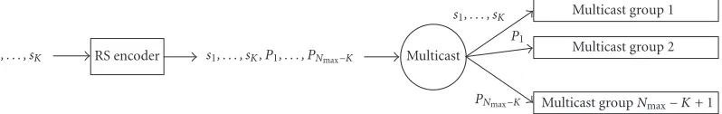
Multicast groupNmax−K+ 1
Figure6: A coding block in any sublayer is first encoded to generateNmax−Kparity packets, then the resultingNmaxsource plus parity
packets are sent toNmax−K+ 1 multicast groups.
parity generation matrix. The erasure code possesses the
property that a minimum ofK source/parity packets suffice
to recover theKsource packets.
In our RLM system with FEC, the transmitter buffers
frames as they arrive. When a GOF is accumulated, it gen-erates a PWV bitstream for this GOF. After PWV bitstreams
are generated for K GOFs, the transmitter computes the
Nmax−K parity packets for each coding block ofK source
packets. TheKsource packets are broadcasted to one
multi-cast group, while theNmax−Kparity packets are broadcasting
toNmax−Kmulticast groups. This is illustrated inFigure 6.
Thus, a coding block usesNmax−K+ 1 multicast groups in
total. Note that this scheme, also used in [17,39], is different from traditional FEC schemes [40] that broadcast all par-ity packets to one multicast group. It avoids overwhelming the network with unduly heavy load from unwanted parity packets.
According to the current network condition (e.g., packet loss ratio and available bandwidth), for each coding block a receiver makes its own decision in terms of which mul-ticast groups of that block to subscribe. The receiver can subscribe to no multicast group at all, to the first multicast group only at low latency, or to the first multicast group plus any number of multicast groups for improved video qual-ity but at high latency. This allows the receiver to trade la-tency for quality—another advantage of the multicast
struc-ture ofFigure 6. Source/parity packets in the shaded areas in
Figure 5indicate those the receiver subscribes to in different coding blocks. Note that unsubscribed packets typically re-side at the bottom of each bitstream layer as they are less im-portant in the R-D sense. This corresponds to UEP strategies not only among PWV bitstream layers, but also among
pack-ets within each layer—a scenario that is markedly different
from the case considered in [17].
From the received source/parity packets, the receiver in-stantly recovers as many source packets as possible and de-code them. As long as the total number of correctly received
packets in an RS coded block is greater than or equal toK,
all the K source packets can be recovered. Playback begins
afterKGOFs are decoded. Thus the delay is the duration of
KGOFs.
Due to the fact that the tolerable coding delay is limited
for streaming video, the lengthKin a channel-coding block
should be small. For example,K =8 corresponds to a
cod-ing delay of roughly eight seconds if the GOF size is 32. For
such a small value ofK, the RS erasure code is a good choice
because of its maximal erasure correction capability [22] and low complexity.
4. COMBINED PWV CODING AND FEC-BASED ERROR CONTROL
In this Section, we assume that a congestion-control mecha-nism (e.g., AIMD [11] and TCP-friendly RAP [12]) is avail-able and formulate the multilayered error-control problem under a fixed transmission rate and packet loss ratio.
4.1. Problem formulation
To facilitate easy intergration of PWV coding and FEC-based
error control, PWV bitstreams for different GOFs are
gener-ated so that the number of layers and the number of pack-ets/sublayers within each layer are fixed. Suppose that the
PWV bitstream for each GOF has Llayers with Pl packets
in thelth layer. Assume that the receiver subscribes to a total
ofNl,isource plus parity packets per coding block in sublayer
{l, i}(which is theith sublayer of thelth layer). These packets
are highlighted in the shaded areas inFigure 5.
Define N = (N1,1, . . . , N1,P1, . . . , NL,1, . . . , NL,PL) as the rate allocation vector. It specifies the rate allocation between source packets and parity packets within each source sub-layer. The total transmission rate, in terms of packets per GOF, is given by
R(N)=
Nl,i > K, the factorNl,i/K measures the redundancy which
the receiver chooses in order to protect source packets in sub-layer{l, i}. If the packet losses are independent with
proba-bility, then, after channel decoding, any packet in that
sub-layer can be recovered with probability
The double sum computes the expected number of correctly recovered source packets within one coding block in sublayer
{l, i}. Note that whens+c≥K, all theKsource packets can be recovered. While ifs+c < K, this number can only bes, no matter how many parity packets are received. The expected reconstruction distortion per GOF is given by
D(N)=D0−
D0is the expected reconstruction distortion when the
trans-mission rate is zero, and∆Dl,irepresents the expected
reduc-tion of distorreduc-tion if the packet in sublayer{l, i}can be
de-coded. LetDl,0 be the expected reconstruction distortion of
thelth layer when the transmission rate is zero, then we have
D0=
L l=1Dl,0.
In our analysis, we use an operational distortion-rate
function D(R) = σ22−2R/A to model the R-D performance
of the PWV coder, where A is a scaling factor. Based on
this model, ∆Dl,i can be computed from Dl,0 as ∆Dl,i =
Dl,0(2−2i/Al−2−2(i−1)/Al). Because each layer of the PWV bit-stream is embedded, a packet is dependent on those ahead of
it within the same layer. That theith packet can be decoded
implies that thei−1 packets ahead of it can also be correctly
decoded; this dependency is reflected in (6).
Equations (3) and (5) give the total transmission rate and the expected distortion as a function of the rate allocation
vectorN. Now we want to find the optimal rate allocation
vector to minimize the expected distortion subject to a trans-mission rate constraint. That is, we consider the following constraint optimization problem:
min
N D(N) subject toR(N)≤R0, (7)
whereR0is the given rate constraint.
4.2. The optimization algorithm
One way to solve the above problem is by finding the rate
allocation vectorNthat minimizes the Lagrangian
J(N)=D(N) +λR(N)
The solution to this problem is completely
character-ized by the set of distortion increments∆Dl,i, which are
de-termined by the source coding and packetization, and the
probabilityPl,i(Nl,i) with which a packet in sublayer{l, i} can be correctly recovered, which is in turn determined by the channel coding. There are many methods to solve this
optimization problem with a rate constraint [13,14,15].
We solve this problem by using an iterative approach that is based on the method of alternating variables for multivari-able minimization [41]. The objective function
J(N)=JN1,1, . . . , N1,P1, . . . , NL,1, . . . , NL,PL
(9)
in (8) is minimized over one variable at a time, while keeping the other variables constant, until convergence. To be spe-cific, letN(0)be the initial rate allocation vector. LetN(t) =
(N1(t,1), . . . , NL,P(t)L) be determined fort = 1,2, . . . ,as follows.
Select one component Nlt,it ∈ {N1,1, . . . , NL,PL}to optimize
at stept. This can be done in a round-robin style. Then for
Nl,i(l=ltori=it), letNl,i(t)=N(t−1)
l,i . ForNlt,it, we perform the following rate optimization:
N(t)
Equation (11) contains only those items in (8) that are re-lated to Nlt,it. For fixedλ, the 1-dimensional minimization problem (11) can be solved using standard nonlinear op-timization procedures, such as gradient-descent-type
algo-rithm [41]. Now, in order to minimize the LagrangianJ(N)
given by (8), we proceed as follows: first, for fixedλ, we min-imizeJ(N, λ) and get a total transmission rateR(N, λ). Com-pare this rate with the target transmission rate and
accord-ingly adjustλ. This procedure is repeated until convergence.
Generally, the resultingR(N) will not be exactly equal to the target rate constraint, because it only picks limited discrete values.
In our experiments, we always start with the initial rate allocation vectorN =(1,1, . . . ,1). We cycle through all the components, beginning with the component associated with the first sublayer and ending with the component associated with the last sublayer. The resulting rate allocation
N∗=N1∗,1, . . . , N1∗,P1, . . . , N
∗
L,1, . . . , NL,P∗L
(12)
gives the optimal error-control solution, generally in the
form of unequal error protection, for the different source
sublayers.
5. PSEUDO-ARQ-BASED ERROR-CONTROL MODEL
feedback implosion problem. As a common approach, feed-back suppression partially solves this problem at the expense of increased latency, more complexity at receivers, or addi-tional requirements of the network.
Nonnenmacher et al. [40] demonstrate that hybrid FEC/ARQ is very powerful in reducing the number of re-transmissions at low packet loss rate. But it cannot com-pletely eliminate the need of retransmissions, especially when the number of receivers grows large or the packet loss rate becomes high. Byers et al. [23] further develop this idea by
using pure FEC to form adigital fountainfor reliable
multi-cast of bulk data. It can be viewed as a form of pseudo-ARQ. Application of hybrid FEC/Pseudo-ARQ to video multicast
is studied in [17,24]. ARQ is simulated by sending delayed
parity packets to some additional multicast groups. The ceiver can join and subsequently leave these groups to re-trieve packets that are lost in previous transmissions. This scheme can satisfy the retransmission needs of a large num-ber of receivers with a small numnum-ber of retransmitted parity packets.
In our work, we also applied this hybrid method on the PWV encoded video for multicast. Specifically, instead of being transmitted at the same time of the source pack-ets, some of the parity packets are multicast in subsequent
time slots with different delays. According to the current
number of received packets, the network condition, and the available transmission rate, each receiver can choose to join these multicast groups to retrieve the delayed parity pack-ets.Figure 7depicts the flowgraph of our pseudo-ARQ-based error-control scheme. Obviously, this pseudo-ARQ scheme
is more efficient than pure FEC because the delayed parity
packets are subscribed to only when necessary. However, this
efficiency is at the expense of larger latency. In real
applica-tions, the tolerable latency is limited and the number of deci-sion time slots should also be fixed. Thus we have a problem
of making optimal subscription decisions at different time
slots in order to minimize the expected reconstruction dis-tortion under a transmission rate constraint.
6. COMBINED PWV CODING AND FEC/PSEUDO-ARQ
Just as in pure FEC, the goal of error control in hybrid FEC/pseudo-ARQ is to minimize the expected distortion in the reconstruction given a transmission rate constraint. However, with ARQ the receiver can take a series of actions based on the state of each step. This control process at each receiver can be modeled as a finite horizon Markov decision process [15]. A Markov decision process with finite horizon
W is aW-step stochastic process through a state space. An
action is associated with each trellis state to maximize or minimize an expected quantity. The assignment of actions to trellis states is called a policy.
In this problem, each statesin the trellis space is uniquely
determined by the number of received source packetsx, the
number of total received packetsk, and the step number (or
time index) w. We want the policyπ to minimizeJ(π) =
D(π) +λR(π). This can be solved by a dynamic
program-ming algorithm, which regressively minimizes the partial
End
Figure 7: The decision process at each receiver for any sublayer. T max is the number of decision time slots.
Lagrangian J(π, s) of each statesas a function of the tran-sition probability to the next states
LetLtotal=
lPlrepresent the total number of sublayers;
letW be the number of decision steps andKthe size of an
RS coding block. The algorithm runs as follows.
Algorithm 1. (1) Initialize the policy componentsπ(l, s)of
all the layers0≤l < Ltotaland all the statess(0≤w <
W,0≤k ≤K,0≤x≤k)throughout the trellis space; setλto an initial value.
(2) Setπold(l, s)=π(l, s)for alllands. (3) Start from the first layerl=0.
(4) Start from the last stepw=W−1; setJnext(l, s)=0for
alllands.
(5) For each states, computeJ(l, s)which represents the cost
D+λRof the current layerlstarting from the current stepw, given the current policyπ andJnext(l, s)which
represents the cost starting from the next stepw+ 1.
(6) Find the optimal policy componentπ∗(l, s) (15)for all
(10) Compute the expected transmission rateRwith the cur-rent policyπ.
(11) Check if the computedRhas most closely approached the rate constraintRtarget. If not, adjustλand go to step(2).
(12) End.
7. RESULTS
7.1. Analysis
The optimization algorithm described inSection 4.2extends
the single-layered optimization algorithm in [17]. To
com-pare the performance difference between the two
error-control mechanisms, we assume that bitstreams generated by 3D SPIHT and PWV coding have the same R-D curve, that is, D(R)=σ22−2R/A. Note that the 3D SPIHT bitstream has a
se-quential dependency among all the source packets of a GOF, whereas in the PWV coder only packets within the same layer are sequentially dependent.
Applying the algorithm described in Sections4and6, we
compute the signal-to-reconstruction noise ratio as a
func-tion of the transmission rate as shown inFigure 8for =
20% and inFigure 9for=5%. We assume that the PWV
bitstream consists of four layers, with the numbers of packets in different layers being 2, 6, 17, and 25.
When only pure FEC is used, we see that integrat-ing PWV codintegrat-ing and error control outperforms the sintegrat-ingle-
single-layered approach in [17] by up to one dB when = 20%
and up to 0.6 dB when=5%. In the hybrid
FEC/pseudo-ARQ case, however, the difference of performance between
the two coders becomes very small. Note that when ARQ is introduced, any subscribed packet can almost always reach the receiver with little increase in the expected transmission
40
Packet transmission rate (packets per GOF) 0
Reconstruction of 2 idealized sources with 20% packet loss rate
1
Figure8: Analytical results using optimal error control for trans-mitting a single-layered video bitstream and a multilayered video bitstream over a network with 20% packet loss.
rate. Thus, the dependency among layers does not play a
sig-nificant role any more. Take (W, K)=(8,1), for example, if
we fix the policy componentπ(s=0, c=0, w=0)=1 and
increase the policy componentsπ(s=0, c=0,0< w <8) from 0 to 1, the expected transmission rate is increased by only 0.25 (from 1 to 1.25) packets per GOF. However, now the probability that any packet in the corresponding layer
cannot be recovered is reduced from 20% to 3×10⁻⁶. Also
note that inFigure 9for=5%, because the packet loss rate
is small enough, both (W, K) = (8,1) and (W, K) =(4,2)
can achieve near-perfect transmission. Therefore, they actu-ally share the same performance curve.
7.2. Simulations
Simulations are also carried out, in which two 288-frame
25 fps QCIF color sequences Foremanand Akiyo, encoded
using the PWV coder and protected with a systematic RS
erasure code with a block sizeK = 8, are transmitted over
a simulated network with 20% and 5% packet loss, respec-tively. Each video sequence is blocked into 9 GOFs contain-ing 32 frames per GOF and encoded at 50 packets per GOF with 1000 bytes per packet. The duration of each GOF is 1.28
seconds. Thus, the number of packets N allowed for each
GOF in term of the transmission rate Rin bps is given by
N=1.28R/8000 packets per GOF.
The quantities∆Dl,ineeded for the solution inSection 4
40
Packet transmission rate (packets per GOF) 0
Reconstruction of 2 idealized sources with 5% packet loss rate
1
Figure9: Analytical results using optimal error control for trans-mitting a single-layered video bitstream and a multilayered video bitstream over a network with 5% packet loss.
server as a side information or estimated adaptively by the receiver using previously recovered packets. For each trans-mission rate, the selected combination of source and parity packets is transmitted and each simulation runs 100 times.
In order to compare our multilayered scheme with the single-layered scheme in [17] on a fair basis, we modify the PWV coder to make it produce single-layered bitstreams. That is, the packets of each GOF have a sequential depen-dency as in 3D SPIHT. Loss of any packet will render the following packets of the same GOF useless. Thus we have a single-layered version of the PWV coder with comparable
coding efficiency to the original PWV coder. The same
pro-cedure as in [17] is applied to provide error protection for the
bitstreams generated by this new coder. In Figures10,11,12,
and13, we refer to the single-layered PWV coder as sPWV and the multilayered PWV coder as mPWV.
Figure 10presents the average PSNRs of two sets of
sim-ulations usingForemanbased on the two versions of PWV,
respectively. The packet loss rate is 20%. Note that when pure FEC is used, the multilayered approach gains up to 0.64 dB. This gap widens as the number of subscribed source
pack-ets goes larger. When W = 2, the maximum gain reduces
to 0.3 dB. WhenW = 4,8, there is virtually no difference
between the two because the error-control strategy is strong enough to ensure every subscribed packet to be correctly re-covered.
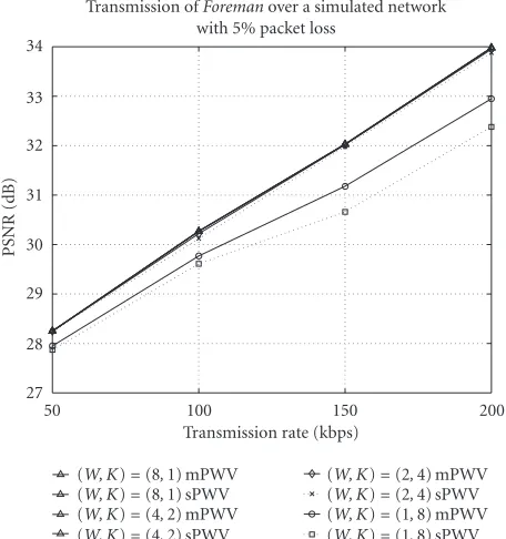
Figure 11shows the same results as inFigure 10, but with
a different packet loss rate of 5%. The maximum
perfor-mance difference is about 0.5 dB, which happens in pure
200
Transmission ofForemanover a simulated network with 20% packet loss
(W, K)=(8,1) mPWV Figure10: Simulation results using error control for transmitting mPWV and sPWV codedForemanover a network with 20% packet loss.
Transmission ofForemanover a simulated network with 5% packet loss
(W, K)=(8,1) mPWV Figure11: Simulation results using error control for transmitting mPWV and sPWV codedForemanover a network with 5% packet loss.
FEC case at the highest rate. With a small packet loss rate of
200
Transmission of Akiyo over a simulated network with 20% packet loss
(W, K)=(8,1) mPWV Figure12: Simulation results using error control for transmitting mPWV and sPWV coded Akiyo over a network with 20% packet loss.
Transmission of Akiyo over a simulated network with 5% packet loss
(W, K)=(8,1) mPWV Figure13: Simulation results using error control for transmitting mPWV and sPWV coded Akiyo over a network with 5% packet loss.
achieves performance very close to higherW =4 andW =
8 cases. This substantiates our analysis result as shown in Figure 9.
Table1: Numbers of subscribed source packets of all four layers in the transmission of PWV codedForemanusing pure FEC with a packet loss rate of 20% at four different transmission rates.
Rtotal(kbps) 50 100 150 200
Ptotal(packets) 8 16 24 32
Table2: Numbers of subscribed source packets of all four layers in the transmission of PWV codedForemanusing hybrid FEC/pseudo-ARQ ((W, K)=(2,4)) with a packet loss rate of 20% at four diff er-ent transmission rates.
Rtotal(kbps) 50 100 150 200
Ptotal(packets) 8 16 24 32
The simulation results using Akiyo are presented in Figure 12for 20% packet loss rate and inFigure 13for 5% packet loss rate, respectively. Average PSNRs of two sets of simulations based on single-layered PWV coding and mul-tilayered PWV coding are presented. The maximal gain in pure FEC is 0.53 dB for 20% packet loss rate and 0.48 for 5% packet loss rate. Because the Akiyo sequence contains much
less high-frequency components than Foreman, packets in
higher-frequency layers have a smaller contribution to the re-duction of distortion. As a result when pseudo-ARQ is used
(W =2,4,8), the subscription policy tends to spend more
on channel coding part instead of increasing the source rate. Thus, there is very little packet loss in pseudo-ARQ cases, and the performance of the two error-control schemes are almost the same.
Table 1lists the number of subscribed source packets of
all four layers in the transmission of PWV coded Foreman
using pure FEC with a packet loss rate of 20%. Note that Rtotal is the total transmission rate in kbps. AndPtotalis the
corresponding number of 1000-byte packets at rate Rtotal.
The number of subscribed source packets of the ith layer
is denoted by Si (i = 1,2,3,4). These numbers are
deter-mined by the UEP algorithm described inSection 4. From
20
Figure14: Rate allocationN∗in pure FEC when the transmission rate is 200 kbps and the packet loss ratio is 20%.
200
Transmission ofForemanover a simulated network with 20% packet loss
(W, K)=(8,1) PWV Figure15: Simulation results using error control for transmitting PWV and 3D SPIHT coded Foreman over a network with 20% packet loss.
Table 2 depicts the number of subscribed source
pack-ets of all four layers in the transmission of PWV coded
Fore-manusing hybrid FEC/pseudo-ARQ ((W, K)=(2,4)) with
a packet loss rate of 20%. Although the FEC/pseudo-ARQ
solution degenerates to the FEC solution when W = 1
(e.g., no ARQ); whenW > 1, a receiver is allowed to
sub-scribe to more source packets, taking advantage of hybrid
FEC/pseudo-ARQ. The difference in S3andS4between
re-sults in the two tables highlights this point.
Figure 14depicts the rate allocationN∗used in our pure
FEC simulations ofForemanwhen the transmission rate is
200 kbps (or 32 packets per GOF). A receiver subscribes to a total of 20 source sublayers and 256 source/parity packets for
K=8 GOFs in this case.
Finally, we also compare the performance difference
be-tween our PWV-based error-control strategy and the ap-proach in [17] using 3D SPIHT. The average PSNRs in
sim-ulations ofForemanare computed and plotted inFigure 15
for 20% packet loss rate at four different transmission rates.
Results of pure FEC, as a special case of hybrid
FEC/Pseudo-ARQ whenW=1, shows that our multilayered
scheme using PWV outperforms the single-layered approach in [17] using 3D SPIHT with a gain up to 2.2 dB. In the case of hybrid FEC/Pseudo-ARQ, there is also a corresponding gain of up to 1.6 dB, which mainly comes from the
higher-efficient encoding. The gap between the hybrid method and
pure FEC is between 0.8 and 1.8 dB.
8. SUMMARY
We present an integrated approach toward combined source coding and error-control design for RLM of video based on the PWV source coder and RS erasure channel codes. Both analysis and simulations show gains of our integrated frame-work over previous frame-work. The practical gain stems from the fact that the PWV source coder achieves better R-D perfor-mance than 3D SPIHT and that our new multilayered error control mechanism based on the PWV bitstream is superior to the single-layered one in [17].
In this paper, we assume that a separate congestion con-trol mechanism is carried out at each receiver to determine the available bandwidth in RLM. Further work incorporat-ing quality adaptation into our combined source codincorporat-ing and error control framework would be desirable. We also assume that packet loss is random in the network, which does not hold in many situations. Designing error control for trans-mitting video over networks with burst packet loss should be also considered as a future work.
ACKNOWLEDGMENTS
The authors gratefully acknowledge Jianping Hua’s assis-tance in the PWV coder design. This work supported by the National Science Foundation (NSF) Career grant MIP-00-96070, the NSF grant CCR-01-04834, the Army Research
Of-fice (ARO) YIP grant DAAD19-00-1-0509, and the Office of
Naval Research (ONR) YIP grant N00014-01-1-0531.
REFERENCES
[1] “Special issue on real-time video over the Internet,” Signal Processing: Image Communication, vol. 15, September 1999. [2] “Special issue on multimedia over IP,” IEEE Trans.
Multime-dia, vol. 3, March 2001.
[4] ISO/IEC JTC 1/SC29/WG11 N2687, “MPEG-4 Video Verifi-cation Model Version 13.0,” March 1999.
[5] ITU-T Recommendation H.263, version 2, “Video coding for low bitrate communication,” January 1998.
[6] B.-J. Kim, Z. Xiong, and W. A. Pearlman, “Low bit-rate scal-able video coding with 3D set partitioning in hierarchical trees (3D SPIHT),”IEEE Trans. Circuits and Systems for Video Tech-nology, vol. 10, no. 8, pp. 1365–1374, 2000.
[7] H. Radha, M. van der Schaar, and Y. Chen, “The MPEG-4 fine-grained scalable video coding method for multimedia streaming over IP,”IEEE Trans. Multimedia, vol. 3, no. 1, pp. 53–68, 2001.
[8] S. Paul, Multicasting on the Internet and Its Applications, Kluwer Academic, Boston, Mass, USA, 1998.
[9] S. Servetto and K. Nahrstedt, “Broadcast quality video over IP,”IEEE Trans. Multimedia, vol. 3, no. 1, pp. 162–173, 2001. [10] S. R. McCanne, Scalable compression and transmission of In-ternet multicast video, Ph.D. thesis, University of California, Berkeley, Calif, USA, December 1996.
[11] D. Chiu and R. Jain, “Analysis of the increase and decrease algorithms for congestion avoidance in computer networks,” Journal of Computer Networks and ISDN, vol. 17, no. 1, pp. 1–14, 1989.
[12] R. Rejaie, M. Handley, and D. Estrin, “Layered quality adap-tation for Internet video streaming,” IEEE Journal on Se-lected Areas in Communications, vol. 18, no. 12, pp. 2530– 2544, 2000.
[13] J. Lu, A. Nosratinia, and B. Aazhang, “Progressive source-channel coding of images over bursty error source-channels,” in Proc. International Conference on Image Processing, Chicago, Ill, USA, October 1998.
[14] M. Ruf and J. Modestino, “Operational rate-distortion perfor-mance for joint source and channel coding of images,” IEEE Trans. Image Processing, vol. 8, no. 3, pp. 305–320, 1999. [15] V. Chande, H. Jafarkhani, and N. Farvardin, “Joint
source-channel coding of images for source-channels with feedback,” inProc. IEEE Information Theory Workshop, San Diego, Calif, USA, February 1998.
[16] J. Hagenauer, “Rate-compatible punctured convolutional codes (RCPC codes) and their applications,” IEEE Trans. Communications, vol. 36, no. 4, pp. 389–400, 1988. [17] P. A. Chou, A. E. Mohr, A. Wang, and S. Mehrotra,
“Er-ror control for receiver-driven layered multicast of audio and video,” IEEE Trans. Multimedia, vol. 3, no. 1, pp. 108–122, 2001.
[18] T. Chu and Z. Xiong, “Combined wavelet video cod-ing and error control for Internet streamcod-ing and multicast,” inProc. GlobeCom ’01, San Antonio, Tex, USA, November 2001.
[19] T. Chu, J. Hua, and Z. Xiong, “Packetized wavelet video cod-ing and error control for receiver-driven layered multicast: an integrated approach,” inProc. Multimedia Signal Processing Workshop, Cannes, France, October 2001.
[20] J. Hua, Z. Xiong, and X. Wu, “High-performance 3-D embed-ded wavelet video (EWV) coding,” inProc. Multimedia Signal Processing Workshop, Cannes, France, October 2001. [21] X. Wu, S. Cheng, and Z. Xiong, “On packetization of
embed-ded multimedia bitstreams,” IEEE Trans. Multimedia, vol. 3, no. 1, pp. 132–140, 2001.
[22] L. Rizzo, “Effective erasure codes for reliable computer com-munication protocols,” ACM Computer Communication Re-view, vol. 27, no. 2, pp. 24–36, 1997.
[23] J. Byers, M. Luby, M. Mitzenmacher, and A. Rege, “A dig-ital fountain approach to reliable distribution of bulk data,”
in Proc. ACM SIGCOMM ’98, pp. 56–67, Vancouver, BC, Canada, September 1998.
[24] W.-T. Tan and A. Zakhor, “Real-time Internet video using er-ror resilient scalable compression and TCP-friendly transport protocol,”IEEE Trans. Multimedia, vol. 1, no. 2, pp. 172–186, 1999.
[25] S. Servetto and K. Nahrstedt, “Video streaming over the pub-lic Internet: Multiple description codes and adaptive trans-port protocols,” inProc. IEEE International Conference on Im-age Processing, vol. 3, Kobe, Japan, October 1999.
[26] R. Puri, K. Lee, K. Ramchandran, and V. Bharghavan, “An in-tegrated source transcoding and congestion control paradigm for video streaming in the Internet,”IEEE Trans. Multimedia, vol. 3, no. 1, pp. 18–32, 2001.
[27] B. G. Haskell, A. Puri, and A. N. Netravali, Digital Video: An Introduction to MPEG-2, Chapman & Hall, New York, NY, USA, 1997.
[28] L. Yang, F. C. M. Martins, and T. R. Gardos, “Improving H.263+ scalability performance for very low bit rate applica-tions,” inProc. Visual Communications and Image Processing, San Jose, Calif, USA, January 1999.
[29] S. Li, F. Wu, and Y.-Q. Zhang, “Study of a new approach to improve FGS video coding efficiency,” inISO/IEC MPEG 50th meeting, M5583, Maui, Hawaii, USA, December 1999. [30] E. Steinbach, N. Farber, and B. Girod, “Standard
compati-ble extension of H.263 for robust video transmission in mo-bile environments,”IEEE Trans. Circuits and Systems for Video Technology, vol. 7, no. 6, pp. 872–881, 1997.
[31] G. Karlsson and M. Vetterli, “Three dimensional subband coding of video,” inProc. IEEE Int. Conf. Acoustics, Speech, Signal Processing, pp. 1100–1103, New York, NY, USA, April 1988.
[32] D. Taubman and A. Zakhor, “Multirate 3-D subband coding of video,”IEEE Trans. Image Processing, vol. 3, no. 5, pp. 572– 588, 1994.
[33] J. R. Ohm, “Three-dimensional subband coding with motion compensation,”IEEE Trans. Image Processing, vol. 3, no. 5, pp. 559–571, 1994.
[34] S. J. Choi and J. W. Woods, “Motion compensated 3-D sub-band coding of video,” IEEE Trans. Image Processing, vol. 8, no. 2, pp. 155–167, 1999.
[35] A. Said and W. A. Pearlman, “A new, fast, and efficient image codec based on set partitioning in hierarchical trees,” IEEE Trans. Circuits and Systems for Video Technology, vol. 6, no. 3, pp. 243–250, 1996.
[36] D. Taubman, “High performance scalable image compression with EBCOT,”IEEE Trans. Image Processing, vol. 9, no. 7, pp. 1158–1170, 2000.
[37] M. Antonini, M. Barlaud, P. Mathieu, and I. Daubechies, “Im-age coding using wavelet transform,” IEEE Trans. Image Pro-cessing, vol. 1, no. 2, pp. 205–220, 1992.
[38] Y. Shoham and A. Gersho, “Efficient bit allocation for an ar-bitrary set of quantizers,” IEEE Trans. Acoustics, Speech, and Signal Processing, vol. 36, no. 9, pp. 1445–1453, 1988. [39] W.-T. Tan and A. Zakhor, “Video multicast using layered FEC
and scalable compression,” IEEE Trans. Circuits and Systems for Video Technology, vol. 11, no. 3, pp. 373–386, 2001. [40] J. Nonnenmacher, E. Biersack, and D. Towsley, “Parity-based
loss recovery for reliable multicast transmission,”IEEE Trans. Networking, vol. 6, no. 4, pp. 349–361, 1998.
Tianli Chu received the B.Eng. degree in telecommunication and information sys-tems from Tsinghua University, China, in 1999, and the M.S. degree in electrical en-gineering in 2002 from Texas A&M Univer-sity, College Station, where he is currently working toward the Ph.D. degree in the De-partment of Electrical and Computer En-gineering. His research interests are image and video coding, multimedia communica-tion, and information theory.
Zixiang Xiongreceived the Ph.D. degree in electrical engineering in 1996 from the Uni-versity of Illinois at Urbana-Champaign. From 1997 to 1999, he was with the Univer-sity of Hawaii. Since 1999, he has been with the Department of Electrical Engineering at Texas A&M University, where he is an As-sociate Professor. He spent the summers of 1998 and 1999 at Microsoft Research, Red-mond, WA, and the summers of 2000 and