ISSN(Online): 2319-8753 ISSN (Print) : 2347-6710
I
nternational
J
ournal of
I
nnovative
R
esearch in
S
cience,
E
ngineering and
T
echnology
(A High Impact Factor, Monthly, Peer Reviewed Journal)Visit: www.ijirset.com
Vol. 6, Issue 10, October 2017
Enhancement of Transient Stability by using
Bridge-Type Fault Current Limiter in Doubly
Fed Induction Machine-Based Wind
Generator
S.Sowmya1, E.Nagabhushana 2, C. Viswanath3
M.Tech Student, Dept. of EEE, BIT Institute of Technology, JNTUA, AP, India1
Associate Professor, Dept. of EEE, BIT Institute of Technology, JNTUA, AP, India2
Associate Professor & HOD, Dept. of EEE, BIT Institute of Technology, JNTUA, AP, India3
ABSTRACT: In this paper Transient stability is a major sympathy toward doubly fed induction machine (DFIM).A
DFIM-based wind generator is promptly influenced by shortcomings at the network side as its stator windings are interfaced to grid. Be that as it may, the wind generators need to stay connected and proceed with operation during flaws at the grid side as indicated by the network code prerequisites. Along these lines, it is imperative to improve the transient soundness of the DFIM-based wind generators. To accomplish upgraded transient steadiness of the DFIM, a bridge type fault current limiter (BFCL) is proposed through FLC in this paper. Symmetrical as well as unsymmetrical faults were applied to test system efficiency of the BFCL in transient stability enhancement. Simulations were carried out in Matlab/Simulink environment. To demonstrate the effectiveness of the proposed BFCL ,its performance is compared with series dynamic braking resistor(SDBR). Simulation results of BFCL gives better stabilization of DFIM.
KEYWORDS: BFCL,SDBR, Doubly Fed Induction Machine (DFIM, Rotor-Side Converter (RSC) and Grid Side
Converter (GSC),Fuzzy Logic Controller(FLC)..
I. INTRODUCTION
Technological advancement and industrialization has brought the expansion up in electrical power demand all around the globe. Quick fatigue and restricted store of fossil powers, escalation of natural concerns have made it dire to look for alternative energy sources and to devise enhanced techniques for abusing renewable energy sources. Among the available renewable energy sources, wind energy is the quickest developing and most noticeable choice to create electric power because of its zero fuel cost, no carbon discharge, lower maintenance, and cleaner, less expensive and renewable nature. It is assessed that around 10% of worldwide power interest will be supplied from the wind energy by the year 2020. Because of adaptability in operation and upgraded highlights like higher output power, higher proficiency, enhanced power quality, variable pace operation, lower mechanical weight on turbine subsequently bring down support, decoupled control of the active and reactive power, the variable rate wind generators are getting to be favored decision for new establishments and drawing higher consideration than the conventional impelling machine-based altered rate wind generators. Lower cost, sturdiness, basic structure, probability to cover an extensive variety of wind rate, in part evaluated variable frequency ac/dc/air conditioning converter and lower switching loss have made the doubly sustained incitement machine (DFIM) a better decision over the other wind generator choices.
grid by means of the rotor-side converter (RSC) and the grid side converter (GSC) that are connected consecutive through a dc-link capacitor. At the occasion of system deficiency, terminal voltage of the DFIM goes low and high current moves through both stator and rotor winding. This is a danger to stable operation and may inevitably blaze the machine and the converters. Customarily, to shield from such blame occurrences, wind generators were detached from the grid. The converter of the DFIM topology has the control capacity to keep up solidness at flaw condition. Since the converters have fractional rating, their ability alone is deficient to guarantee dependability. A helper gadget like static synchronous compensator is proposed yet it needs extra converter, coupling transformer and symphonious channels. Energy stockpiling systems like flywheel energy stockpiling, superconducting attractive energy stockpiling and superconducting deficiency current limiter are additionally proposed, however the high establishment cost counterbalances their great execution.
The bridge type fault current limiter (BFCL) is another method with promising applications in power systems and issue ride through ability improvement of altered speed wind turbine generators. Be that as it may, the BFCL is never connected to improve the transient solidness of DFIM-based wind generators. In this study, execution of the BFCL on upgrading the transient stability of the DFIM in wind energy application is researched. The effectiveness of the proposed BFCL is shown through a test wind energy conversion system. The system comprises of a wind turbine furnished with a DFIM, a transformer and the double circuit transmission lines connected with the boundless bus. Transitory symmetrical and unsymmetrical shortcomings were connected at the most powerless purpose of the system. Where ωr is the angular mechanical speed. The wind turbine
Fig: 1 Basic diagram of the DFIM with the test system.
II. WIND TURBINE AND DFIM MODELING
A solitary mass system is considered for the demonstrating of the wind turbine. The turbine mechanical part progression is dismissed because of little span of the considered deficiencies. The DFIM itself is fundamentally an actuation generator with the stator windings directly connected with grid and open rotor windings connected with the grid through the ac/dc/ac converter as appeared in Fig. 1. Fig. 1 likewise demonstrates the one line graph of the test system model alongside the line parameters. A 2-MW DFIM is connected with the point of common coupling (PCC) through a phase up transformer. The PCC is connected with network through double circuit transmission line. The BFCL is connected in series with one of the transmission lines to secure it as appeared in Fig. 1. The SDBR is likewise connected at the same point in comparative style. Displaying of the wind turbine, the DFIM and the converter controllers are outlined in the consequent segments.
A. Wind Turbine Modeling
ISSN(Online): 2319-8753 ISSN (Print) : 2347-6710
I
nternational
J
ournal of
I
nnovative
R
esearch in
S
cience,
E
ngineering and
T
echnology
(A High Impact Factor, Monthly, Peer Reviewed Journal)Visit: www.ijirset.com
Vol. 6, Issue 10, October 2017
---- (1)
Where Pw is the extracted power from the wind, ρ is the air density, R is the blade radius, Vw is the wind velocity, and Cp is the power coefficient which is a function of both the tip speed ratio λ, and the blade pitch angle β and it is given by
---(2)
---(3)
Where ωr is the angular mechanical speed. The wind turbine parameters used in this study.
B. DFIM Modeling
Many works like have portrayed the demonstrating of the DFIM. The Park's change model, which is basically the fifth-order two-axis representation is displayed the DFIM. A synchronously turning d − q reference edge is utilized with its d-hub adjusted to the stator flux. A decoupled control between the rotor excitation current and the electrical torque is gotten. Thusly, the reference angle is turning with the same pace as the stator flux.
C. RSC Controller
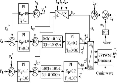
The RSC is a two-level, six-beat, Insulated gate bipolar transistor (IGBT) [CM200HG-130H] based full extension power electronic ac/dc converter that couples the rotor side to the dc link. The RSC controller takes the terminal active power Pt, the reactive power Qt and the terminal voltage Vt as inputs and controls the output active and reactive power. It utilizes the proportional integral (PI) controllers to deliver fitting three phase (SVPWM) signal generator square, with the goal that it can create beats for the IGBT switches of the RSC. The Park's change is utilized to change over three phase amounts into proportional d − q parts and the other way around. The slip edge is produced by looking at the rotor position and the terminal voltage angle with the assistance of the phase-locked loop (PLL), and the slip is utilized as change point as a part of the Park's change square. Amounts with "*" referee to reference value as appeared in Fig. 2.
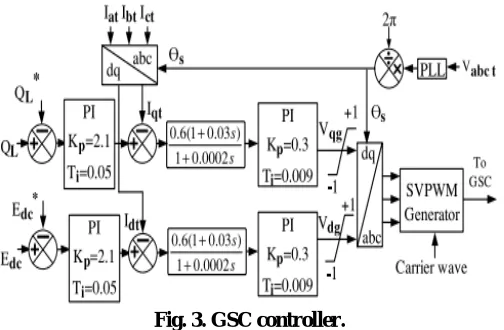
Fig. 3. GSC controller.
reference signal for space vector pulse width modulation (SVPWM) signal generator block, so that it can generate pulses for the IGBT switches of the RSC [27]. The Park’s transformation is used to convert three phase quantities into equivalent d−q components and vice versa. The slip angle is generated by comparing the rotor position and the terminal voltage angle with the help of the phase-locked loop (PLL), and the slip is used as transformation angle in the Park’s transformation block. Quantities with “*” refer to reference value as shown in Fig. 2.
D. GSC Controller
The GSC also contains a two-level, six-pulse, IGBT [CM200HG-130H] based full bridge power electronic ac/dc converter with the dc side connected to the dc link and the ac side interfaced to the grid. This converter essentially helps maintain a constant power factor at the connection point. It is
important to choose an appropriate switching frequency to keep the harmonics to the minimum level. A frequency of 1650 Hz is chosen as it is an odd multiple of the third harmonic and can minimize up to thirteenth harmonics. The GSC controller scheme is given in Fig. 3. It takes the dc link voltage Edc and the rotor line reactive power QL as inputs and produces the necessary outputs so that the SVPWM pulse generator can generate required pulses for the GSC converter. Also, by maintaining a constant dc-link voltage, the controller ensures the energy balance on the both sides of the dc link.
III. BFCL
BFCL Configuration
The BFCL is composed of two sections, namely the bridge
ISSN(Online): 2319-8753 ISSN (Print) : 2347-6710
I
nternational
J
ournal of
I
nnovative
R
esearch in
S
cience,
E
ngineering and
T
echnology
(A High Impact Factor, Monthly, Peer Reviewed Journal)Visit: www.ijirset.com
Vol. 6, Issue 10, October 2017
Fig. 5. BFCL controller
BFCL Operation
During normal operating condition of the system, the IGBT switch in the bridge part remains closed. For one half cycle of
electrical frequency, theD1-Ldc-Rdc-D4 path carries the line current and for the other half it is carried byD2-Ldc-Rdc-D3.
So, the current through Ldc, flows in the same direction and this current is the dc current idc. Ldc is charged to the peak current and offers no impedance to idc. The dc reactor inherited resistance, the IGBT turn-on resistance and the diode forward voltagedrop cause some voltage drop, but this voltage drop is quite negligible compared to line drop and has ignorable significance. So the bridge has no impact on normal or steady state operation.
IV. SDBR
In this study, so as to exhibit the effectiveness of the proposed BFCL arrangement, its execution is contrasted and that of the SDBR as shown in Fig.6. The SDBR is a demonstrated innovation, and past studies demonstrated that it can upgrade transient strength and enhance issue ride through ability of the wind generator systems.
SDBR Configuration
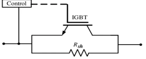
The SDBR is modeled by arranging a resistor with a parallel switch as shown in Fig. 6. This study considers this switch to be the IGBT based, due to its fast response and modular design.
Fig. 6. Single phase SDBR topology
B. SDBR Operation
IGBT switches bypassing the braking resistors. At the event of fault, the line currents tend to rise very sharply. The shunt resistor will be dynamically inserted into the network by opening the IGBT switch. The fault current will then flow through the inserted resistor and the resistor will continue to be in the circuit until a desired voltage Vref is achieved at PCC. As Vpcc passes Vref, the IGBT will be closed and the circuit will return to its normal state.
V. SIMULATION RESULTS
A. Without Controller 1LG
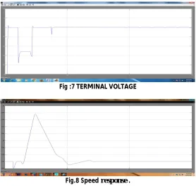
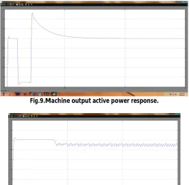
The below figures 7,8,9,10 shows without controller 1LG.It is seen that the voltage level drops around 0.7 p.u. The machine speed goes low right after the fault instant rises with no controller same as 3LG. The active power fluctuation is lowest and demand of machine power is highest from fault initialization to breaker opening. DC link voltage is not much stable in this case.
Fig :7 TERMINAL VOLTAGE
ISSN(Online): 2319-8753 ISSN (Print) : 2347-6710
I
nternational
J
ournal of
I
nnovative
R
esearch in
S
cience,
E
ngineering and
T
echnology
(A High Impact Factor, Monthly, Peer Reviewed Journal)Visit: www.ijirset.com
Vol. 6, Issue 10, October 2017
Fig.9.Machine output active power response.
Fig.10.Vdc.
B. Without Controller 3LG
In below figures 11,12,13,14 shows without controller for 3LG. It is seen that the voltage goes very low right after fault is initiation and even goes lower till breaker opens. Machine speed goes high and may cause instability due to long fault duration. The active power demand of machine becomes very close to zero after the fault instant and remain same till breaker is open. When breaker is open it causes large imbalance of output power without any controller action. DC link voltage can be maintained constant.
Fig.12 Speed response
Fig.13 Machine output active power.DC link voltage response
Fig.14. DC link voltage response
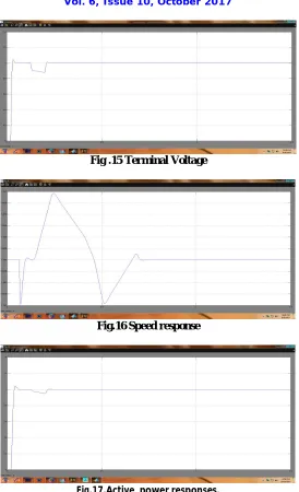
C. SDBR 1LG
ISSN(Online): 2319-8753 ISSN (Print) : 2347-6710
I
nternational
J
ournal of
I
nnovative
R
esearch in
S
cience,
E
ngineering and
T
echnology
(A High Impact Factor, Monthly, Peer Reviewed Journal)Visit: www.ijirset.com
Vol. 6, Issue 10, October 2017
Fig .15 Terminal Voltage
Fig.16 Speed response
Fig.18 DC link voltage
D. SDBR 3LG
In below figures 19,20,21,22,23 shows SDBR 3LG. It is seen that SDBR cannot maintain voltage levels to 0.9 p.u also after the breaker opening terminal voltage comes back to nominal value faster with the help of BFCL. Machine speed gives lower oscillation and faster stabilization. It is noticeable that right after fault initiation machine speed drops and rises sharply. Directional speed variation is threatening the mechanical system. The active power suddenly goes high and goes low which is harmful for machine. The breaker opening action rise output power with SDBR operation. The SDBR consumes no active power during normal operation which clearly shows that it has no effect on system during normal operation. DC line voltage can be maintained constant but not much as BFCL.
Fig.19 Terminal voltage
ISSN(Online): 2319-8753 ISSN (Print) : 2347-6710
I
nternational
J
ournal of
I
nnovative
R
esearch in
S
cience,
E
ngineering and
T
echnology
(A High Impact Factor, Monthly, Peer Reviewed Journal)Visit: www.ijirset.com
Vol. 6, Issue 10, October 2017
Fig.21.Active power response.
Fig.22 Sdbr voltage.
Fig.23 DC link voltage
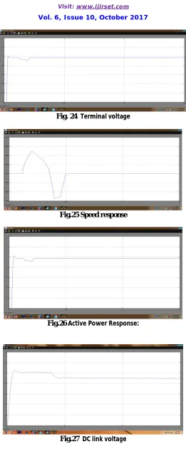
E. BFCL 1LG
Fig. 24 Terminal voltage
Fig.25 Speed response
Fig.26 Active Power Response:
ISSN(Online): 2319-8753 ISSN (Print) : 2347-6710
I
nternational
J
ournal of
I
nnovative
R
esearch in
S
cience,
E
ngineering and
T
echnology
(A High Impact Factor, Monthly, Peer Reviewed Journal)Visit: www.ijirset.com
Vol. 6, Issue 10, October 2017
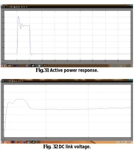
F. BFCL 3LG:
In below figures 28,29,30,31,32 shows BFCL 3LG. It is seen that voltage level of BFCL keeps 0.1 p.u of nominal value which indicates BFCL is more sensitive and faster respond to fault and gives better voltage stabilization than SDBR. The BFCL limits the rate of rising of machine speed and ensures better stability than SDBR because it totally prevented by application of BFCL. The output power demand to the machine is highest with low fluctuation at fault and breaker opening instant. Faster stabilization of output power is also provided with BFCL . It consumes more active power than SDBR from fault intiation to breaker opening instant and gives better transient stability. It is also noticeable that BFCL has no active power during normal operation. It is possible to maintain more constant dc link voltage and GSC controller works well in conjunction with BFCL.
Fig.28 Terminal voltage
Fig.29 Speed response.
Fig.31 Active power response.
Fig. 32 DC link voltage.
G. BFCL EXTENSION 3LG
In below figures 33,34,35,36,37 shows BFCL 3LG using FLC. It is seen that voltage level of BFCL keeps rated nominal value which indicates BFCL is more sensitive and faster respond to fault and gives better voltage stabilization than BFCL using PI controller. The BFCL limits the rate of rising of machine speed and ensures better stability because it totally prevented by application of BFCL using FLC. The output power demand to the machine is lowest with low fluctuation at fault and breaker opening instant. Faster stabilization of output power is also provided with BFCL . It consumes less active power than BFCL using PI controller from fault intiation to breaker opening instant and gives better transient stability. It is also noticeable that BFCL has no active power during normal operation. It is possible to maintain more constant dc link voltage .
ISSN(Online): 2319-8753 ISSN (Print) : 2347-6710
I
nternational
J
ournal of
I
nnovative
R
esearch in
S
cience,
E
ngineering and
T
echnology
(A High Impact Factor, Monthly, Peer Reviewed Journal)Visit: www.ijirset.com
Vol. 6, Issue 10, October 2017
Fig.34 Speed
Fig.35 Active power
Fig.37 DC link voltage.
H. BFCL EXTENSION FOR1LG
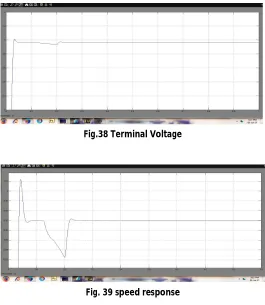
In below figures 38,39,40,41 shows BFCL1LG using FLC. It is seen that BFCL can maintain voltage at rated level properly. The BFCL using FLC performance is better than BFCL using PI. The machine speed oscillation is kept to lowest and variation is minimum so machine is well stable with application of BFCL. The output active power fluctuation is lowest and active power demand is highest from fault initiation to breaker opening with application of BFCL. Here DC link voltage retain more stable voltage than BFCL using PI controller.
Fig.38 Terminal Voltage
ISSN(Online): 2319-8753 ISSN (Print) : 2347-6710
I
nternational
J
ournal of
I
nnovative
R
esearch in
S
cience,
E
ngineering and
T
echnology
(A High Impact Factor, Monthly, Peer Reviewed Journal)Visit: www.ijirset.com
Vol. 6, Issue 10, October 2017
Fig.40 active power
Fig.41 Dc link voltage.
VII. CONCLUSION
The application of the BFCL to enhance the transient stability of DFIM is proposed in this paper. The performance of the proposed BFCL is compared with that of the SDBR. From the simulation results, the BFCL is a very effective means to enhance the transient stability of the DFIM-based variable speed wind generator and the BFCL can help the DFIM-based wind farms abide by the grid code requirements. The SDBR is outperformed by the BFCL in every aspect, as seen from graphical and numerical results. In the proposed BFCL FLC is used instead of PI controller. The proposed system gives better performance and characteristics compared to existing. In our future study, a high capacity variable speed wind farm connected to a large power system will be considered. Further rmore, an optimal design of the BFCL will be developed considering variable values of the shunt impedance.
REFERENCES
[1] P. Musgrove, Wind Power. Cambridge, U.K.: Cambridge Univ. Press,2010.
[2] B. Singh, P. Jayaprakash, T. R. Somayajulu, and D. P.Kothari, “Reducedrating VSC with a zig-zag transformer for current compensationin a three-phase four-wire distribution system,” IEEE Trans. PowerDel., vol. 24, no. 1, pp. 249– 259, Jan. 2009.
[3] R. M. Ciric, L. F. Ochoa, A. Padilla-Feltrin, and H.Nouri, “Fault analysisin four-wire distribution networks,”Proc. Inst. Elect. Eng., Gen.,Transm. Distrib., vol. 152, no. 6, pp. 977–982, 2005.
[4] J. C. Meza and A. H. Samra, “Zero-sequence harmonics current minimizationusing zero-blocking reactor and zig-zag transformer,” in Proc.IEEE DRPT, 2008, pp. 1758–1764.
[5]H. L. Jou, J. C.Wu,K.D.Wu,W. J. Chiang, andY. H. Chen, “Analysisof zig-zag transformer applying in the three-phase four-wire distribution power system,” IEEE Trans. Power Del., vol. 20, no. 2, pt. 1, pp.1168–1178, Apr. 2005.
[7] P. La Seta and P. Schegner, “New control scheme for doubly-fed induction generators to improve transient stability,”
[8] P.La Seta and P. Schegner, “Comparison of stabilizing methods for doubly fed induction generators for wind turbines,” in Proc. Int. Conf. Futur.Power Syst., Nov. 2005, Paper W045, Conference CDROM.
[9] M. Rahimi and M. Parniani, “Transient performance improvement of windturbines with doubly fed induction generators using nonlinear controlstrategy,” IEEE Trans. Energy Convers., vol. 25, no. 2, pp. 514–525, Jun.2010.
[10] A.D.Hansen and L. H. Hansen, “Wind turbine conceptmarket penetrationover 10 years (1995–2004),” Wind Energy, vol. 10, pp. 81–97, Jan. 2007.
[11] M. Tsili and S. Papathanassiou, “A review of grid code technical requirementsfor wind farms,” IET Renew. Power Gener., vol. 3, no. 3, pp.308– 332, 2009.
[12] Z. Chen and H. Li, “Overview of different wind generator systems and their comparisons,” IET Renew. Power Gener., vol. 2, pp. 123–138, Jun. 2008.
BIOGRAPHY
Miss.S.SOWMYA received B.Tech degree in Electrical &Electronics Engineering from JNTU, Anantapur University and studying Master's degree in Electrical Power Systems in BIT Institute of Technology, Hindupur affiliated to JNTU Anantapur, A.P
Mr. E.NAGABHUSHANA presently working as Associate professor in B.I.T institute of Technology ,Hindupur, Andhra Pradesh, India. Completed his M.Tech in Energy Systems from JNTU-A University, Anantapur and B.Tech from SITAMS college of engineering ,Chittoor. His fields of interest include Non Conventional Energy Sources, Advanced Control Techniques in Power Systems and electrical machines.