Dynamic Modelling and Performance Analysis
of a Line-start Interior Permanent Magnet
Synchronous Motor
Onah. C. O.
1, Obe. E. S.
2, Agber. J. U.
3Lecturer, Department of Electrical and Electronics Engineering, University of Agriculture, Makurdi, Nigeria1 Professor, Department of Electrical and Electronics Engineering, University of Nigeria, Nsukka2 Professor, Department of Electrical and Electronics Engineering, University of Agriculture, Makurdi, Nigeria3
ABSTRACT:The inherent advantages of line-start permanent magnet synchronous motor such as high efficiency, high power factor and high power density, distinguish it as a preferred candidateto the conventional induction motor in many applications. Thus, this paper sets forth the performance analysis of a line-start interior permanent magnet synchronous motor (LSIPMSM). The main focus of the paper is to derive a mathematical model for investigating the performance of a line-start interior permanent magnet synchronous motor. A dynamic d-q model of the motor is also presented and the model simulated using an embedded MATLAB function. The start-up and the synchronization performance of the LSIPMSM for the load variations are obtained in MATLAB/Simulink. The results of simulation indicated that the LSIPMSM has good starting capability, high efficiency and high torque. Further investigation into the performance of the modelled LSIPMSM reveals that the motor runs in constant speed irrespective of the change in loads during its operation.
KEYWORDS:LSIPMSM, MATLAB Function, Power Factor, Speed, Synchronization, Torque density.
I. INTRODUCTION
A line-start permanent magnet synchronous motor has magnets embedded in its rotor which provides the synchronous excitation and a rotor cage provides induction motor torque for starting. Thus, it is a high efficiency synchronous motor with self-starting capability when operating from a fixed frequency voltage source [1]. The interest in line-start permanent magnet synchronous motor is present in a wide area of application, ranging from high performance servo drives to line-start applications, such as fans and pumps. These motors are already replacing synchronous reluctance motors in applications, where it is important to have a number of machines operating synchronously with each other [2]. The line-start capability of these motors allows individual motors to be taken out of service and replaced without stopping the operation of any other motor.
LSPMSM has additional feature that makes it to start from standstill, which makes it an attractive candidate for the sensorless control drive system. Line start interior permanent magnet (IPM) motor has high power factor, high torque density and runs in constant speed irrespective of the effect of load variation and it requires no inverter fed ac supply, thus improving the overall efficiency of the system.
MATLAB/Simulink package. Our research includes the development of a d-q model of both stator and the squirrel cage in order to analyze the run up response of the proposed motor.
II. MODELLINGOFLINESTARTIPMSM
2.1 Structure of the IPMSM
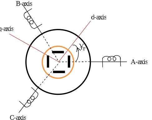
A conceptual cross-sectional view of a three-phase, 4-pole IPM synchronous motor along with two reference frames is as shown in Fig. 1. The stator reference axis for the A-phase is chosen to the direction of maximum mmf when a positive A-phase current is supplied at its maximum level. Reference axis for B- and C- stator frame are chosen to be 120 and 240 (electrical angle) ahead of the A-axis, respectively. Following the convention of choosing the rotor reference frame, the direction of permanent magnet flux is chosen as the d-axis, while the q-axis is 90 degrees ahead of the d-axis. The angle of the rotor d-axis with respect to the stator A-axis is defined as
r. Note that as the machineturns, the d-q reference frame is rotating at a speed of
dt
d
, while the stator A-,B-,C- axes are fixed in space. Itisestablished that the choice of this rotating frame greatly simplifies the dynamic equations of the model.
Fig. 1 Schematic diagram of IPMSM
2.2 Dynamic Model of LSIPMSM
In the face of wide industrial use of inverter for variable voltage and variable frequency supply to PMSM, line-start operation of permanent magnet synchronous motors is still highly relevant in medium, low and fractional horsepower applications. Therefore, this section finds it indispensable to model PMSM from busbar voltages so as to investigate its performance [1, 6, 7]. A rotor cage is employed to help start the motor on a fixed frequency supply. The motor starts as an induction motor due to the resultant of two torque components i.e. cage torque and magnet opponent torque (braking torque). When the motor speed reaches near synchronous speed, a synchronization process begins and motor operation is transferred to synchronous state when no eddy current flows into the cage bars except harmonic field currents. In the synchronous state, two torque components i.e. a reluctance torque component and a synchronous torque component cause the rotor motion.
rA-axis B-axis
C-axis
d-axis
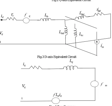
The equivalent qd0 circuits of anLSPMSM with the reference frame fixed in the rotor are shown in Figures 2- 4. The corresponding qd0 voltage and flux linkage equations for the motor are summarized as in equations (1) - (11).
The qd0 Voltage equations are as presented in equations (1) - (5).
d r q q s q
r
i
p
V
(1)q r d d s
d
r
i
p
V
(2)0 0 0
r
i
p
V
s
(3)' ' '
0
r
kdi
kd
p
kd (4)' ' '
0
r
kqi
kq
p
kq (5)where
V
q,
V
dare q- and d-axis stator voltages while' '
,
,
,
d q dq
and
are flux linkages of stator and rotor. The dand q axis stator and rotor currents are expressedas
i
d,
i
q,
i
d'and
i
q' . While stator resistance is given byr
s;
' '
kq kd
and
r
r
are the rotor resistances.
ris the mechanical speed of the rotor. The flux linkage equations are defined as in equations (6) – (11)' kq mq q q
q
L
i
L
i
(6)' ' m kd md d d
d
L
i
L
i
(7)' '
m md m
L
i
(8)0 0
L
lsi
(9)' ' ' kq kqkq q mq
kq
L
i
L
i
(10)' ' ' ' m md kd kdkd d md
kd
L
i
L
i
L
i
(11)The electromagnetic torque is given by equation (12).
d q q d
e
i
i
P
T
2
2
3
(12)
Substituting equations (6) and (7) into equation (12) yields,
d q
d q
md kd q mq kq d
md m qe
L
i
i
P
i
i
L
i
i
L
P
i
i
L
L
P
T
' ' '2
2
3
2
2
3
2
2
3
(13)In equation (13), the developed electromagnetic torque comprises three components,i.e. a reluctance component, which is negative when
L
d
L
q; an induction component which is an asynchronous torque; and an excitation component from the field of the permanent magnet.The mechanical torque equation is given by equation (14).
dt
d
J
B
T
T
m L m
(14)where
L
T
= the load torqueB
= viscous frictions coefficient J = inertia of the shaft at the load system The rotor mechanical speed is expressed as(15)
dt
J
B
T
T
e L mm
(16)
2.3 Equivalent dq0 Circuits
Fig.2 Q-axis Equivalent Circuit
Fig.3 D-axis Equivalent Circuit
Fig. 4 Zero Sequence r
r
p
+ -
s
r
'lkq
L
r
lkq'd
mq
L
ls
L
q
V
q
i
' m
i
' lkd
L
' lkd
r
rc
L
ls
L
md
L
-q
d
V
d
i
r
sq
L
q
i
q
V
md d
i
L
III. SIMULATION RESULTS AND ANALYSIS
Computer-based analysis of electrical machines requires that appropriate measures are made towards the proper selection of a simulation tool. The complex models of some electrical machines need computing tools capable of performing dynamic simulations with greater efficiency and accuracy. SIMULINK has the advantages of being capable of complex dynamic simulations, graphical environment with visual real time programming and broad selection of toolboxes [7]. Hence, this section presents simulation results of all the machine models developed in this paper.
With the Simulink model developed in Figure 5, the model is debugged and simulated. The simulation is set to run for 10 computer seconds. The rated load torque of 15 N-m was set to be applied at 5 seconds when the machine has attained full speed and all the transients had died down. The parameters of 2.8 kW IPM motor are as shown in Table 1.
Fig.6 Rotor Speed Rotor
Speed, r.p.m
Fig.7 Stator Currents
Fig.8 Torque/Speed characteristics
Fig.9 Electromagnetic Torque
A
i
as,
A
i
bs,
A
i
cs,
Time, Sec
Torque, N-m
Speed,r.p.m.
Ele ctr om agn etic Tor que , N-m
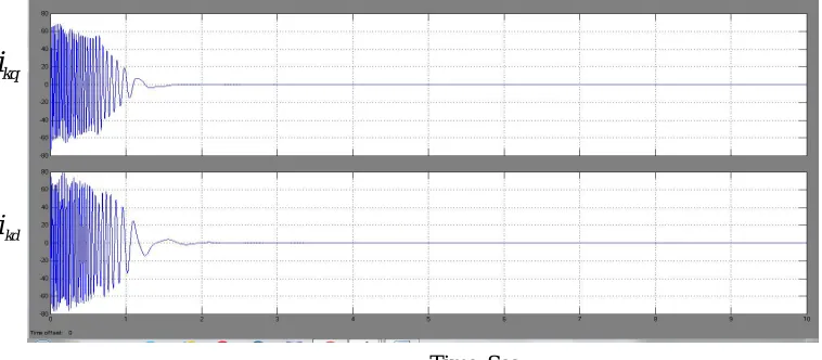
Fig.10 Damper Currents
Fig. 11 Rotor Currents
IV. DISCUSSION
Fig.6 indicates the run-up speed of the motor, which indicates that the rotor starts from rest at no load and accelerates to synchronous speed. It is also important to note that prior to the attainment of full synchronous speed, a little transient was observed. This is the expected speed of a 4-pole, 50 Hz motor operating under line-start mode.
The three-phase stator currents
i
as,
i
bsand
i
csare plotted against time in Fig.7. The currents are observed to be visibly high at starting but settle down to the rated no load current.Fig.8 is a plot of torque vs speed for the acceleration of a 2.8 kW LSIPM motor. This illustrates what happens as the motor tries to pull into step. The looping spiral around synchronous speed provides a vivid depiction of the searching of the motor to lock-in step with the source. It is also observed that the starting procedure is very similar to that of induction motor as the machine derives its line-starting ability from the rotor damper cages.
The torque versus time plot is shown in Fig.9. After the initial transients that characterized the motor, the torque naturally settled to a zero value.
kq
i
kd
i
Time, Sec
A
i
d,
A
i
q,
A
i
0,
In Fig.10, which is the representation of damper currents,
i
kdi
kq, it is observed that the currents are zero at steady state except during load changes. Starting transient is also observed due to the effect of inertia as the rotor accelerates from rest to steady state.The rotor currents
i
o',
i
q'and
i
d' are plotted together as in Fig.11. Very high but transient values were noticed at the onset of the simulation.V. CONCLUSION
The performance analysis of a line start interior permanent magnet synchronous motor has been investigated in this paper. The analysis followed the derivation of a mathematical model and the simplified d-q model to provide insight into the dynamic performance of a LSPMSM through model simulation using an embedded MATLAB function. The paper investigated the start-up and synchronization performance of the LSPMSM for load variations.Simulation results showed that the LSPMSM has adequate starting characteristics in the asynchronous operating region and the torque capability and efficiency in the motor’s synchronous operating region. Further model simulation results reveal that the motor runs in constant speed irrespective of the change in loads during its operation.
REFERENCES
[1] Ong, C. M. Dynamic Simulation of Electric Machinery using MATLAB/Simulink, Prentice Hall, 1998.
[2] Stoia, D., Antonaie, M., Ilea, D. and Carnat, M. Design of Line Start PM Motors with HighPower factor,Powereng, Portuga, 342 – 346, 2007. [3] Arash, H. I. and Sadegh, V. Effect of Magnetizing Inductance on Startup and synchronization of Line-start Permanent Magnet Synchronous Motors. IEEE Transactions on Magnetics, Vol. 47, No. 4, pp. 823 - 829, 2011.
[4] Popescu, M., Miller, T. J. E., Mcgilp, M., Strappazzon, G., Trivillin, N. and Santarossa, R. Line-Start Permanent Magnet Motor: Single – phase StartingPerformance Analysis. IEEE Transactions on Industry Applications, Vol. 39, No. 4, pp. 1021 – 1030, 2003. [5] Amidreza, B. and Alireza, S. Line Start Permanent Magnet Synchronous Motor Performance and Design: a Review. Journal of World Electrical Engineering and Technology, Vol. 4, Issue 2, pp. 58- 66, 2015.
[6] Ogbuka, C. U., Nwosu, C. M. and Agu, M. U. Performance Comparison of Line-Start Permanent Magnet Synchronous Motors with Interior and Surface Rotor Magnets.Indian Journal of Science and Technology, Vol. 9, Issue 4, pp. 1 - 7, 2016.