Internet of Things (IOT) based
Reconfigurable and Scalable Wireless Sensor
Network (WSN)
Ashwin Pai1, Lakshmi Nair2, Abhay Kshirsagar3
U.G. Student, Department of Electronics Engineering, VESIT, Mumbai, Maharashtra, India1, 2
Associate Professor, Department of Electronics Engineering, VESIT, Mumbai, Maharashtra, India 3
ABSTRACT: IoT based Reconfigurable and Scalable WSN is a wireless sensor network which aims to monitor the data recorded by the sensors over the internet. It provides real time feedback to the observer and also alerts them when the sensor values are out of range. It supports plug and play feature making it reconfigurable and based on the values of the sensor it will change the transmission rate making it scalable. In addition, the transmission of data will be security encrypted. IoT based WSN will definitely be used in all the domains in the future right from Manufacturing to Remote Health Monitoring. In this paper, we are going to discuss creation of the system, the advantages of such a system in addition to the ease of implementing it.
KEYWORDS: IoT, WSN, Reconfigurable, Scalable, Security Encrypted.
I. INTRODUCTION
II. BLOCKDIAGRAM
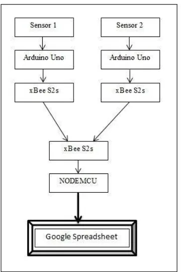
As shown in Figure 1, block diagram of IoT based WSN consists of the following components:
1. Sensor
In our project we have used two sensors.
A. Temperature Sensor
We have used a LM35 for measuring the temperature. It is a precise temperature sensor with its output directly proportional to the temperature in degree centigrade. The temperature can be measured more accurately as the sensor circuitry is sealed and it possesses low self-heating.
B. Heart Beat Sensor
The heart beat sensor is used to detect the heart rate of the person. We have used KY-039 module. This module uses bright infrared (IR) LED and a phototransistor to detect the pulse of the finger.The light side of the finger is kept on the LED while the other side of the finger is kept on the phototransistor. The phototransistor is used to obtain the flux emitted. When the finger is placed, the resistance of the photo transistor will change. The most important part is to keep the shield stray light away from the phototransistor. For home lighting that is particularly important because the lights at home mostly based 50HZ or 60HZ fluctuate, so faint heartbeat will add considerable noise. We can count the number of pulses and detect the heart rate.
2. Arduino Uno
Arduino Uno is used as a controller in this project. The main function of the arduino is to receive the analog sensor values, process it according to the sensor specification and then transmit it serially to the xBee S2C. We can use any other controller in place of Arduino. We have used Arduino because of its simplicity and ease of operation.
3. xBee S2C
The xBee S2C is used to transmit the data wirelessly. It has an advantage of low power consumption and it provides reliable, self-configurable and self-healing networks. xBee S2C also provides security encryption making the transmission of data safe.
4. NodeMCU Development Kit 1.0
NodeMCU is an open source IoT platform.It includes firmware which runs on the ESP8266 Wi-Fi SoC, and hardware which is based on the ESP-12 module. To sum it up we can say that a NodeMCU Dev Board is a combination of Arduino and ESP8266.NODEMCU can be easily programmed using the Arduino IDE. The main task of NodeMCU in our project is to connect to the Wi-Fi and transmit the data to a Google Spreadsheet.
III.CREATINGTHESYSTEM
The sensor node is very simple to build. It consists of an Arduino Uno, Xbee Shield, xBee S2C module and the sensor. The Xbee Shield is mounted on top of the arduino Uno and it has a provision to attach the xBee module [2]. The sensor pins are connected to the arduino via the Xbee Shield. The sensor output pin is connected to the analog input of arduino. The arduino will process the sensor input and convert it to digital output. The system can be created by following the given steps:
1. Creating the xBee network
To program the xBee, we use XCTU Software. Using this we create a xBee network by assigning a common PAN ID to all the xBee modules. Then define a unique address for each of the xBee’s and we encrypt the data using 128 bit encryption[3].
2. Programming the Arduino
We can program the Arduino according to the sensor we used. We require Arduino IDE software in order to program the Arduino. The arduino has 8 analog pins. We can connect the sensor to any of these pins and choose that pin as input pin in the program.
3. Creating a Google Spreadsheet
We first create a Google Spreadsheet and then write a script for it. The script is mainly written in order to enter the data in the proper format along with the time stamp in the spreadsheet [4].
4. Coding the NodeMCU
The NodeMCU is coded using Arduino IDE. The NodeMCU is programmed to connect to the Wi-Fi and in order to assign the delay according to the pre decided range conditions.
Thus we can see that in four easy steps the IoT based reconfigurable and Scalable WSN is created.
IV.WORKING
1. The temperature sensor senses the body temperature of the patient and sends the data to the Arduino Uno. The data is processed here and the temperature is calculated. This value is then sent to the xBee module via the serial pins. The xBee module transmits the data after encryption.
2. When the fingertip is placed in between the heart beat sensor, the pulse gets detected and it is recorded by the Arduino Uno. It counts the pulses for a short period of time and calculates the pulse rate. After it is calculated, it transmits the value to the xBee module via the serial pins. The xBee module on receiving the data transmits it wirelessly after encryption.
4. The data uploaded on the Google Spreadsheet can be accessed from any part of the world, but to access the data the owner has to grant permission. Thus making the readings secure from public access.
Figure 2: Sensor node 1 Figure 3: Sensor Node 2
Figure 2 shows the first sensor node. We have attached a temperature sensor LM35 to analog pin 1 of the Arduino. Figure 3 shows the second sensor node. Over here we have attached a heart beat sensor KY039 to the analog pin 2 of the Arduino.
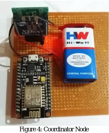
Figure 4: Coordinator Node
V. RESULTS
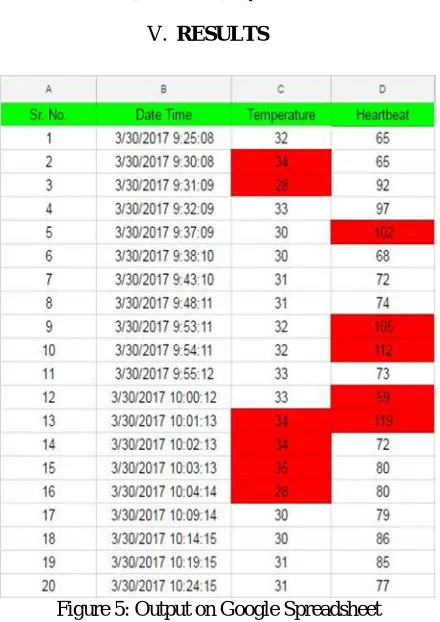
Figure 5: Output on Google Spreadsheet
Figure 5 shows us the data that is received on the Google Spreadsheet. We can clearly see that out of range values are highlighted in red which makes it easy for us to identify them. The figure also helps us understand the time delay i.e. if the data is within the range the next reading is recorded after an interval of 5 minutes, but if the values are out of range, the next reading is taken after a delay of 1 minute.
Figure 5: Temperature vs. Time Graph Figure 6: Heartbeat vs. Time Graph
VI.ADVANTAGES
The Sensor Network will be easy and convenient to use since there will be no wired connections. A wired system consists of a lot of wiring, a small cut in any of the wires means the system is down. It is difficult to add new sensor nodes in a wired network as it will involve reconfiguration of the system. The wired network cannot go through partitions like walls. This is the main advantage of a Wireless Sensor Network.
The system would be very useful for remote monitoring. This would allow the concerned people to view the data from any location. This is possible since the data is being sent and stored in the Google Spreadsheet.
Thedata transmissionis secured with the help of encryption, thus making the system private and protected. It is also made sure that the data can only be accessed by authorized parties which in this case would be the hospital, the doctors and the patient. Nobody else would be able to access this data.
The control unit would be checking the parameter to see whether the data is in the normal range. If it is not in the normal range then it will send the data with minimum delay and this will be alerted on the Spreadsheet.
VII. APPLICATIONS
The system has been designed to be an application oriented system. We can build many applications by just changing the sensor used. Some of the applications that are possible are:-
Health Monitoring System
Weather Monitoring System
Agricultural Monitoring System
Pollution Monitoring System
Forest Fire Detection
River Water Quality Detection
VIII. CONCLUSIONANDFUTURESCOPE
The sensor network transmits the values from the sensor node after encrypting it to the coordinator node using IEEE 802.15.4 standard. The coordinator node on checking the sensor value for the range condition varies the time interval accordingly and sends the data over the internet to a Google spreadsheet. The out of range values are highlighted on the spreadsheet. The Wireless Sensor Network created can be used for a lot of applications. If we change the heart rate sensor with a humidity sensor, then the system becomes a Weather Monitoring System.
The future scope of the project lies in creating an online database for the system using cloud. The data can then be displayed on mobile applications or web-pages with password protection. The sensor nodes can be reduced to the size of a small pen drive by using Wireless MCU’s like CC2531. This will make it very convenient for the user. We can also use sleep function in arduino and xBee to make it a low power system.
REFERENCES
[1] Feng Xia, Laurence T. Yang, Lizhe Wang and Alexey Vinel, “Internet of Things”, International Journal of Communication Systems, Vol.25, pp.1101-1102, 2012
[2] Scott C, “Arduino UNO - XBee Setup”, 2012, Retrieved from http://arduinobasics.blogspot.in/2012/10/arduinobasics-arduino-uno-xbee-setup.html
[3] Robert Faludi, “Building Wireless Sensor Networks”, December 2010