Design of Zigbee Based Wireless Sensor Network
(WSN) and Human Machine Interface (HMI) for
Industrial, Utility Air Supply Section
Eng. Chinmaya Panda 1, Prof. R N Patil 2
M.E Student, Department of Electronics & Telecommunication Engineering, Marathwada Institute of Technology,
Aurangabad, Maharashtra, India1
Associate Professor, Department of Electronics & Telecommunication Engineering, Marathwada Institute of
Technology, Aurangabad, Maharashtra, India2
ABSTRACT: When we will listen about the word Core Industries, then obviously we get a rough figure of very harsh and inhuman conditions. So to accomplish all required job in these inhuman conditions we require Machines, with some control system or you can think of “Intelligence to machines”. As per present industrial automation developments the control system is electronic based and centrally located, where as all necessary actuating and measuring equipments are nearer to machines. That is the reason why huge numbers of cables need to be laid between centralized controllers and machineries, along with a lot of very sensitive, costly and low EMI cables used for measuring devices. Even though this much of hard work imparted still the trivial systems are not flexible, for rapid deployment of new instruments or necessary changes in existing control systems. Also the system is unsafe due to frequent movement of materials by transporting vehicles and environmental effects. Probably that is the reason why industries are interested for this new technology of Wireless Sensor Network. Most probably in near future, WSN technologies might be complete replacement of wired system.
In this paper I have briefly explained basic requirements and procedure for designing WSN. As this publication is one part of my project work, so you will find a detailed analysis, design aspects and design issues during creating a NODE of WSN and inter linking hardware and software. This paper has started with explanations from hardware and software selection process then the explanations regarding system design and issues. You can save your prototyping time as explanations on issues I have faced during prototype design have been mentioned. Finally this paper concluded with future developments and scope.
KEYWORDS: IWSN, WSN, Zigbee, Xbee, HMI, SCADA, VB.NET, Arduino DUE, ARM, Utility Equipment, Air Compressor, Air Dryer, Vacuum Pump, Cooling Tower
I. INTRODUCTION
This Paper is completely focused on Core Industries like Aluminum, Steel, Power, Glass, Pharma and Plastic manufacturing companies. An Ideal core industry can be categorized in to several regions. Final product or base product manufacturing, processing and packaging comes under Production section. Excluding production other sections are known as Utility or Supporting section for Production. Most required Utility is Energy, inform of Electricity, Fuel, High pressure dry air and high pressure fluids. In manufacturing, production and packaging section most of the instruments, machineries and control systems are industry specific. So our focus is on generalized system.
Sensor Network (WSN) technologies to collect energy data from different energy meters by using wireless technologies.
Most important form of energy is Fuel. In fuel handling section we require to store and distribute Gases like LPG, Propane, NG and some other flammable gases, liquid fuels like furnace oil, diesel, petrol, HSD like fuels. This section has considered as most critical due to presence of flammable gases in environment. Instruments found in these regions are of special kind with flame proof design, generally known as intrinsically safe Instruments. Here also lots of possibility to implement WSN technology.
For actuation of different mechanisms commonly used form of energy is Dry Compressed Air. Air handling system is consists of air compressors, air dryers, air heaters, boilers, Vacuum pumps and air receivers. In these sections of utility highest level of Vibration, Noise and electromagnetic interference exits, due to operation of huge induction devices. Most technologists don’t want to spend more time in these areas, but corporate job and responsibility forces them. SCADA based system are also available for this areas. Implementation of WSN in these areas are most challenging, bust most necessary, due to existence of complex circuit of mechanical piping and high voltage Electricity.
Industries require different type of waters for different uses like RO water for drinking and wash rooms, Soft water for Steel pipe lines and DM water for GI and MS pipe lines with Cathodic protection. In pharmaceutical and food processing industries most pure form of water is used to prepare medicines or food products. For these reasons industries requires raw water storage tanks, over head tank, RO plant, Softener plant, DM plant, ETP Plant, STP plant and storage tanks. Over head tank uses gravitational pressure to supply water for different machineries and in case of emergency water supply. Also Cooling towers are available in so many places to keep Machineries and other plant equipments in cool condition.
In this paper I am going to explain only one section i.e. the air handling system. My final prototype is having other utility areas, which you can find in future publications. I have designed some control system for Air Compressor, Air Dryer, Cooling Tower, Vacuum pump & safety shut down system. Those who are reading this article might be well known about the issues and drawbacks in wired signal transmission. So I am not going to mention all these commonly known factors like cost of cable, cable routing issues, cable tray, cable tray support, damage of cable due to machine movements, Electromagnetic interference, environment and rats so on.
In this paper I have carefully mentioned all required stuffs in a simple way so that the reader’s can understand the concept and if they want to make their hand dirty then probably they can copy my system or can design similar systems with proor permission. I also have explained all detail research and survey activities done by me before finalizing the final design, so that if you like my think process then you are free to adopt and in case of allegations and controversies you can contact me or call me directly.
Warning that you are going to overload your brain, so have some refreshment then start reading next, During this writing I have a big cup of coffee with me.
II. PRIOR WORK
Lot more effort have been taken by different technologists and researchers to give reality to wireless technology. Many engineers had successfully implemented WSN technologies in Home Automation and sort distance communications. Industrial implementations need much more refinement in technology.
Mr. Vara Manthan Kantilal [1], have tried to connect PLC & SCADA based automation system by using wireless connectivity. He had used Allen-Bradley Micrologix 1000 (PLC), RSLogix for PLC programming, KEPServer as database & RSView for SCADA and Tarang F4 Zigbee Module as Wireless Radio. He was able to operate SCADA based switch to change LED status. It was a good initiative to connect Zigbee with PLC.
Mr Amulya & his team [2], had Used different temperature sensors (LM35) and Zigbee RF radio along with AT89S52 processor board for collecting different temperature readings and transmitted data through Zigbee. All temperature readins are visualized in PC by help of visual basic based GUI.
(G-4500, manufactured by ICP DAS). Finally the signal was received by GPRS Router which is connected to PC, where Visual Basic Software is running to visualize energy parameters of different energy meters.
Dr. Raymond S. Wagner of Johnson Space Center, NASA, [6] has published a very good real time implemented paper related to implementation of IEEE 802.15.4 for space flight applications. In his paper he have compared 3 different wireless radio protocols like Zigbee, Wireless HART, ISA100.11a. final prototype was tested by using TI MSP 430 processor and ready to use WSNradio manufactured by Crossbow. He was not happy with the performance of the IEEE 802.15.4 modules performance due to lot more issues like interference with wifi frequency, signal dropping and so on. This paper is very informative and have good explanations of all 3 types of protocols.
Mr. Arther Low [11], had well explained the evolutionary developments in wireless radio technologies and compared technical aspects of 2 wireless protocols like wireless HART and ISA100.11a.
In this paper I have no interest to explain theoretical aspects of Wireless technology. Interested readers can refer [ [6], [7], [11],[12].
III.HARDWARE SELECTION
When I have decided to do WSN based prototype, then my main concern is in the hardware and the microcontroller used in this project. It should be able to work in harsh industrial environment and should be reliable. I also consider that in future the product I am using should not be obsolete, because change in hardware required a new hardware design, which will waste our time. For that reason I had fixed my micro controller architecture as ARM. I am not interested in designing the PCB by using Proteous or eagle like software then follow manual etching process to make a development board. As per my past experience the home made PCBs are not so good in performance and reliability, so I had decided
that I am going to use readily available low cost ARM based most advance development board.
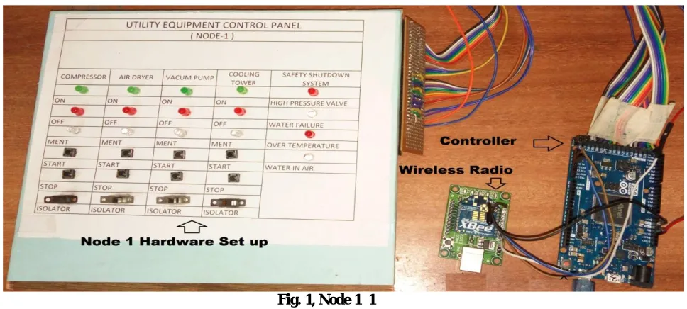
Fig. 1, Node 1 1
This board contains 54 digital input output, 12 PWM IO, 12 Analog IO, 4 UART, 2 DAC, 2 TWI, 1 SPI, 1 JTAG, with ARM Cortex M3 CPU. Most interesting is very low cost board from china worth 1300 rs in India with USB cable and Box. As extra butter on bread even the Software IDE is also Open source and easy to use. Program development time reduced effectively due to Arduino IDE as, maximum of required libraries are included in IDE, so no need to refer microcontroller datasheet to find pin configurations, register details, flag details and become crazy. It’s not necessary for embedded developers to think about the hardware they are using, rather they can use the benefit of software to complete their tasks, and mean time the back ground software will take care of hardware details. I personally thank to Professor Massimo Benzo and other Arduino developers for creating such wonderful pieces of open source hardware and software.
IV.WIRELESS RADIO SELECTION
I have studied different publications before selecting wireless radio. The most critical aspect of selection of wireless module is its cost, availability, compatibility and reliability. These modules are of huge cost, easy to damage, and less frequently available. When we think the real time implementation of wireless technology in industries then we need to think the licensing aspects also. So our wireless radio should use license free band, at India it is 2.4 GHz for IEEE 802 modules. There are 3 most common designs are available of this kind like Wireless HART, ISA100.11a and Zigbee. Zigbee is most popular hardware radio architecture for NET & APP layer. ( I am not going to explain the comparison between these modules and other design aspects of Zigbee. Interested readers can refer relevant references). Again Zigbee has different modules like Xbee s1, s2, s2b, s2c, Pro s2b, Pro s3b so on. Starting from 2mW to 63 mW designs are available, with range from 60 meter to 45Km if we use Xbee Pro s3b with high gain RPSMA dipole antenna. Most interesting thing is the Xbee modules are working in 3.3V DC and my hardware is also of same range, so no need of external voltage conversion ckt. In mean time I am targeting to complete the prototype development with lowest possible budget, so used Xbee S2 2mW module costs 1300 rs see Fig. 1. Obviously its range is less but for project development it’s ok for me. Most interesting fact is that, all available modules of S1, S2, S3 are pin to pin compatible, so no need to change a single wire in final design, if I require a higher range wireless radio. Xbee modules should be programmed before using it. Also we need to set topology. In simple language we can say we need to configure the transmitter and receiver by providing each other’s address. For this reason I have used XCTU NG software to configure these modules. I have configured Node-4 as Zigbee Coordinator AT and Node-1 as Zigbee Router AT, to form a start topology not point to point. TO configure Xbee modules I have used Xbee USB adapter board made in India costs 250 rs.
V. SOFTWARE SELECTION
There are lots of options we have for software delopment like:
Using Java for GUI, HTML, C++, VB, MySQL, MS Access…etc. But finally I find that VB.NET 2015 is easiest software package. This software helps developers in a very innovative way. We have to design the external objects or GUI, then double clicking on each component will create a ready to use program known as sub class. The programmer needs to write the function or action need to be done by the object. Even lots of online tutorials and supports are available, so developing GUI becomes easier and time saving.
Finally I can conclude that I have selected Arduino DUE development board to interface external hardware or machine and wireless radio. Xbee series 2 is used as wireless Radio with Xbee USB adapter board and VB.NET 2015 is used for designing GUI.
VI. SYSTEM DESIGN
machines. In simple way we can define a Node as a hard wired system connected with certain microcontrollers with a wireless radio see fig. 1. In wireless sensor network (WSN) design we assume or design in such a way that each node should be separated or there should not be any wired connection not even power supply. Each node should be portable, battery operated and low power embedded system, which inter connected with real time environments or machineries to gather required information and send the raw or processed information to specific user defined format to remote trans-receivers.
At present I have designed 2 nodes one is for Utility equipment control i.e. Node-1 and other one is Node-4 used to receive other nodes information and send data to connected Computer, where GUI software is running. (Other 2 nodes are not relevant to this paper so better if you ignore these 2 nodes).
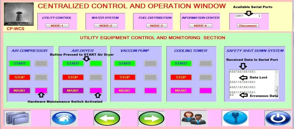
In GUI you will find 3 switches for each machine and 3 indications for status updating. One Switch specifically called as Button is used to start or stop the machine and the corresponding status LED is visible near to that. Third button is for safety. During the time of maintenance the maintenance team should operate concern hardware isolator. In case the machine operator gives start command or due to some communication error if start command provided to machine it will not start.
In GUI option is available to select the serial port to which our wireless radio or the microcontroller development board is connected. Also we can see all receiving data to our serial port so that we can calculate required performance metrics and troubleshoot communication related issues.
In Hardware design I have connected push buttons for Start & Stop operation, 2 position switches for maintenance isolators & LEDs are used to see the status of machine.
Interlock1: If maintenance switch is pressed then there should not be any valid operation by start or stop switch Interlock2: Only once operator have to press the start or stop switch for few seconds. After release of start or stop switch the machine or the controller should retain the status. If machine have started, then it should maintain it’s condition after release of concern button till other button operated. I don’t recommend to use software buttons for maintenance. To avoid safety related issues, we must practice to used hardware isolator during maintenance.
VII. HARDWARE PROGRAMMING
I have made program very simple so that other programmers can understand. New syntaxes are commented so no need to refer huge libraries. Each pin is assigned with easy to remember names, so during program no need to think about pin numbers rather concentrate on pin name which is easy to remember.
const int comp_on_sts = 26; pinMode(comp_on_sts, OUTPUT);
Each LED and Each Button is connected to different DI/O pin of DUE. Pull down resister is connected to each switch so that we will get exact 0 V when switch is pressed and 3.3 V will provide when button is released. As more than 3.3V will damage the controller, so supply to LED and Pull Down circuit of switch are connected with development board power pins. Finally each pin status has been stored in a character array starting with letter ‘A’. Letter ‘A’ is used to recognize the node from where data has received by GUI. (). Received data from GUI is stored in an integer variable (rdata = Serial1.read(); ). This variable is compared with switches so that operators can avail full functionality from hardware and software prospective.
if((digitalRead(comp_ment_sw) == HIGH) || (rdata == '3')) {
digitalWrite(comp_ment_sts, HIGH); a[3]='1';
} else {
digitalWrite(comp_ment_sts, LOW); a[3]='0';
VIII. SOFTWARE DEVELOPMENT
As I am using VB.NET so it’s compulsory that you should have window based system to run the program or to edit it. In GUI program I have used 4 no of Forms but in this paper only form-1 have been explained. Software will accept serial data started with letter ‘A’ & separated by ‘,’ and ends with ‘\n’. This string is stored in a character array and latter used to change concern object properties.
msg = SerialPort1.ReadLine()
If msg.StartsWith("A") Then
node1 = msg.Split(",")
btn7 = node1(1)
In case any button will clicked, then it will send a number or character to Arduino. (Receive value in serial is in form of ASCII so used character to send data and compared with it’s ASCII value in program).
Private Sub Button8_Click(sender As Object, e As EventArgs) Handles Button8.Click
SerialPort1.Close()
send_serial_data("2")
SerialPort1.Open()
End Sub
When form loads all available serial ports will be displayed in a combo box, and latter you need to select required serial port to receive data. In a Ritch text box all receive data even garbage value also visible, so that we can troubleshoot connection or program related issues see Fig. 2.
IX.SIMULATION AND RESULT
Completed prototype has been tested. In this section you will find different test observations and experimental data. We need to select the serial port and press the “Connect” button, after a valid selection, SCADA will start acquiring data from selected Serial Port.
In above SCADA system all Buttons and Indications had been tested along with exact functions in hardware. There are few millisecond delay observed to activate LED after switch press it’s due to delay function in Arduino Programming. Status updating in SCADA takes less than 5 second, these delay is due to Timer Tick operation of VB.NET software and Programmed delay in Arduino.
As per my experimental observations it is true that general purpose Xbee modules (S1,S2 2mW series) are not well capable to trans-receive data if Wireless modules are placed at Out of Site. Maximum time it drops connection if distance is high. Better operation without uninterrupted communication is observed within 100 meter of range.
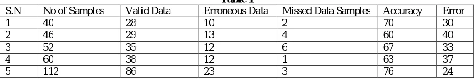
Table 1
S.N No of Samples Valid Data Erroneous Data Missed Data Samples Accuracy Error
1 40 28 10 2 70 30
2 46 29 13 4 60 40
3 52 35 12 6 67 33
4 60 38 12 1 63 37
5 112 86 23 3 76 24
I had conducted 5 experiments, by keeping Xbee modules within 5 meter line of site (Refer Table 1). I should receive an array of data starting with character ‘A’ and followed by 12 bit of data representing status of 12 indicators (A,1,1,1,1,1,1,0,0,0,0,0,0,\n). I had found that accuracy of system is approximately 67%, Erroneous data received is of 23% and Data missed is of 6%. For non critical applications this might be acceptable, but not for industrial continuous process operations. In near future, I am planning to test Xbee Pro with same prototype.
X. FUTURE DEVELOPMENT
In near future I am going to implement Database to store analog values. Received data need to be stored directly in database. GUI should receive data from database rather than from serial buffer. So after implementation we can visualize trends, Historical data points, and other necessary critical alarm logging functions. Few organizations require redundant hardware design. Those machineries should have some provision to be operated, in case there is a complete failure of embedded system. This can be implemented by using extra relay interfacing panel, which can be interlinked with microcontroller development board using optocouplers. For that reason the designer need to take extra effort for hardwired design with option of Auto control & Manual control. Future is endless; Even we can implement client & server side programming to visualize the system from remote locations. VB.Net environment is robust but requires lots of memory and also time consuming. So to speed up the system performance we can design whole system by using C++ or JAVA along with MySQL database support. As we all knows that embedded systems can’t recover from some deadlock conditions and can’t heal itself, so interested researchers can port Real Time operating System like FreeRTOS or uCos, into the microcontrollers.
XI. CONCLUSION
REFERENCES
[1] Vara Manthan Kantilal, Anurag P. Lokhlani, “Zigbee Based Wireless Monitoring and Controlling of automation System using PLC and SCADA”, International Journal of Advanced Research in Electrical, Electronics and Instrumentation Engineering, Vol.-3, Issue-1, January 2014
[2] Amulya Keeli, E.Prudhvi Teja, N. Devi, G. Venkateswarlu, “Wireless SCADA for Industrial Automation”, International Journal of Advanced Research in Electrical, Electronics and Instrumentation Engineering, Vol. 4, Issue 4, April 2015
[3] 3. Hung-Cheng CHEN, Long-Yi CHANG,“Design and Implementation of a ZigBee-Based Wireless Automatic Meter Reading System”, Electrical Review, National Chin-Yi University of Technology, 2012
[4] M.Sujitha, Dr. V. Kannan, “Zigbee Based Real Time Plant Monitoring System Using uC/OSII ”, Journal of Theoretical and Applied Information Technology, Vol. 65 No.1, July 2014
[5] Rajeev Piyare, Seong-ro Lee, “Performance Analysis of Xbee ZB Module Based Wireless Sensor Networks”, International Journal of Scientific & Engineering Research, Volume 4, Issue 4, April-2013
[6] Raymond S Wagner, “Standards-Based Wireless Sensor Networking Protocols for Spaceflight Application”, IEEE Aerospace Conference, March 11 2010.
[7] Miguel Garcia, Diana Bri, Sandra Sendra, Jaime Lloret, “Practical Deployment of Wireless Sensor Networks:a Survey”, International Journal on Advances in Networks and Services, Vol. 3 no 1&2, 2010
[8] Mark Hempstead, Michael J. Lyons, David Brooks and Gu-Yeon Wei, “Survey of Hardware Systems for Wireless Sensor Network”, Journal of Low Power Electronics, Vol. 4, 1-10, 2008
[9] Ananya Chatterjee, Manjusha Pandey, “Practical Applications of Wireless Sensor Network Based On Military, Environmental, Health And Home Applications: A Survey”,International Journal of Scientific & Engineering Research, Vol. 5, Issue 1, January-2014
[10] Arthur Low, “Evolution of Wireless Sensor Networks for Industrial Control”, Technological Innovation Management Review, May 2013 [11] F. L. Lewis, “Wireless Sensor Networks”, Smart Environments: Technologies, Protocols and Applications, Automation and Robotics Research
Institute, University of Texas, Arlington, 2004
[12] Vehbi C. Gungor, Gerhard P. Hancke, “Industrial Wireless Sensor Networks: Challenges, Design Principles and Technological Approach”, IEEE Transactions on ndustrial Electronics, vol.56, no10, pp. 4258–4265, 2009.
[13] Maximilian Riegel, “IEEE 802 Introduction and Overview”, Siemens Moblie, ICM N Advanced Standardization, 11-03-2004
[14] Lamia Charri and Lotfi Kamoun, “Performance Analysis Of IEEE 802.15.4/Zigbee Standard Under Real Time Constraints”, International Journal of Computer Networks & Communications (IJCNC) Vol.3, No.5, Sep 2011
[15] Xie Lu, “Supervisory Control and Data Acquisition System Design for CO2 Enhanced Oil Recovery”, Technical Report No. UCB/EECS-2014-123, Electrical Engineering and Computer Sciences, University of California at Berkeley, May 21, 2014
[16] Sachin Shinde, Rohit Jethmalani, Pankaj Sawant, Adnan Ansari, “SCADA Based Monitoring & Controlling Using Zigbee”, International Journal of Computer Science and Information Technology, pp. 3958-3961, Vol. 3, 2012
[17] Chenxi Ouyang, “Design and Implementation of A Wireless Zigbee Mesh Network ”, Technology and Communication, VASA Yrkeshogskola, University of Applied Science, 2014
[18] Vachirapol Mayalarp, Narisorn Limpaswadpaisarn, Thanachai Poombansao and Somsak Kittipiyakul, “Wireless Mesh Networking With Zigbee”, School of Information, Computer & Communication, SIIT, Thamasat University, Thailand
[19] Xbee/Xbee Pro RF Module, Product Manual v1.xEx-802.15.4 Protocol, IEEE 802.15.4 RF Module by Digi International [20] Creating a Simple Zigbee Communication Network using Xbee, ECE-480, SS13, DT 2
BIOGRAPHY
Chinmaya Panda
His native is nearer to Chilika Lake of Odisha, India. He received his B.Tech degree in Applied Electronics & Instrumentation Engineering from GIET, BPUT University, Odisha in 2011. He is having 5+ yr of rich experience in Electrical & Instrumentation Maintenance department of various Multi National Companies. He have skill in Project commissioning and ISO activities. At present He is a student of M.Eng., in Embedded Systems department at MIT, BAMU, Aurangabad, India. His research interests include Industrial Automation, Instrumentation, Embedded System Design and Machine to Machine Wireless Connectivity.
Prof R. N. Patil