ISSN(Online): 2319-8753 ISSN (Print): 2347-6710
International Journal of Innovative Research in Science,
Engineering and Technology
(An ISO 3297: 2007 Certified Organization)
Website: www.ijirset.com
Vol. 6, Issue 8, August 2017
Efficient Four Layer Group Key Management
Scheme Using Exclusive Basis System (EBS) in
Wireless Sensor Network
Usham Robinchandra Singh1, Sudipta Roy2, H Mamata Devi3
Research Scholar, Department of Computer Science & Engineering, Assam University, Silchar, Assam,India1
Professor
,
Department of Computer Science & Engineering, Assam University, Silchar, Assam, India2Associate Professor, Department of Computer Science,ManipurUniversity, Canchipur, Manipur, India3
ABSTRACT: Wireless sensor networks (WSNs) are deployed in hostile environments in many applications. In a WSN, regular topology patterns such as Square, Hexagonal and Triangle can fully cover the area, provide accurate positioning for abnormal event, and achieve better network performance than random topology using cluster-based techniques. To establish intra-cluster and inter-clusters security with respect to data handling is the prime challenge at this moment. Cluster based key management is one of the good security aspects in wireless sensor network. Sensor nodes of wireless sensor network often use pre-shared secret keys to protect confidential data by encryption. Hence, an efficient key management scheme is necessary which reduces the impact of node capture attacks and consumes less energy. A good key management protocol must pay attention to balance the binary tree structure associated with the network as binary search tree with less height behaves more efficiently. The proposed Efficient Group Key Management Scheme is based on the new routing protocol called efficient four layer key management scheme (EFLKMS) analyses Exclusive Basis System (EBS) for hexagonal topology using AVL tree based on hierarchical WSNs during data transmission towards the Base station. When data transfer occurs towards the base station, the data is made to pass through four phases of encryption for ensuring security in the network.
KEYWORDS: Group Key Management, Cluster Head, Security, Cluster Coordinator, EBS.
I. INTRODUCTION
ISSN(Online): 2319-8753 ISSN (Print): 2347-6710
International Journal of Innovative Research in Science,
Engineering and Technology
(An ISO 3297: 2007 Certified Organization)
Website: www.ijirset.com
Vol. 6, Issue 8, August 2017
aggregation, and sending the collected data to the BS[2]. In our proposed work, final data aggregation is performed by cluster coordinator. By capturing a sensor node, an intruder can become a CH and further propagate attacks such as sinkhole and selective forwarding. This could result in disruption of entire network. Therefore more efficient key management scheme based on the Cluster based network need to be established. It is the Clustering which provide a way of efficient data gathering technique in terms of energy consumption. We have applied cluster based network key management scheme using Exclusion Basis System (EBS). The Exclusion Basis System (EBS)[3] was proposed by Eltoweissy el al. in 2014. The EBS is based on a combinatorial formulation of the group multicast key management problem which provides a general framework for the key management systems. In EBS-based scheme nodes are assigned with several keys from a global key pool. And the group rekeying mechanism is executed from the periodical time, or it is executed when certain number of nodes is compromised. In the group rekeying phase, the temporary keys are created. Therefore, these temporary keys encrypted with all the new group key are sent to the nodes which are not compromised by the intruder.
The paper is organized as follows. Section II summarizes Basic Network model, section III discuss related work. Section IV discusses assumption made on the network entities, section V discusses proposed key management scheme, section VI discuss simulation study, and section VII shows performance evaluation of the proposed system . Finally in Section VIII presents conclusion.
II. BASIC NETWORK MODEL
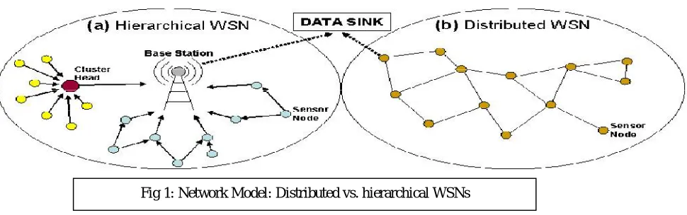
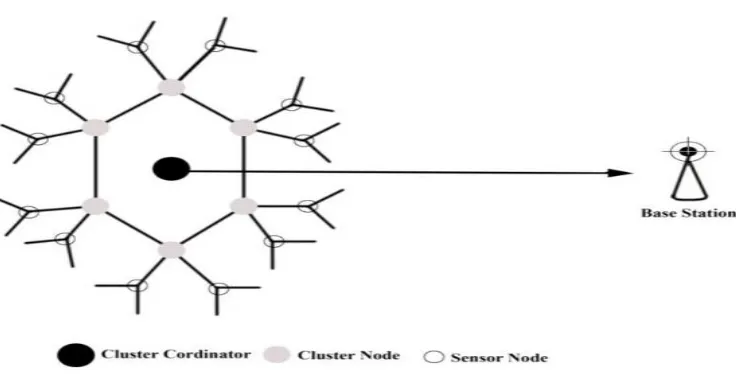
WSNs are very popular as it can provide potentially low cost solutions to a variety of real-world challenges [4]. WSN architecture can generally be organized in two ways: distributed and hierarchal as shown in Figure 1 [5]. A hierarchical WSN has a network hierarchy among the sensor nodes based on their properties such as power and memory. Cluster heads which are used to collect and aggregate local or received data from other end-point sensor nodes and send them to base stations [2]. Data communications in such networks can be: (1) pair-wise (unicast), (2) group-wise (multicast) or (3) network-wise (broadcast). There exist some lightweight key management protocols [6, 7, 8, 9, 10] for WSNs. Cryptography keys in these protocols are transmitted within nodes via messages. So they incur high communication overheads [11, 12]. To see why, let’s consider two communicating nodes in a secure session. A sender node must either send two messages to a receiver node, one for transmitting its symmetric key and another for the message text itself, or just send 1 message containing the text of its message if it knows (has stored) the symmetric keys of all its neighbours. Distributed and hierarchical WSN architectures [5] require different key distribution protocols. In distributed WSNs architecture, sensor nodes use pre-distributed, dynamically generated pair-wise or group wise keys [13, 14, 15, 16]. Efficient key distribution mechanism is required for different type of key usages. Therefore it is necessary for hierarchical WSNs to establish some trusted nodes such as base stations and cluster heads which act as the key server and trust the distributed keys [17, 18, 19, 20] by a secure session establishment. In this paper, only hierarchical architectures are considered. Firstly, a hierarchical architecture, with a single base station and many clusters, is considered. The base station is the network coordinator with which cluster heads in its radio range can communicate. Since sensor nodes have limited radio coverage, the network is clustered in such a way that each cluster head can communicate to the base station in a single hop; ordinary (end-point) nodes within a cluster communicate with their cluster head in a single hop too. Secondly, a distributed architecture without a pre-defined clustering is considered.
ISSN(Online): 2319-8753 ISSN (Print): 2347-6710
International Journal of Innovative Research in Science,
Engineering and Technology
(An ISO 3297: 2007 Certified Organization)
Website: www.ijirset.com
Vol. 6, Issue 8, August 2017
III.RELATED WORK
Different cluster-based approaches have been proposed to handle the challenging issues of WSNs. For secured communication in wireless sensor network, key managements are one of the challenging tasks. Key management plays a significant role for secured communication in wireless sensor networks. Group key is one of the fundamental security mechanisms that are able to provide secure group communication [24]. Nowadays, Clustering is one of the best grouping techniques used in many research areas. Therefore, the cluster based sensors networks behave better in performance and reliability than traditional flat WSNs (FSNs) as [25]. Several key distribution and management schemes have been proposed in WSNs. Cluster based key management techniques called EECBKM [26] are also used for energy efficient key management. EBS key set is used in EECBKM and contains the pair wise keys for intra cluster and inter cluster communication. Results have shown that EECBKM reduces node capture attacks. However fails to
mitigate selective forwarding and wormholeattacks. It is good forsecuring LEACH (Low-Energy Adaptive Clustering
Hierarchy) presented by Heinzelman et al. [27], Zhang et al. proposed RLEACH [28] a secure routing protocol for cluster-based WSNs, using group key management to solve the problem of secure LEACH. Different attack such as sinkhole attacks, selective forwarding can be resisted by using improve random pair-wise key management scheme.
Otherwise RLEACH fails against node capture attack. Jolly et al. proposed low-energy key management protocol LEKM [29]. Further, LEKM used group keys to secure the communication between two cluster heads. In this once the cluster head is capture; all the keys stored in sensor nodes within a cluster are compromised. Zhang and al [30] focus on reducing storage cost of sensor nodes and the communication overhead and propose a cluster-based group key management scheme for WSNs, they employ the threshold cryptography [31,32] and to solve the node isolation problem. The weakness of this scheme is that the communication security within a cluster is affected, once a CH is captured. This scheme also doesn’t provide secure communication between the sink node and cluster heads. Two layered dynamic key management (TDKM) approach for cluster-based WSN (CWSN) was proposed by I.-H.Chuang, W.-T.Su,C.-Y. Wu,et al,[33]. In order to show efficiency, TDKM was used to compare with other key management protocols. Key generation overhead, secured data transmission overhead and network security in CWSN are analyzed by finding the relationship between the number of groups and system performance. An energy-efficient distributed deterministic key management scheme (EDDK) was proposed by X.Zhang, J.He, and Q.Wei [34]. In this scheme, Secure and less communication overhead are well established with the help pairwise keys and cluster keys. They also made use of elliptic curve digital signature algorithm in EDDK, which provided the support for the establishment of pairwise keys and local cluster keys under the node mobility scenario.
IV.ASSUMPTION ON THE NETWORK ENTITIES
The area of key management is one of the good security aspects that provide a mechanism for secured communication in cluster based wireless sensor network. Initially, clusters are formed in the network and the CHs are selected based on the energy cost, coverage and processing capacity. Again, it is assumed that the cluster coordinator (CC) takes the role to collect full information from the CH to enhance rate of data transfer as well as full proof four phase data transfer to base station. Further, CHs are responsible for relaying of messages from ordinary nodes to the Cluster head and then
ISSN(Online): 2319-8753 ISSN (Print): 2347-6710
International Journal of Innovative Research in Science,
Engineering and Technology
(An ISO 3297: 2007 Certified Organization)
Website: www.ijirset.com
Vol. 6, Issue 8, August 2017
CC to BS. Energy efficient key management is depending upon the efficient network arrangement, routing protocol, special distribution of sensor nodes, cluster node and coordinator cluster nodes. Accordingly, designing key management protocols that can securely distribute secret keys among sensor nodes become an important issue for WSNs. Traditionally, the sensor nodes always report their sensing data back to a remote processing center called as the BS in a client-server model [37][38] where the nodes would quickly run out of their energies, and thus substantially shorten the network lifetime. This problem has led to the development of hexagonal topology using AVL tree based on hierarchical WSNs [36]. Many cluster-based wireless sensor network routing protocols have been proposed by the researchers. However, most of them did not consider the communication protection, which is important to ensure the network security and are vulnerable to a number of security threats [39]. Attacks involving CHs are the most damaging. Hence, it is essential to establish encryption keys among sensor nodes, thus restricting the security impact of a node to be compromised [40]. Zhang and Varadharajan [41] presented different key management techniques for different types of network architecture.
In order to implement the proposed efficient four layer key management (EFLKMS), the following assumptions are considered:
1. The base station has more computational and energy power compared to sensors. 2. Only one node called cluster coordinator is able to communicate with the base station. 3. The base station has a pair of keys (private and public key).
4. Cluster coordinator is taken at the center of the hexagonal AVL network model. 5. Cluster coordinator has same distance with all the Cluster head.
6. Each sensor is capable to use:
a. Asymmetric Cryptography: To provide authentication of the base station.
b. Symmetric Cryptography: To ensure the confidentiality of traffic across the network. 7. MAC (message authentication code) is used to ensure data integrity.
8. Each sensor has the capacity to save at least the public key of the base station and one or more symmetric keys used for data encryption.
V. PROPOSED KEY MANAGEMENT SCHEME
1. Cluster head selection
As soon as nodes of wireless sensor network are deployed in the physical environment, they first report to the base station about their actual physical locations and then the network starts to select cluster heads. In the cluster head selection algorithm, each node decides if it is capable of serving as cluster head based on the three selection criteria: (i) Energy cost, (ii) coverage and (iii) processing capacity. Coverage is based on neighbor count of each node. The highest neighbor count and highest residual energy node is selected as cluster head as shown the fig 2. Further, the cluster formation process can lead unfair energy consumption, if the CHs are only elected on the basis of a single objective metric [35]. The clustering approach is used in the proposed network where each vertex represents a cluster head nodes. The network is divided into BS, CC, CHs and member nodes (MNs). BS is powerful and has information of the total network. Each cluster has one CH with limited MBs. In our proposed work, WSN is viewed as a Hexagonal model [36]. The network area is considered as a hexagonal shape and divided into triangle shaped six regions. Each region acts as a cluster that contains sensor nodes. The division is guided by equation (1) and six different colours are used to indicate six regions.
Where (x1, y1), (x2, y2), (x3, y3) are three coordinates of the triangle.
Cluster head for each cluster is selected amongst the nodes that are the closest to the center of a cluster area.
2 2 1 * 3 1 3 * 2 3 2 *1 y y x y y x y y
x
ISSN(Online): 2319-8753 ISSN (Print): 2347-6710
International Journal of Innovative Research in Science,
Engineering and Technology
(An ISO 3297: 2007 Certified Organization)
Website: www.ijirset.com
Vol. 6, Issue 8, August 2017
2. EBS(Exclusion Basis System) Subset Construction
An EBS is a collection of subsets of the set of members. Each subset corresponds to a key and the elements of a subset are the nodes that have that key. An EBS of dimension (N, K, M) represents a situation in a secure group where there are N members numbered 1 through N, and where a key server holds a distinct key for each subset. If subset Ai is in the
EBS, then the key Ki is known by each of the members whose number appears in the subset Ai. Furthermore, for each t
∈ [1, N] there are M elements in the EMS whose union is [1, N] – {t}. This means that the key server can evict any
member t, re-key, and let all remaining members know he replacement keys for the K keys they are entitled to know. This is done by multicasting M messages encrypted by the keys corresponding to the M elements whose union is [1, N] – {t}. Each new key is encrypted by its predecessor in order to limit decipherability only to the appropriate members. To construct subsets of the EBS, a canonical enumeration method is used: consider all possible ways of forming subsets of K objects from a set of K + M objects. For the sequence of bit strings in Canonical(K, M) we form a matrix A, where K and M are understood, and whose C(K + M, K) columns are the successive bit strings of K+M length, each with K ones. “A” is called the canonical matrix for EBS (N, K, M). In this protocol, when the base station constructs EBS (N, K, M) model, the parameters N, K, and M can be raised in value such that more management keys are generated. This way when new nodes are admitted to the clusters, the spare keys can be used directly instead of generating new keys.
For example, the canonical matrix A for EBS (8, 3, 2) contains the enumeration of all C(5, 3) ways to form a subset of 3 keys from 5 keys, as shown in Table 1.
TABLE 1. ENUMERATION MATRIX FOR EBS (8,3,2)
M1 M2 M3 M4 M5 M6 M7 M8 M9 M10
T1 0 0 0 0 1 1 1 1 1 1
T2 0 1 1 1 0 0 0 1 1 1
T3 1 0 1 1 0 1 1 0 0 1
T4 1 1 0 1 1 0 1 0 1 0
T5 1 1 1 0 1 1 0 1 0 0
ISSN(Online): 2319-8753 ISSN (Print): 2347-6710
International Journal of Innovative Research in Science,
Engineering and Technology
(An ISO 3297: 2007 Certified Organization)
Website: www.ijirset.com
Vol. 6, Issue 8, August 2017
Each row of the table (matrix A) corresponds to a subset Ti, where an entry 1 in the row means that the subset contains the corresponding node. As N = 8 thus M9 and M10 are useless. Therefore, in Table 1, T1 = [5, 6, 7, 8], T2 = [2, 3, 4, 8], T3 = [1, 3, 4, 6, 7], T4 = [1, 2, 4, 5, 7], and T5 = [1, 2, 3, 5, 6, 8] and the following are interpreted easily:
[1,8] – [1] = T1 U T2, [1,8] – [2] = T1 U T3, [1,8] – [3] = T1 U T4, …
Therefore, when any node exits from the network, only two subsets of nodes need to send messages to update their keys.
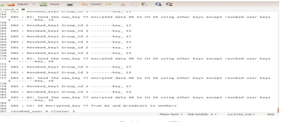
When any user is revoked from the network that time new key is generated to hide the information from revoked user in the network. That key encrypted by BS and send to CH using other group keys except revoked user combination. Then CH broadcast the information to Cluster members. EBS key construction is shown in the figure 3. Each group have corresponding key. The verification (authentication) of any sensor node of particular cluster is done by respective CH. Verification of CC will be done by BS.
Each node knows its immediate neighbors. If a certain attack occurs on the network, BS will alert to network, especially to particular CC, which in turn carries verification for that CH and doesn’t allow it to enter the network. Thus, network will be secured.
3. Architecture:
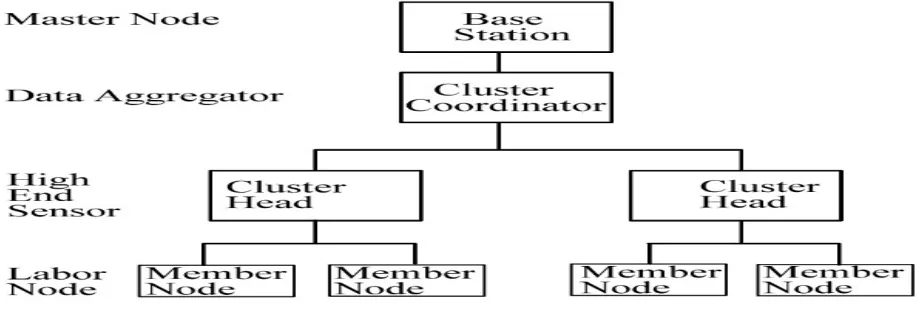
The four layered clustered architecture comprises of Base station at the top level, Cluster coordinator at the second level, cluster head at the third level and low end sensor nodes at the bottom level as shown in figure 4. Grouping of sensor nodes into clusters hierarchically is a method to achieve energy efficiency. Routing is also an important factor that affects wireless sensor networks [42.43]. This architecture highlights the efficient four layered key management (EFLKMS) protocol to achieve secure data delivery based on clustering mechanism. In this protocol, Cluster
coordinator plays an important role among the member nodes by using cluster head by providing secure
communication as well as reliability. A limited energy resource of the sensor nodes is one of the most restrictive factors on the lifetime of wireless sensor network. The main advantage of a multi-layered clustered architecture [44] is that the number of keys loaded in each sensor nodes will be appreciably less compared to distributed sensor networks. It is fact that the hierarchical architecture enhances the scalability of the system. Such kind of architecture provides Division of Labor system where in each node is loaded with optimal work it can perform [45]. Thus, hierarchical clustered
ISSN(Online): 2319-8753 ISSN (Print): 2347-6710
International Journal of Innovative Research in Science,
Engineering and Technology
(An ISO 3297: 2007 Certified Organization)
Website: www.ijirset.com
Vol. 6, Issue 8, August 2017
architecture [46] gives a clear idea of what type of nodes to be used at different levels. In the topology-oriented (Tree or Hierarchy based) group key management frameworks, the group nodes are virtually organized into hierarchical or tree topological structure. In fact, the topology oriented methods put emphasis on improving key computation, message overhead and memory to store keys. However, these methods suffer from frequent topology changes due to node mobility or join or leave operations. 100% connectivity at low power consumption is a main objective in WSN. Maximum transmission power is needed to achieve maximum communication range and thus the range of communication is traded-off with energy consumption. Typically, WSN nodes are expected to work efficiently at low power consumption. In fact, communication range is cut down if power consumption is decreased. Transmission power of communication [47] is ignored if any nodes try to communicate with other nodes without any nodes intervention. . The main advantage of this is the security which is 100%, further; the data received is a primary data. Also there is minimal possibility of data loss. Due to high energy consumption, it is still not welcome in WSN. Here for 100% connectivity all the nodes should be in the communication range of other nodes, this limits the network coverage.
Fig 4: Layered Cluster architecture in WSN
ISSN(Online): 2319-8753 ISSN (Print): 2347-6710
International Journal of Innovative Research in Science,
Engineering and Technology
(An ISO 3297: 2007 Certified Organization)
Website: www.ijirset.com
Vol. 6, Issue 8, August 2017
4. Our proposed protocol
The proposed scheme considers a hierarchical cluster structure of sensor network [36] as illustrated in Fig. 5. The proposed routing protocol called efficient four layer key management protocol (EFLKMS) forecast consumption of less energy during key management process. There are four types of keys in this new routing protocol that is shared key, cluster head key, cluster coordinator key and pairwise key. This protocol is better than EECBKM in terms of storage overhead, computation time, packet transfer, total residual energy, throughout and control overhead.
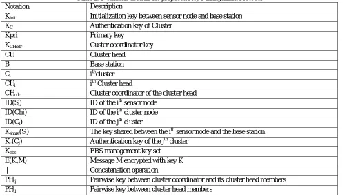
Table 2: Notations used in the proposed Key Management Protocol
Notation Description
Kinit Initialization key between sensor node and base station
KC Authentication key of Cluster
Kpri Primary key
KCHcdr Custer coordinator key
CH Cluster head
B Base station
Ci ithcluster
CHi ith Cluster head
CHcdr Cluster coordinator of the cluster head
ID(Si) ID of the ith sensor node
ID(Chi) ID of the ith cluster node
ID(Ci) ID of the jth cluster
Kshare(Si) The key shared between the ith sensor node and the base station
Kc(Cj) Authentication key of the jth cluster
Kebs EBS management key set
E(K,M) Message M encrypted with key K
|| Concatenation operation
PHij Pairwise key between cluster coordinator and its cluster head members
PHii Pairwise key between cluster head members
Therefore EFLKMS involves these following phases: 1. Initialization phase
2. Pair wise establishment
3. Intra cluster pair wise key management
ISSN(Online): 2319-8753 ISSN (Print): 2347-6710
International Journal of Innovative Research in Science,
Engineering and Technology
(An ISO 3297: 2007 Certified Organization)
Website: www.ijirset.com
Vol. 6, Issue 8, August 2017
Fig 5: Hierarchical Hexagonal model
a. Network Initialization
The sensor network layer is divided into different clusters. Each cluster has a CH which coordinates all SNs in the cluster. A SN can communicate with other SNs in the same cluster and also the CH. All CHs of all clusters can communicate with each other and cluster coordinator is responsible to communicate with the BS. The BS is the first layer which controls the network and also helps in connecting WSN to external networks like Internet. The second layer is the CC layer. CC coordinates all other CHs in terms of data transfer and other operations. The third layer is the CH to collect data from the sensor nodes (SNs). Four layers is Sensor nodes that collect data from the environment. In the first phase, source node collect data from the environment to communicate to the base station. In the second phase, cluster member to cluster head encryption and decryption, in the third phase, encryption and decryption between the cluster head and cluster coordinator and in the last phase data encryption and decryption between cluster coordinator and base station based on exclusive base system. CH consumes more energy due to its heavy responsibilities. To overcome this, CC is introduced to take overall responsible to reduce energy consumption by each CH. The scheme can balance energy consumption by rotating CHs randomly and then assigning jobs to CC. The notations used are presented in Table 2. Before the WSN is actually deployed, each node is given a random number for identification and also a secret key is shared with BS and the rest of the process is as follows. During the formation of a cluster, initially a CH is selected based on eligibility criteria such as energy cost, coverage and processing capacity. CC is proposed as the main coordinator for all CHs. After the CC selection, the information about all the members of the cluster and all cluster heads are sent to the sink by the CC. The base station then provides the CC key, the cluster head key and the EBS key set required for the communication between the nodes. These keys are distributed to the nodes by the CC prior to communication. After the key distribution, secure channel is established between the nodes and the CH. After nodes are deployed to their physical environment, they first report the BS through CC about their physical locations Like the CH selection algorithm, each CH nodes decide if it is capable of serving as a CC. If so, the CHcdr
broadcasts a Hellow packet. The packet must be authenticated and for the authentication process, the encryption mechanism is carried on.
CHcdr
E (KCHcdr,Hellow)
broadcast
Thus for the first time CC formation process, the initial Cluster Coordinator key KCHcdr is used to encrypt the Hellow
packet.
ISSN(Online): 2319-8753 ISSN (Print): 2347-6710
International Journal of Innovative Research in Science,
Engineering and Technology
(An ISO 3297: 2007 Certified Organization)
Website: www.ijirset.com
Vol. 6, Issue 8, August 2017
Chi
E(KCHcdr ,ID(CHi) || Ack)
CHcdr
Finally, the CC assigns IDs to all the CH nodes that intend to join the CC and sends the information to the BS. The BS constructs EBS structure for the CC, assigns the cluster coordinator ID and generates the cluster coordinator key and associated management key.
According to the EBS structure the BS uses the shared main key K share to encrypt data exchange with the CC and CH
nodes within the one particular cluster. All encrypted data are sent to the cluster coordinator. The CC keeps the segment of the data that is intended for it and passes other parts of the data to other cluster node. Upon the completion, all cluster nodes delete Keyinit from the memory. The initial clustering is then finished and the entire logical structure of
the WSN is saved on the BS.
E (Kshare (CHcdr ), ID (CHi) || ID(Sm)....)
CHcdr B
The BS sends the IDs of all nodes, cluster key and management key to the CC.
CHcdr
Kpri(CHcdr-BEACON)
broadcast
CHcdr
CH_REPLY
CHi Kpri(ID{Ci} || Ack
b. Intra Cluster Communication between Cluster member to cluster head
The CH decrypts the pairwise keys sent by the CC, with its Cluster key KCH and distributes them to its cluster members. By the characteristics of EBS system, the CH just only broadcasts m rekeying messages to notify all other nodes to update. Of course, the update messages must contain the revoked node ID and all replacing keys, and be encrypted with the EBS keys that the compromised node does not have.
CHi { CM}j where,
i=1 --->J=1 to 7 i =2 --->J= 8 to 14 i=3 --->J=15 to 21 i=4--->J=22 to 28 i=5--->J=29 to 35 i=6--->j=36 to 42
Where, CMs are the cluster members.
After the pairwise keys are distributed by the CH to its members, for establishment of the secure channels between the CH and the cluster members, the CH sends a Hellow message to the CMs. Based on the reception of the Acknowledgement message from its members; the CH establishes a channel between itself and all the members individually.
Chi
Hellow message
{CM}j
Chi
Ask message
{CM}j
CHi
Secure Channel
ISSN(Online): 2319-8753 ISSN (Print): 2347-6710
International Journal of Innovative Research in Science,
Engineering and Technology
(An ISO 3297: 2007 Certified Organization)
Website: www.ijirset.com
Vol. 6, Issue 8, August 2017
i=1 --->J =1 to 7 i =2 --->J= 8 to 14 i=3 --->J=15 to 21 i=4--->J=22 to 28 i=5--->J=29 to 35 i=6--->j=36 to 42
if node1 of C1 wants to communicate with node 5 of the same cluster, then CH distributes a pairwise key to node 1 and node 5:
CH1
K11
{CM}1
CH1
K15
{CM}5
Next a secure path is established between the two nodes; node1 and node 5 after the exchange of Hellow message and Ack message:
CH1
Hellow message
{CM}1
CH1
Hellow message
{CM}5
CH1
Ack Message
{CM}1
CH1
Ack message
{CM}5
After receiving the acknowledge message, a secure channel is set up between the node and the CH.
CH1
Secure Channel
{CM}1
CH1
Secure Channel
{CM}5
This technique allows secure communication between intra cluster nodes as well as inter cluster nodes.
c. Secure communication between Cluster Head and Cluster Co-coordinator
Let, CH1, CH2, CH3, CH4, CH5, CH6 are the cluster heads of clusters C1,C2,C3,C4,C5 and C6 respectively. CH1 contains the members 1 to 7, CH2 contains members 8 to 14, CH3 contains members 15 to 21, CH4 contains members 22 to 28, CH5 contains members 29 to 35, CH6contains members 36 to 42. After the clusters are formed in the network, the CHcdr sends the information of its members like < Custer Coordinator id, cluster id, member id > to the
BS. X1, X2, X3, X4, X5 and X6 are the cluster information sent by the respective CHs towards the CC given by:
ISSN(Online): 2319-8753 ISSN (Print): 2347-6710
International Journal of Innovative Research in Science,
Engineering and Technology
(An ISO 3297: 2007 Certified Organization)
Website: www.ijirset.com
Vol. 6, Issue 8, August 2017
The CC allocates a Cluster key, KC to every cluster in the network. The cluster keys obtained by the cluster heads CH1, CH2, CH3, CH4, CH5, CH6 are the KCH1, KCH2, KCH3 , KCH4, KCH5, KCH6 respectively.
After getting the cluster key from the CC, each Ci receives the pairwise key set which is based on the Exclusion Basis System(EBS).[ 3]
CHcdr
KCHi {EBS key set} CHi,
wherei = 1,2,3,4,5,6
The EBS key set includes the pairwise keys, PHij for communication between the CC and its CH members and PHii communication between the CH members and encrypted by the Cluster Coordinator key. Hence, EBS key set transmission can also be given as:
Cluster Coordinator
Kchi{PHij||PHii}
CHi , wherei = 1,2,3,4,5,6.
When any user is revoked from the network that time new key is generated to hide the information from revoked user in the network. That key is encrypted by BS and it is sent to Cluster Co-ordinator then CH using other group keys except the key of revoked user combination. Then CH broadcast the information to Cluster members.
d. Inter cluster Communication
Whenever a node within a cluster wants to communicate with a node belonging to another cluster then the inter cluster communication takes place in the network. For communication between two clusters, the CHs use the pairwise keys, PHii obtained from the EBS key set:
CHi
PHii
CHi´
where, i =1,2,3,4,5,6; i´=1,2,3,4,5,6 and i≠i´
After the distribution of the pairwise keys between the CHs, the secure channels are established. Initially the source CH sends a Hellow message to the CH with which the former wants to communicate. On reception of the Acknowledgement message from the target CH, the source establishes a channel between itself and the target CH:
CHi
Hellow message CHj where, i =1,2,3,4,5,6..etc, i´=1,2,3,4,5,6 and i≠i´:
CHi
Ack message CHi where, i =1,2,3,4,5,6; i´=1,2,3,4,5,6 and i≠i´:
CHi
Secure Channel
CHi where, i =1,2,3..etc, i´=1,2,3 and i≠i´
ISSN(Online): 2319-8753 ISSN (Print): 2347-6710
International Journal of Innovative Research in Science,
Engineering and Technology
(An ISO 3297: 2007 Certified Organization)
Website: www.ijirset.com
Vol. 6, Issue 8, August 2017
CH2 establishes a secure connection by distributing the key k23 with CH3. Then CH2 distributes the pairwise key K210 to the node10 and CH3 distributes the pairwise key K315 to the node 15 and then a secure channel is established in C2 between C H2 and node10 and in C3 between C H3 and node15.
In order to establish a secure channel between C2 and C3, the following steps are followed:
CH2
K23
CH3
Next the Hellow message is sent by C2 to C3
CH2
Hellow message CH3
CH2
Ack message CH3
On receiving the acknowledge message, a secure channel is established between the C2 and C3
CH2
Secure Channel CH3
Then through CH2and CH3, the node10 of C2 and node15 of C3 are connected to each other to form a secure path:
{CM}10 {CM}15
Data verification between the cluster members and cluster head is significant. Source node encrypts the data and send to cluster head using cluster key. The cluster head decrypts the data using the same cluster key. Then cluster head encrypts that data and send to destination node (cluster member) using cluster key. Destination decrypts the data using same cluster key.
5. Cluster coordinator and base station
The energy level of the nodes also has to be intimated to the BS. This can be done during the set up phase of the cluster formation. Clustering found to be an effective technique to solve the energy consumption problem for WSN by avoiding long distance communication [18]. Energy consumption varies exponentially with the communication distance. The extension of the life time is an important factor in terms of the energy utilization in WSN. Sensor nodes choose their leader as CH based on the strongest signal received from the node [5].
The CC sends a request to the BS for the keys of adjacent cluster.
CHcdr
E(Kshare(CHcdrNew), request
- Base Station
When the BS receives the request, it determines whether the CC is able to reach the six adjacent clusters. Hence, it sends the keys of the six clusters to the CC head.
E(Kshare (CHcdr) Kc(C1) || Kc(C2) || Kc(C3) || Kc(C4) || Kc(C5) || Kc(C6)
ISSN(Online): 2319-8753 ISSN (Print): 2347-6710
International Journal of Innovative Research in Science,
Engineering and Technology
(An ISO 3297: 2007 Certified Organization)
Website: www.ijirset.com
Vol. 6, Issue 8, August 2017
The CC encrypts the Hellow packets with the received keys and broadcasts the packets to the six clusters.
CHcdr Broadcast: E(Kc(C1), Hellow), E(Kc(C1), Hellow), E(Kc(C2), Hellow), E(Kc(C3),
Hellow), E(Kc(C4), Hellow), E(Kc(C5), Hellow), E(Kc(C6), Hellow)
After cluster nodes make choices, they report to the BS via their CC that the nodes have chosen to join in when the BS collects all the data. It constructs the EBS for the CC, generates the CC key and management key, and then sends them to the CC, which further passes to their cluster.
VI.SIMULATIONSTUDY
1. SIMULATION SETTINGS
A wireless Sensor Networks (WSNs) which consists of 200 sensor nodes in 600m x 600m area is created. Existing AODV protocol is modified and new protocol efficient four Layer Key Management Scheme (EFLKMS) is designed by modifying aodv.cc, aodv_neighbor.cc, aodv.h and aodv_neighbor.h files according to the proposed method for cluster based data transmission. Ns2 is rebuilt with newly added protocol. The performance of the proposed EFLKMS is evaluated for the simulation settings as per the following simulation model and compared with EECBKM. Metrics such as Average Residual energy, Throughput, Control overhead and Storage Overhead are evaluated using the awk script by analyzing trace file for the scenarios of varying number of nodes. Using the results obtained from the awk script graph is plotted for performance metrics using the graph tool available in NS-2. The simulation environment is as given below.
TABLE 3: Summarizes the simulation parameters used
SIMULATOR Network Simulator 2
NUMBER OF NODES 80
AREA 600m x 600m
COMMUNICATION RANGE 250m
INTERFACE TYPE Phy/WirelessPhy
MAC TYPE IEEE 802.11
QUEUE TYPE DropTail/Priority Queue
QUEUE LENGTH 50 Packets
ANTENNA TYPE Omni Antenna
PROPAGATION TYPE TwoRayGround
ROUTING PROTOCOL EFLKMS,EECBKM
TRANSPORT AGENT UDP
APPLICATION AGENT CBR
INITIAL ENERGY 10 Joules
ISSN(Online): 2319-8753 ISSN (Print): 2347-6710
International Journal of Innovative Research in Science,
Engineering and Technology
(An ISO 3297: 2007 Certified Organization)
Website: www.ijirset.com
Vol. 6, Issue 8, August 2017
2. Simulation Scenario
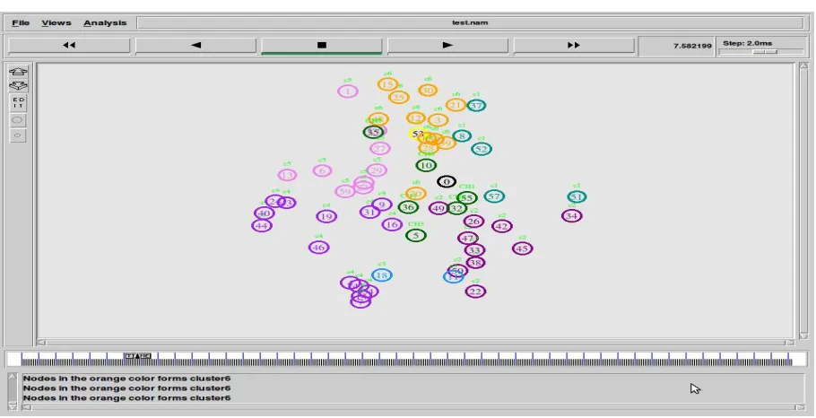
In this section figure 6 shows the scenario of Nam output showing Network Environment before Hexagonal senor Deployment, fig 7 shows scenario of output showing Hexagonal Based Sensor Deployment, fig 8 shows the scenario of cluster head selection and dark green is the cluster head, fig 9 shows scenario of cluster formation by orange color node, fig 10 shows scenario of cluster head selection at different region. fig 11 shows scenario of intra cluster communication, figure 12 shows scenario of data transmission from cluster member to Base station as Source node send data to base station through cluster head and cluster coordinator. Figure13 shows scenario of inter cluster communication; figure 14 shows scenario of Data communication from cluster member to base station.
3. Simulation Results
In this paper, an analysis is done for EFLKMS through some parameters such as total residual energy, throughput, control overhead and storage overhead and the results are compared with EECBKM. Scenario is kept same for both protocols with same topology and energy. EECBKM and EFLKMS protocols are compared for the scenarios of varying number of nodes. Totally 3 simulation runs are made by varying number of nodes as 60,70 and 80.
Fig 6: Scenario of Network Environment before Hexagonal sensor Deployment
ISSN(Online): 2319-8753 ISSN (Print): 2347-6710
International Journal of Innovative Research in Science,
Engineering and Technology
(An ISO 3297: 2007 Certified Organization)
Website: www.ijirset.com
Vol. 6, Issue 8, August 2017
Figure 8: Scenario of Cluster Head Selection
ISSN(Online): 2319-8753 ISSN (Print): 2347-6710
International Journal of Innovative Research in Science,
Engineering and Technology
(An ISO 3297: 2007 Certified Organization)
Website: www.ijirset.com
Vol. 6, Issue 8, August 2017
Fig 10: Scenario of cluster head selection at different region
ISSN(Online): 2319-8753 ISSN (Print): 2347-6710
International Journal of Innovative Research in Science,
Engineering and Technology
(An ISO 3297: 2007 Certified Organization)
Website: www.ijirset.com
Vol. 6, Issue 8, August 2017
Fig 12: Scenario of cluster member to base station
ISSN(Online): 2319-8753 ISSN (Print): 2347-6710
International Journal of Innovative Research in Science,
Engineering and Technology
(An ISO 3297: 2007 Certified Organization)
Website: www.ijirset.com
Vol. 6, Issue 8, August 2017
Fig 14: Scenario of data communication from cluster member to base station
Parameters such as total residual energy, throughput, control overhead and storage overhead are computed and plotted as Xgraph. In figure 14, 15, 16 and 17, the performances of EECBKM and EFLKMS are compared based on the storage overhead, control overhead, actual residual energy and throughput.
Fig 15: : Number of nodes Vs Storage overhead
ISSN(Online): 2319-8753 ISSN (Print): 2347-6710
International Journal of Innovative Research in Science,
Engineering and Technology
(An ISO 3297: 2007 Certified Organization)
Website: www.ijirset.com
Vol. 6, Issue 8, August 2017
Fig 16: number of nodes Vs control overhead
Figure 16: shows the simulation result of number of nodes Vs control overhead. EFLKMS provides decreased control overhead when compared to EECBKM. When the number of nodes increased the control overhead is increased. The EFLKMS provides decreased control overhead compared to EECBKM.
Fig 17: number of nodes Vs Total residual energy
ISSN(Online): 2319-8753 ISSN (Print): 2347-6710
International Journal of Innovative Research in Science,
Engineering and Technology
(An ISO 3297: 2007 Certified Organization)
Website: www.ijirset.com
Vol. 6, Issue 8, August 2017
Fig 18: number of nodes Vs throughput
Figure 18 shows the simulation result of number of nodes Vs throughput. EELKMS provides increased throughput when compared to EECBKM. When the number of nodes increased the throughput is increased. The EFLKMS provides increased throughput compared to EECBKM.
VII. PERFORMANCE EVALUATION
1. Average Residual Energy: It is the average remaining energy available for all the nodes in the network Residual Energy =sum of remaining energy of every node / total nodes
2. Throughput: Throughput is the amount of data successfully received at the sink Throughput (bits/s) = Received data / Duration of data transmission
3. Control overhead: It is the amount of control packets involved in routing process. Control overhead = Number of control packets
4. Storage Overhead: It refers to the number of bytes of stored for key computation.
VIII. CONCLUSION
In this paper, based on the Exclusion Basis System (EBS), an efficient and distributed key management protocol termed as Four Layer Key Management Scheme (EFLKMS) for Hierarchical WSNs is proposed. The proposed mathematical model is supported by the security analysis. The scheme is highly secure and energy efficient. During the data transmission from the cluster members to the BS, the data passes four phases. In the first phase, source node collect data from the environment to communicate to the base station. In the second phase, cluster member to cluster head encryption and decryption by the cluster head key, in the third phase, encryption and decryption between the cluster head and cluster coordinator and in the last phase data encryption and decryption between cluster coordinator and base station based on exclusive base system. Thus this technique allows inter cluster as well as intra cluster communication in a very efficient manner with high security. The proposed scheme can also handle compromised cluster head efficiently. Simulation results reveal that the proposed scheme is energy efficient and supports dynamic key management in dynamic network environment for high level of security.
REFERENCES
[1] M. Becker, A. Gupta, M. Marot, H. Singh, “Improving clustering techniques in wireless sensor networks using thinning process”,. Proceedings of the international conference on Performance Evaluation of Computer and Communication Systems: milestones and future challenges; Springer-Verlag: Berlin, Heidelberg, 2011; PERFORM’10, pp. 203–214.
ISSN(Online): 2319-8753 ISSN (Print): 2347-6710
International Journal of Innovative Research in Science,
Engineering and Technology
(An ISO 3297: 2007 Certified Organization)
Website: www.ijirset.com
Vol. 6, Issue 8, August 2017
[3] M. Eltoweissy, M. H. Heydari, L. Morales, and I. H. Sudborough, “Combinatorial optimization of group key management,” Journal of Network and Systems Management, vol. 12, no. 1, pp. 33–50, 2004.
[4] I. F. Akyildiz, W. Su, Y. Sankarasubramaniam and E. Cayirci, “A Survey on Sensor Networks,” IEEECommunications Magazine, Vol. 40, No. 8, 2002, pp. 102–114.
[5] S. A. Camtepe, and B. Yener, “Key Distribution Mechanisms for Wireless Sensor networks: a Survey,” TR-05-07 Rensselaer Polytechnic Institute Computer Science Department, 2005.
[6] A. Perrig, R. Szewczyk, V. Wen, D. Culler and J. D. Tygar, “SPINS: Security Protocols for Sensor Networks,” Seventh Annual International Conference on Mo-bile Computing and Networking (MobiCom 2001), 2001.
[7] J. P .Walters, Z. Liang, W. Shi and V. Chaudhary, “Wireless Sensor Network Security: A Survey,” LNCS Series: Signals and Communication Technology, 2006.
[8] Q. Huang, J. Cukier, H. Kobayashi, B. Liu and J. Zhang, “Fast Authenticated Key Establishment Protocols for Self-Organizing Sensor Networks,” 2nd ACM international conference on Wireless sensor networks and applications, 2003, pp. 141-150.
[9] B. Dutertre, S. Cheung, and J. Leavy, “Lightweight Key Management in Wireless Sensor Networks by Leveraging Initial Trust,” SRI-SDL-04-02, System Design Laboratory, 2004.
[10] S. Zhu, S. Setia and S. Jajodia, “LEAP: Efficient Security Mechanisms for Large-Scale Distributed Sensor Networks,” 10th ACM conference on Computer and Communications Security, 2003.
[11] J. Deng, R. Han, and S. Mishra, “Security, Privacy, and Fault Tolerance in Wireless Sensor Networks,” Wireless Sensor Networks: A Systems Perspective, Artech House, 2005.
[12] C. Karlof, N. Sastry, and D. Wagner, “Tinysec: A link layer Security Architecture for Wireless Sensor Networks,” Second ACM Conference on Embedded Networked Sensor Systems (SensSys), 2004, pp. 162-175.
[13] D. Malan, M. Welesh, and M. Smith, “A Public Key Infrastructure for Key Distribution in Tiny Os Based on Elliptic Curve Cryptography,” First IEEE International Conference on Sensor and Ad Hoc Communication and networks (SECONO4), 2004.
[14] G. Gaubatz, J. P. Kaps, and B. Sunar, “Public Key Cryptography in Sensor Networks,” First European Workshop on Security in Ad Hoc and Sensor Networks, Heidelberg, Germany, 2004.
[15] D. Liu, P. Ning, and R. Li. Establishing, “Pair-wise Keys in Distributed Sensor Networks,” ACM Trans., Inf. Syst. Secur., Vol. 8, No. 1, 2005, pp. 41–77.
[16] J. Hwang, and Y. Kim, “Revisiting Random Key Predistribution for Sensor Networks,” ACM Workshop on Security of Ad Hoc and Sensor Networks (SASN’04), New York, NY, USA, 2004.
[17] Camtepe, and B. Yener, “Combinatorial Design of Key Distribution Mechanisms for Wireless Sensor Networks,” 9th European Symposium on Research Computer Security, 2004.
[18] . Bohge, and W. Trappe, “An Authentication Framework for Hierarchical Ad hoc Sensor Networks,” ACM workshop on Wireless Security, San Diego, CA, USA, 2003.
[19] J. Deng, R. Han, and S. Mishra, “Enhancing Base Station security in Wireless Sensor Networks”, CUCS University of Colorado, 2003. [20] S. Slijepcevic, M. Potkonjal, V. Tsiatsis, S. Zimbeck, and M. Srivastava, “On Communication Security in Wireless Ad-hoc Sensor Network,”
Eleventh IEEE International Workshops on Enabling Technologies: Infrastructure for Collaborative Enterprises (WETICE’02), CMU, PA, 2002.
[21] S. Rafaeli, and D. Hutchison, “A Survey of Key Management for Secure Group Communication,” ACM Comput.Surv, Vol. 35, No. 3, 2003, pp. 309- 329.
[22] H. Zhu, F. Bao, R. H. Deng, and K. Kim, “Computing of Trust in Wireless Networks,” 60th IEEE Vehicular Technology Conference, Los Angeles, California, USA, 2004.
[23] J. Deng, R. Han, and S. Mishra, “INSENS: Intrusion- Tolerant Routing in Wireless Sensor Networks,” CUCS-939-02, Department of Computer Science, University of Colorado, 2002.
[24] G. Jolly, M.C. Kuscu, P. Kokate, M. Yuonis, "A low-energy management protocol for wireless sensor networks", in: Proceedings of the Eighth IEEE International Symposium on Computers and Communication (ISCC'03), Kemer Antalya, Turkey, June 30-July 3, 2003. [25] D. Xu, J. Huang, J. Dwoskin, M. Chiang, and R. B. Lee, "Re-examining probabilistic versus deterministic key management," in IEEE ISIT,
June 2007, pp. 2586-2590M. [Young, The Technical Writer's Handbook. Mill Valley, CA: University Science, 1989].
[26] T. Lalitha and R. Umarani, "Energy efficient Cluster Based Key Management Technique for Wireless Sensor Network," International Journal of Advances in Engineering & Technology (IJAET), Vol. 3 No. 1, 2012, pp. 186-190.
[27] W. Heinzelman, A. Chandrakasan and H. Balakrishnan, "Energy-efficient communication protocol for WSNs," in Proc. of the 33rd Hawaii International Conference on System Sciences, 2000, Washington.
[28] K. Zhang, C. Wang, and C. Wang, "A secure routing protocol for cluster-based wireless sensor networks using group key management," In Proc. 4th IEEE International conference on Wireless Communications, Networking and Mobile Computing (WiCOM'08), 2008, pp. 1-5. [29] G. Jolly, M.C. Kuscu, P. Kokate, M. Yuonis, "A low-energy management protocol for wireless sensor networks", in: Proceedings of the
Eighth IEEE International Symposium on Computers and Communication (ISCC'03), Kemer Antalya, Turkey, June 30-July 3, 2003. [30] Y. Zhang, Y Shen and S. Lee, "A Cluster-Based Group Key Management Scheme for Wireless Sensor Networks" In: Proc. 12th IEEE
International Asia-Pacific Web Conference, 2010.
[31] A. Shamir, "How to share a secret," Communications of the ACM, vol. 22, no. 11, 1979, pp. 612-613.
[32] A.Chadha, Y.Liu, and S.Das, "Group key distribution via local collaboration in wireless sensor netwroks," in Proc. IEEE Sensor and Ad Hoc communications and Networks, 2005, pp. 46-54.
[33] I.-H. Chuang, W.-T. Su, C.-Y. Wu, J.-P. Hsu, and Y.-H. Kuo, “Two layered dynamic key management in mobile and long-lived clusterbased wireless sensor networks,” in Proc. IEEE WCNC, Mar. 2007, pp. 4145– 4150.
[34] X. Zhang, J. He, and Q. Wei, “EDDK: Energy-efficient distributed deterministic key management for wireless sensor networks,” EURASIPJ. Wireless Commun. Netw., vol. 2011, pp. 1–11, Jan. 2011.
ISSN(Online): 2319-8753 ISSN (Print): 2347-6710
International Journal of Innovative Research in Science,
Engineering and Technology
(An ISO 3297: 2007 Certified Organization)
Website: www.ijirset.com
Vol. 6, Issue 8, August 2017
[36] UshamRobinchandra Singh, Kh. Manglem Singh, Sudipta Roy,” Energy Efficient Key Management Analysis Using AVL Tree in Wireless Sensor Network:” International Journal of Engineering Science Invention Volume 3 Issue 5, pp.57-70, 2015.
[37] I.F. Akyildiz, W. Su, Y. Sankarasubramaniam, and E. Cayirci, “Wireless Sensor Networks: a Survey,” Computer Networks. Vol.38, No.4, pp. 393-422, 2002.
[38] K. Romer, and F. Mattern, “The Design Space of Wireless Sensor Networks,” IEEE Wireless Communications,Vol.11, No.6, pp. 54-61, 2004. [39] A. Modirkhazeni, N. Ithnin, and O. Ibrahim, “Empirical Study on Secure Routing Protocols in Wireless Sensor Networks,”
InternationalJournal of Advancements in Computing Technology, vol. 2, no. 5, pp. 25-41, 2010.
[40] J. Lee, V. Leung, K. Wong, J. Cao, and H. Chan, “Key management issues in wireless sensor networks: current proposals and future developments,” IEEE Wireless Communications, vol. 14, no. 5, pp. 76 –84, 2007.
[41] J. Zhang and V. Varadharajan, “Wireless sensor network key management survey and taxonomy,” Journal of Network andComputer Applications, vol. 33, no. 2, pp. 63-75, 2010.
[42] Zou, Y., &Chakrabarty, K. (2005). A distributed cover-age-and connectivity-centric technique for selecting ac-tive nodes in wireless sensor networks. Computers, IEEE Transactions on, 54(8), 978-991.
[43] Sabbineni, H., &Chakrabarty, K. (2005). Location-aided flooding: an energy-efficient data dissemination protocol for wireless-sensor networks. Computers, IEEE Transac-tions on, 54(1), 36-46.
[44] D. Macedonio, M. Merro, “A semantic analysis of key management protocols for wireless sensor networks", in Science of Computer Programming, pp. 53{78, Elsevier Science, 2014.
[45] X. Du, Y. Xiao, M. Guizani, and H. H. Chen, “An e_ective key management scheme for heterogeneous sensor networks", Ad Hoc Networks, vol. 5, no. 1, pp. 24{34, 2007.
[46] O. K. Sahingoz, “Large scale wireless sensor networks with multi-level dynamic key management scheme", Journal of System Architecture, vol. 59, pp. 801{807, 2013.
[47] M. Turkanovic, B. Brumen and M. H olbl,”A novel user authentication and key agreement scheme for heterogeneous ad hoc wireless sensor networks, based on the internet of things notion", in Ad Hoc Net- works, pp. 96{112, Elsevier Science, 2014.
[48] M. F. Younis, K. Ghumman, M. Eltoweissy, Location-aware combinatorial key management scheme for clustered sensor networks", IEEE Transactions on Parallel and Distributed Systems, vol. 17, no. 8, pp. 865{882, 2006.
[49] A. D. Wood and J. A. Stankovic,(2002) “Denial of service in sensor networks”,Computer, vol. 35(10):54–62, 2002.
[50] S. Datema. A Case Study of Wireless Sensor Network Attacks.Master’s thesis, Delft University of Technology, September 2005.
[51] Adrian Perrig, Robert Szewczyk, J.D. Tygar, Victor Wen, “SPINS: Security Protocols for Sensor Networks”, Department of Electrical Engineering and Computer Sciences, University of California, Berkley, 2002.
[52] DaojingHe,Lincui,HejiaoHang, “Design and verification of Enhanced secure localization scheme in wireless sensor network “IEEE Transaction On parallel and distributed systems vol. 20 no.7 July 2009
[53] Bertalmio, G. Sapiro, V. Caselles, and C. Ballester, “Image inpainting”, in Proc. SIGGRAPH, pp. 417–424, 2000.
[54] A. Criminisi, P. Perez, and K. Toyama, “Region filling and object removal by exemplar-based image inpainting.”, IEEE Transactions on Image Processing, vol. 13, no.9, pp. 1200–1212, 2004.
[55] Marcelo Bertalmio, Luminita Vese, Guillermo Sapiro, Stanley Osher, “Simultaneous Structure and Texture Image Inpainting”, IEEE Transactions On Image Processing, vol. 12, No. 8, 2003.
[56] Yassin M. Y. Hasan and Lina J. Karam, “Morphological Text Extraction from Images”,IEEE Transactions On Image Processing, vol. 9, No. 11, 2000
[57] Eftychios A. Pnevmatikakis, Petros Maragos “An Inpainting System For Automatic Image Structure-Texture Restoration With Text Removal”, IEEE trans. 978-1-4244-1764, 2008
[58] S.Bhuvaneswari, T.S.Subashini, “Automatic Detection and Inpainting of Text Images”, International Journal of Computer Applications (0975 – 8887) Volume 61– No.7, 2013
[59] Aria Pezeshk and Richard L. Tutwiler, “Automatic Feature Extraction and Text Recognition from Scanned Topographic Maps”, IEEE Transactions on geosciences and remote sensing, VOL. 49, NO. 12, 2011
[60] Xiaoqing Liu and Jagath Samarabandu, “Multiscale Edge-Based Text Extraction From Complex Images”, IEEE Trans., 1424403677, 2006 [61] Nobuo Ezaki, Marius Bulacu Lambert , Schomaker , “Text Detection from Natural Scene Images: Towards a System for Visually Impaired
Persons” , Proc. of 17th Int. Conf. on Pattern Recognition (ICPR), IEEE Computer Society, pp. 683-686, vol. II, 2004
[62] Mr. Rajesh H. Davda1, Mr. Noor Mohammed, “ Text Detection, Removal and Region Filling Using Image Inpainting”, International Journal of Futuristic Science Engineering and Technology, vol. 1 Issue 2, ISSN 2320 – 4486, 2013
[63] Uday Modha, Preeti Dave, “ Image Inpainting-Automatic Detection and Removal of Text From Images”, International Journal of Engineering Research and Applications (IJERA), ISSN: 2248-9622 Vol. 2, Issue 2, 2012