Modelling& Simulation of Capacitive Pressure
Sensor Using COMSOL Multiphysics 5.0
Amith.V1, Sushil2, Vyasaraj.T3, Gururaj Hatti4, Vikram Kumar5, Suraj Kumar5, Vandana Kumari5,
Divya S Kamble5
Assistant Professor, East Point College of Engineering &Technology, Bangalore, India1 Assistant Professor, Yenepoya Institute of Technology, Moodabidrae, India2 Assistant Professor Vivekananda College of Engineering &Technology, Puttur,
India
3Assistant Professor, Vishwanathrao Deshpande Rural Institute of Technology, Haliyal,
India
4UG Students, East Point College of Engineering &Technology, Bangalore,
India
5ABSTRACT: This research work provides an overview of developments, challenges with respect to design, modeling, simulation and analysis of MEMS pressure sensors. Recently MEMS capacitive pressure sensors have gained advantages over piezoresistive pressure sensor due to high sensitivity, low power consumption, invariance of temperature effects. As theses sensors application range is increasing, it is essential to review the technological developments and future scope of MEMS capacitive pressure sensor.
This Research Work describes performance analysis of a capacitive pressure sensor working on electro-mechanics interface. Capacitive pressure sensors are advantageous over their counterpart piezoresistive sensors as they consume less power, low sensitivity to temperature, high overpressure capability and high resistance to pressure shocks, improved long term stability, high operating temperature and ease of packaging. In this work, simulation and performance evaluation of electrical and mechanical effects of MEMS based capacitive pressure sensor with square diaphragm using COMSOL Multiphysics is described. This includes diaphragm deflection, sensitivity and linearity analysis, capacitance vs. pressure analysis and thermal considerations. The values of diaphragm displacement and capacitance are plotted under uniform external pressure 25kPa.Two materials are analysed silicon,&graphene and graphene has shown the best and stable result. The simulation results compare the capacitance values with linearized analytical capacitance under same external pressure. The effect of packaging stress on MEMS design process is also emphasized in the paper. It also describes comparison of sensitivity of capacitive pressure sensor with and without packaging stress.
KEYWORDS: Capacitive pressure sensor, COMSOL Multiphysics, diaphragm displacement, Packaging stress, Sensitivity
I. INTRODUCTION
Capacitive pressure sensors are gaining market share over their piezoresistive counterparts since they consume less power, are usually less temperature sensitive and have a lower fundamental noise floor. This model performs an analysis of a hypothetical sensor design as discussed below using the electromechanics interface. The effect of a rather poor choice of packaging solution on the performance of the sensor is also considered. The results emphasize the importance of considering packaging in the MEMS[micro-electro mechanical system] design process.
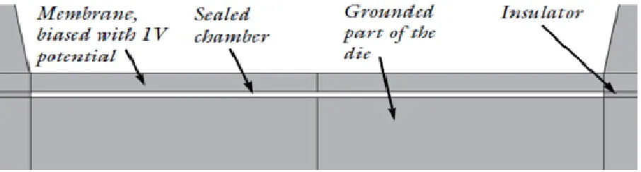
Since the geometry is symmetric, only a single quadrant of the geometry model is taken for analyzing and the symmetry boundary condition can be employed. The functional part of the device consists of a thin membrane biased with 1V potential, a ground plane chamber sealed under high vacuum. The ground part and the membrane are separated by aninsulator. When the pressure outside of the sealed chamber changed, the pressure difference causes the membrane to deflect. Initially the sensor is analyzed in the case where there are no packaging stresses. Then the effect of the packaging stress is considered. The device response at fixed temperature is evaluated with the additional packaging stress. Finally the temperature dependence of the device response at a fixed applied pressure is assessed
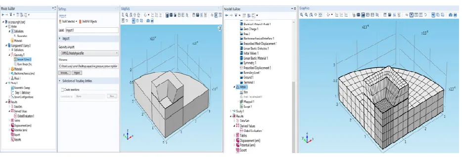
Figure 1: The model geometry. Left: The symmetric device geometry, with one quadrant highlighted in blue, showing the symmetry planes. Right: In COMSOL only the highlighted quadrant is modeled, and the symmetry boundary condition is used on the cross section walls.
A detailed 2D section through the functional part of the device is shown in Figure 2. A thin membrane is held at a fixed potential of 1 V. The membrane is separated from a ground plane chamber sealed under high vacuum. The sides of the chamber are insulating to prevent a connection between the membrane and the ground plane (for simplicity the insulating layer is not modelled explicitly in the COMSOL model—this approximation will have little effect on the results of the study).
II. MATERIALPROPERTIES
GRAPHENE:The simulation model of capacitive pressure sensor is implemented by COMSOL Multiphysics 4.4 software. The model consists of graphene, Steel AISI 4340 and air. The basic geometry of the model is imported from built in COMSOL file. The pressure sensor is part of a graphene die that has been bonded to a metal plate at 70°C. Since the geometry is symmetric, only a single quadrant of the geometry model is taken for analyzing and the symmetry boundary condition can be employed. The operating temperature of the model is 20°C and die bonding temperature is 70°C.
Table:1Material Properties of Graphene
Property Value with Unit
Young’s modulus 1.0 TPa
Poisson’s ratio 0.17
Density 2000 kgm-3
Relative permittivity 2.14
Coefficient of thermal expansion 8*10-6 K-1
SILICON:Silicon is a solid at room temperature, with relatively high melting and boiling points of 1414 and 3265 °C, respectively. Like water, it has a greater density in a liquid state than in a solid state, and so, like water but unlike most substances, it does not contract when it freezes, but expands. With a relatively high thermal conductivity of 149 W•m−1•K−1, silicon conducts heat well. Silicon has become the most popular material to build both high power semiconductors and integrated circuits. The reason is that silicon is the semiconductor that can withstand the highest temperatures and electrical powers without becoming dysfunctional due to avalanche breakdown (a process in which an electron avalanche is created by a chain reaction process whereby heat produces free electrons and holes, which in turn produce more current which produces more heat). In addition, the insulating oxide of silicon is not soluble in water, which gives it an advantage over germanium (an element with similar properties which can also be used in semiconductor devices) in certain type of fabrication techniques. Silicon <100> material is used to design the diaphragms of the pressure sensors. The material properties of silicon have been presented in Table. 2. Silicon <100> has been selected because of its Young‟s modulus.
Table2: Material properties of Silicon
Property Value with Unit
Young’s modulus 170 GPa
Poisson’s ratio 0.06
Density 2330 Kgm-3
Relative permittivity 11.7
III.MODELLING&SIMULATIONPROCESS
Fig 3: Creating the Capacitive Pressure Sensor Model Fig 4:Meshing (mapped)
Fig 5: Diaphragm displacement at 20 kPa external pressure Fig 6: Structure surface of diaphragm with maximum applied pressure & temperature
Table 3:Final Result of Capacitance
IV.CALCULATIONS W = 0.01512 (1 – 2) × (PL4)/(Eh3)
Where,
L is length of diaphragm
PO Capacitance
0.0000 7.3473E-13
5000.0 7.4002E-13
10000 7.4546E-13
15000 7.5107E-13
h is thickness of diaphragm E is Young’s Modulus (GPa)
is Poisson’s ratio
P is applied external pressure and W is maximum diaphragm deflection
C = Ɛ0Ɛ A/d
Where,
0 is permittivity of free space
is relative dielectric constant of material between plates A is effective electrode area
d is separation between plates.
= 0( 1 +12.5 4/2015dD)
C- new capacitance C0-initial capacitance P-Pressure applied
a-half the length of diaphragm d-gap between the electrodes D-flexural density
= ℎ3/12(1− 2)
W =0.01512 (1 – 2)×(PL4)/(Eh3)
=0.01512(1-.172)×203× (0.5×10-3)4 /(1012× (4×10-3)) =2.87×10-7
=0.287µm
D=Eh3/12(1- 2)
=1012(4×10⁻⁶)3/12(1-0.172) =5.492×10⁻⁶ Nm
= 0( 1 +12.5 4/2015dD)
=7.378×10⁻¹³(1+12.5×20000× (0.5×10-3)4/2015×3×10-6×5.492×10-6) =7.378×10⁻¹³(1+0.4708 ) =1.085×10⁻¹²
V. RESULT & DISCUSSION
Table 4: Capacitance comparison of Silicon &Graphene materials
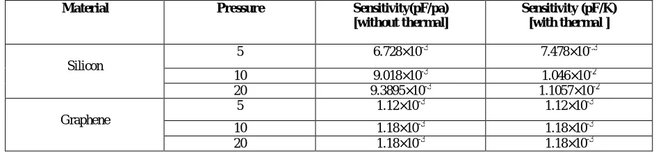
Table 5: Sensitivity comparison of Silicon &Graphene materials
This result shows the response of device in presence of packaging stress. The operating temperature of device is 20℃ and bonding temperature is 70℃. Thermal stresses are introduced due to miss-match in thermal coefficient of expansion of two different materials, silicon and steel base. Thermal stress makes device output temperature dependent due to its dependence on temperature. Graph shows that due to thermal stresses, displacement is more dependent on pressure,The deformation of membrane due to applied pressure causes change in capacitance. The capacitance of device increases non-linearly with applied pressure as shown in graph. It also compares plot of linearized analytic capacitance. It is clearly observed that change in capacitance increases more when packaging stress are taken into consideration as shown in graph. Graph shows the capacitance vs. operating temperature analysis which shows that as temperature increases, capacitance value decreases at uniform external applied pressure. Due to thermal stress, the sensor response has become temperature dependent.
Material Pressure(Kpa) Capacitance(without thermal) Capacitance(with thermal)
Silicon
0 7.3785e-13 7.3604e-13
5 7.7149e-13 7.7343e-13
10 8.1186e-13 8.1941e-13
15 8.6167e-13 8.7805e-13
20 9.2564e-13 9.5718e-13
Graphene
0 15.787e-13 15.790e-13
5 15.843e-13 15.846e-13
10 15.902e-13 15.904e-13
15 15.961e-13 15.964e-13
20 16.023e-13 16.026e-13
Material Pressure Sensitivity(pF/pa) [without thermal]
Sensitivity (pF/K) [with thermal ]
Silicon
5 6.728×10⁻³ 7.478×10-.3
10 9.018×10⁻³ 1.046×10⁻²
20 9.3895×10⁻³ 1.1057×10⁻²
Graphene
5 1.12×10⁻³ 1.12×10⁻³
10 1.18×10⁻³ 1.18×10⁻³
Silicon
Graph 1: Displacement vs. Pressure (with and without thermal stress)
Graphene
Graph 3 : Displacement vs Pressure (with and without thermal stress)
Graph 4 : Capacitance vs Pressure (with and without thermal stress)
The capacitance without package stress is less than the analytic capacitance but the capacitance with package stress is greater than the analytic capacitance graph shows the temperature dependence of the capacitance of the packaged device. The capacitance is decreases linearly with the increasing of the temperature. These analyses clearly demonstrate that the pressure sensitivity can be scaled independently with this graphene material capacitive pressure sensor.
parameter of capacitive pressure sensor. It is defined as the change in the capacitance with respect to change in the pressure applied. In the model the pressure is varied in terms of KPa. Capactiance of the device increases non linearly with applied pressure. A capactive pressure sensor measures a pressure by detecting an electrostatic capacitance change. The deflection of the diaphragm causes the change in capacitance which can be readout as electrical signal using suitable mechanisms like capacitance bridge. The plot shows a linear capacitance change as a function of applied pressure
VI CONCULSION
In this advanced simulation process we have taken four different materials (Silicon.Graphene,Nickel,Silicon Carbide-Membrane material) Graphene has exhibited the highest & best Sensitivity & capacitances.Graphene- When pressure is applied the total Deflection produced is 0.295micron meter& Capacitance:1.6025picofarad.Due to Thermal Effect change in deflection is more.The simulation results was very promising results,it shows high sensitivity,smallsize,free from the effects of temperature,so it may use for various MEMS application.
REFERENCES
[1] Capacitive pressure sensors with stainless steel diaphragm and substrate, Sung-Pil Chang1 and Mark G Allen Georgia Institute of Technology, School of Electrical and Computer Engineering, Atlanta, GA 30332-0250, USA
[2] Simulation Analysis of Capacitive Pressure Sensor for MEMS Using GrapheneRashed Al Amin, SardarMasudRana, Md. ShahidIqbal, Adnan S. R. Rishad, Md. TauhidRayhan, MahbubulHoq, Mohammad Hanif Ali
[3] Performance Evaluation of MEMS Based Capacitive Pressure Sensor for Hearing Aid Application ApoorvaDwivedi, GargiKhanna [4] MEMS Capacitive Pressure Sensors: A Review on Recent Development and Prospective. Eswaran P, Malarvizhi S
[5] A Critical Review of MEMS Capacitive Pressure Sensors Kirankumar B. Balavalad, B. G. Sheeparamatti
[6] Modeling and Simulation of Capacitive Pressure Sensor Using ComsolMultiphysics for Intraoral Applications. Mr.K.Sathesh, Dr.N.J.R.Muniraj, T.DivyaBharathi, S.Priyadarshini, S.Sharmila Research Scholar, Anna University, Chennai, India
[7] Modeling and Simulation of Dual Application Capacitive MEMS Sensor. A. Ravi, R. M. A. Krishna, J. B. Christenl Arizona State University, Tempe, AZ, USA
[8] The Mechanical and Electrical Effects of MEMS Capacitive Pressure Sensor Based 3C-SiC for Extreme Temperature. N. Marsi, B. Y. Majlis, A. A. Hamzah, and F.Mohd-Yasin
[9] Sensitivity Analysis of MEMS Capacitive Pressure Sensor with Different Diaphragm Geometries for High Pressure Applications. Kirankumar B. Balavalad, B. G. Sheeparamatti.
[10] Rahman, M. M. and Chowdhury, S., "Square diaphragm cmut capacitance calculation using a new deflection shape function", Journal of Sensors, Vol. 2011, (2011).
[11] Use of COMSOL Multiphysics to Develop a Shallow Preliminary Conceptual Model for Geothermal Exploration at Pilgrim Hot Springs, Alaska